HAL Id: tel-02301017
https://tel.archives-ouvertes.fr/tel-02301017
Submitted on 30 Sep 2019HAL is a multi-disciplinary open access archive for the deposit and dissemination of sci-entific research documents, whether they are pub-lished or not. The documents may come from teaching and research institutions in France or abroad, or from public or private research centers.
L’archive ouverte pluridisciplinaire HAL, est destinée au dépôt et à la diffusion de documents scientifiques de niveau recherche, publiés ou non, émanant des établissements d’enseignement et de recherche français ou étrangers, des laboratoires publics ou privés.
Enabling traffic engineering over segment routing
Rabah Guedrez
To cite this version:
Rabah Guedrez. Enabling traffic engineering over segment routing. Computer science. Ecole nationale supérieure Mines-Télécom Atlantique, 2018. English. �NNT : 2018IMTA0116�. �tel-02301017�
T
HESE DE DOCTORAT DE
L
’É
COLEN
ATIONALES
UPERIEUREM
INES-T
ELECOMA
TLANTIQUEB
RETAGNEP
AYS DE LAL
OIRE-
IMT
A
TLANTIQUECOMUE UNIVERSITE BRETAGNE LOIRE ECOLE DOCTORALE N°601
Mathématiques et Sciences et Technologies de l'Information et de la Communication
Unité de recherche : Institut de recherche en informatique et systèmes aléatoires (IRISA) Thèse N° : 2018IMTA0116
Par
Rapporteurs avant soutenance :
Béatrice PAILLASSA Professeure au laboratoire IRIT, ENSEEIHT Jean Louis ROUGIER Professeur à Telecom ParisTech
Composition du Jury :
Président : Stefano SECCI Professeur au CNAM
Examinateurs : Béatrice PAILLASSA Professeure au laboratoire IRIT, ENSEEIHT Jean Louis ROUGIER Professeur à Télécom Guillaume
URVOY-KELLER Professeur à l’Université Nice Sophia Antipolis
Encadrants : Samer LAHOUD Professeur associé à ESIB, Université Saint-Joseph de Beyrouth
Dir. de thèse : Olivier DUGEON Ingénieur de recherche à Orange Labs Co-dir. de thèse : Géraldine TEXIER Maître de conférences à IMT Atlantique
Spécialité : Informatique
Thèse présentée et soutenue à Rennes, France, le 12/12/2018
Rendre possible l’ingénierie de trafic dans les réseaux avec routage par segment
Enabling Traffic Engineering Over Segment Routing
This thesis was conducted in collaboration with Orange Labs and IMT Atlantique.
This thesis is dedicated to My beloved parents My wife Sara and my son Adam
Acknowledgements
My deepest and infinite gratitude goes to the Almighty. Without his guidance and support in times of doubt, I’m certain that I would never be able to achieve my goals.
I would like to express my sincere gratitude to my advisors: Dr. Olivier DUGEON, Prof. G´eraldine Texier and Prof. Samer LAHOUD, you have been excellent mentors for me. I would like to thank you for encouraging my research and for allowing me to grow as a research scientist. Your advice on both research as well as on my career have been priceless. I would also like to thank my jury members, Prof. Stefano SECCI, Prof. B´eatrice PAILLASSA, Prof. Jean Louis ROUGIER and Prof. Guillaume URVOY-KELLER for accepting to review my work. I also want to thank you for letting my defense be an enjoyable moment, and for your brilliant comments and suggestions, thanks to you.
My sincere thanks also go to my team at Orange Labs for the wonderful years that I passed among them. In particular, I am grateful to Jean-Marc COROLLEUR who provided me an opportunity to join his team.
My heartful thanks go to all my friends that were always there to support me: Younes, Yazid, Imed, and Raouf.
This moment represents the biggest achievement of my life yet. So, I would like to thank the people who shaped me to the person that I am now. My family. My deepest gratitude and love to my wife Sara, my sisters Wahiba, Soulef, Wissem and my brother Nacer Eddine, I would never be able to thank enough my beloved parents who sacrificed everything to help me get to where I am now. Thank you for giving me the courage and motivation to push forward. Thank you for making me look back and be proud of where i came from. You have always been my North Star when I feel lost.
Resum´
e
L’internet est devenu une partie int´egrante dans la vie des personnes et des entreprises. Cette d´emocratisation de la connexion a permis une incroyable effervescence de nou-veaux services et applications. Les entreprises en profitent pour s’´etendre et acc´eder `a de nouveaux march´es. Actuellement le trafic internet comporte des flux originaires d’un tr`es grand nombre d’applications telles que les appels VOIP, flux vid´eo, jeux interactifs, trading `a haute fr´equence, transactions bancaires, etc. chacune avec des contraints r´eseaux particuli`ere en terme de d´elai, de perte ou de bande passante. Cela a donn´e naissance `a deux types de r´eseaux le r´eseau Internet public et les r´eseaux ´etendus priv´ees : (i) Internet, le r´eseau public mondial o`u IP est la technologie de r´eseau pr´edominante pour le transport de trafic. Bien qu’avec le temps la qualit´e s’est am´elior´ee et le d´ebit a beaucoup augment´e, les applications n’ont pas de garantie ni de contrˆole sur la qualit´e de service (Quality of Service - Qos) qu’elles re¸coivent. (ii) Les r´eseaux ´etendus ou WAN (Wide Area Network) permettent de relier des sites distants `a travers des connexions point `a point d´edi´ees. Au cours des deux derni`eres d´ecennies, la commutation multiprotocole par ´etiquette (MPLS) est devenue la tech-nologie plus r´epandue pour les r´eseaux WAN d’entreprise. Grˆace `a sa capacit´e `a prendre en charge les exigences de qualit´e de service et `a attribuer diff´erentes classes de service (CoS) selon les besoins des applications.
Les op´erateurs tels qu’Orange font face `a des d´efis ´economiques et technologiques consid´erables caus´es par la croissance exponentielle du trafic g´en´er´e par leurs clients ainsi que par la baisse des prix caus´ee par un march´e de plus en plus comp´etitif. En effet, les clients op´erant dans des secteurs sensibles tels que le multim´edia, la finance ou la sant´e comptent sur la fiabilit´e des connexions WAN d´edi´ees pour connecter leurs sites distants et fournir leurs services (par exemple la voix sur IP, la vid´eo `a la demande). Les applications des clients sont de plus en plus sensibles aux d´egradations r´eseau qui peuvent se produire suite `a des pannes, la congestion, ou des probl`emes de routage. Ce qui se traduit par des contrats de niveau de service (Service Level Agreement - SLA) tr`es strict. Afin de g´en´erer des profits, les op´erateurs doivent revoir leur mod`ele ´economique et r´eduire les coˆuts d’investissements et d’op´erations. Cela commence par une simplification du fonctionnement et de la gestion de leurs r´eseaux (complexes) en s’appuyant sur des plans de contrˆole simples et agiles tels que le routage par segment et l’automatisation `a l’aide de briques logicielles.
Pour ces raisons, le groupe de travail SPRING de l’Internet Engineering Task Force (IETF), l’organisme de standardisation des protocoles de l’Internet, a propos´e
l’architecture de routage par segments (Segment Routing - SR). Son objectif principal est de d´evelopper une architecture avec un plan de contrˆole simple, l´eger et facile `a g´erer. Cette architecture peut ˆetre instanci´ee sur deux plans de transfert existants : MPLS et IPv6. Le composant principal de cette architecture est le concept de routage par la source, dans lequel un paquet transporte (dans son en-tˆete) les indications du chemin qu’il doit suivre pour atteindre sa destination. Cette architecture a suscit´e beaucoup d’enthousiasme chez les op´erateurs tels qu’Orange, ce qui se traduit par leur forte implication dans le processus de standardisation. Dans le cadre de cette th`ese effectu´ee au sein d’Orange, nous nous sommes plus particuli`erement int´eress´es `a l’instanciation de l’architecture Segment Routing sur le plan de transfert MPLS (SR-MPLS).
L’un des principaux concepts de l’architecture Segment Routing est la notion de segments, ils repr´esentent les diff´erents composants du r´eseau : physiques (nœud, lien, etc.) ou logiques (service/application). Un identificateur appel´e identificateur de segment ou SID est attribu´e `a chaque segment. Le type et le format du SID d´ependent du plan de donn´ees sous-jacent (une ´etiquette MPLS ou une adresse IPv6). L’empilement d’une liste de segments dans l’en-tˆete du paquet permet l’expression de chemins topologiques. Dans SR-MPLS, un chemin est encod´e sous la forme d’une pile d’´etiquettes MPLS, et qui par la suite est ins´er´ee dans l’en-tˆete du paquet. Un SID est alors repr´esent´e par une ´etiquette de 20 bits et est trait´e en utilisant les trois op´erations habituelle de MPLS : POP pour empiler une nouvelle ´etiquette, PUSH pour d´epiler l’´etiquette courante et SWAP pour en changer la valeur.
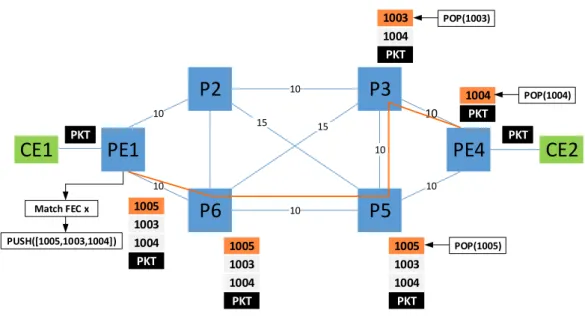
P2 P6 P5 P3 PE4 PE1 CE1 CE2 10 10 10 10 10 10 10 15 15 PKT 1005 PKT PKT Match FEC x PUSH([1005,1003,1004]) 1004 1003 PKT 1005 1004 1003 PKT 1005 1004 1003 PKT 1004 1003 PKT 1004 POP(1005) POP(1003) POP(1004)
Un des avantages de l’instanciation de l’architecture Segment Routing sur le plan de transfert MPLS (SR-MPLS) est qu’elle n´ecessite moins de protocoles de contrˆole que l’architecture MPLS classique. En effet, le d´eveloppement incr´emental de MPLS et l’apparition de nouvelles applications ont conduit aux ajouts successifs de fonc-tionnalit´es et de protocoles, ayant parfois les mˆemes objectifs. Le r´esultat est une architecture complexe, non optimis´ee et tr`es coˆuteuse en ressources. Un exemple con-cret de cette complexit´e peut ˆetre per¸cu lors de l’´etablissement d’un tunnel de r´eseau priv´e virtuel (VPN) pour relier un site client `a un data center `a travers le WAN avec une garantie de bande passante. Ceci n´ecessite la collaboration des protocoles de routage avec un protocole de signalisation et de r´eservation de ressource tel que Resource Reservation Protocol - Traffic Engineering (RSVP-TE). Dans l’architecture SR-MPLS, aucun pr´e-´etablissement de tunnels n’est n´ecessaire, car les paquets suiv-ent le chemin qu’ils transportsuiv-ent dans leur suiv-entˆete. Ainsi, les ´etats des tunnels ne sont maintenus qu’en bordure du r´eseau. Par cons´equent, le nombre d’´etats maintenus dans le r´eseau est consid´erablement r´eduit. Le revers de la m´edaille r´eside dans le fait que l’´elimination de la signalisation perturbe le processus de r´eservation de la bande passante, qui est un composant essentiel pour faire de l’ing´enierie de trafic dans un r´eseau MPLS classique. Pour rem´edier `a ¸ca, une nouvelle approche a ´et´e adopt´ee pour permettre la mise en œuvre de l’ing´enierie de trafic avec du Segment Routing. Cette nouvelle approche s’int`egre bien dans l’´evolution actuelle vers la ”softwariza-tion” des r´eseaux. Dans l’architecture de Software Defined Networking (SDN), un contrˆoleur logiciel pilote un plan de contrˆole SR-MPLS et assure en mˆeme temps la gestion ainsi que la r´eservation des ressources r´eseau, alors que le plan de contrˆole as-sure le transfert des paquets tout en respectant les chemins calcul´es par le contrˆoleur logiciel.
Dans cette th`ese, nous avons identifi´e et propos´e des solutions aux probl`emes pour faire de l’ing´enierie de trafic dans les r´eseaux SR-MPLS (SR-TE). Ce travail est divis´e en deux parties principales : (i) l’identification des d´efis techniques et la r´esolution du probl`eme li´e au cas d’utilisation de l’ing´enierie de trafic. (ii) d´efinition des exigences architecturales et construction d’une preuve de concept fonctionnelle.
0.1
Algorithme native d’encodage de chemins SR
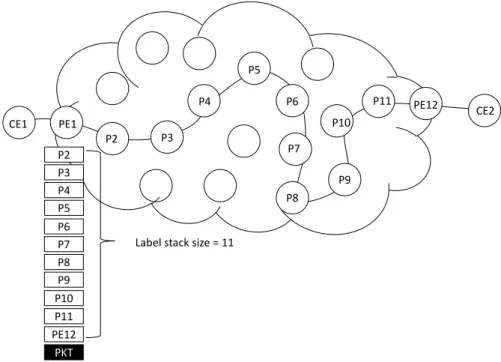
Un chemin SR est encod´e comme une pile d’´etiquettes que le routeur d’entr´ee ins´er´e (PUSH) sur l’en-tˆete du paquet, comme le montre la figure 1. 1. En fait, ins´erer plus d’une ´etiquette a ´et´e support´e depuis la premi`ere version de MPLS [1] pour des
cas d’utilisation comme : hi´erarchisation [2], r´eseau priv´e virtuel de couche 3 [3], etc. Comme on peut remarquer, ces cas d’utilisation n´ecessitent une pile d’´etiquettes relativement petite (deux a trois ´etiquettes.). Par exemple, un sc´enario de L3VPN ne n´ecessite que deux ´etiquettes simultan´ement : l’´etiquette du tunnel et celle du VPN. Cependant, un chemin SR, en fonction de la taille du r´eseau, peut-ˆetre compos´e de plusieurs dizaines segment (SID) ce qui produit une grande pile d’´etiquettes. Par cons´equent, les routeurs doivent pouvoir ins´erer un plus grand nombre d’´etiquettes afin de profiter pleinement du potentiel du SR.
Topologies Nombre de Noeuds Nombr de liens Nombre de demades
Geant 22 36 431
Albilene 12 18 131
Brain 161 166 9045
Germany50 50 80 1270
Nobel-germany 17 26 248
Table 1: caract´eristiques des topologies utilis´ees dans les simulations.
L’encodage des chemins Segment Routing sous la forme d’une pile d’´etiquettes MPLS engendre une surcharge que les ´equipements actuels ne peuvent pas sup-porter. En effet, les ´equipementiers n’ont pas anticip´e l’insertion d’un grand nombre d’´etiquettes MPLS dans les en-tˆetes des paquets. Chaque routeur est con¸cu pour sup-porter une profondeur maximale de pile d’´etiquettes MPLS appel´e MSD (Maximum Stack Depth). Le MSD est une limitation mat´erielle des ´equipements, qui repr´esente le nombre maximum d’´etiquettes qu’un nœud d’entr´ee peut ins´erer sur l’en-tˆete d’un paquet [4]. Actuellement, le MSD varie de 3 `a 5 selon l’´equipementier. Le MSD a un impact fort sur la capacit´e d’un r´eseau SR-MPLS d’exprimer ses chemins. Un chemin est inutilisable en Segment Routing s’il ne peut pas ˆetre exprim´e par un nombre de label suffisamment petit pour que la profondeur de pile d’´etiquettes soit inf´erieure ou ´egale au MSD du routeur charg´e d’ins´erer la pile d’´etiquette sur l’en-tˆete du paquet. Une valeur de MSD petite (comme celle des routeurs actuels) ne permet d’employer qu’un sous-ensemble des chemins du r´eseau SR-MPLS, ce qui concentre le trafic et peut engendrer des pertes et entraˆıner de la congestion.
Les ´equipementiers utilisent des circuits int´egr´es sp´ecifiques aux applications (ASIC) pour acc´el´erer les fonctions de traitement et de transfert des paquets afin d’atteindre des vitesses de transfert importantes. Dans les ´equipements assurant le transfert des paquets MPLS, la limitation MSD provient de l’impl´ementation de l’op´eration PUSH dans les ASICs [5]. Cette limitation doit ˆetre prise en compte dans le processus de
calcul du chemin, car elle peut rendre inutilisables les longs chemins qui sont exprim´es avec une pile d’´etiquettes sup´erieure `a la MSD. Par cons´equent, les flux de trafic sont forc´es sur des chemins relativement courts, ce qui entraˆıne une r´epartition inefficace du trafic ou une congestion aggrav´ee du r´eseau. D’o`u la n´ecessit´e de d´evelopper des algorithmes efficaces pour l’encodage des chemins SR.
Nous avons identifi´e le probl`eme d’encodage des chemins Segment Routing comme un verrou technologique qui doit ˆetre surmont´e pour faire de l’ing´enierie de trafic dans des r´eseaux Segment Routing. Nous avons d´evelopp´e des algorithmes qui permettent de calculer une pile d’´etiquettes minimale pour l’expression de chemins SR. Les algo-rithmes propos´es fonctionnent nativement dans l’architecture de routage par segment. Ils calculent le nombre minimum d’´etiquettes pour exprimer un chemin SR.
Pour ´evaluer la performance de nos solutions, nous avons en premier lieu opt´e pour des simulations proches de sc´enario de production. Pour cela, nous avons s´electionn´e un ensemble de topologies r´eelles [6] avec leurs matrices de trafic, comme on peut voir dans le tableau 1. Nous avons commenc´e par formuler le probl`eme de r´epartition de la matrice des demandes sur la topologie sous-jacente sous la forme d’un programme lin´eaire. Par la suite, nous avons r´esolu ce programme lin´eaire qui a permis de calculer le chemin optimal pour chaque demande. L’ensemble des chemins g´en´er´e par le pro-gramme lin´eaire est ensuite utilis´e pour ´evaluer la performance des deux algorithmes d’encodage. Les r´esultats de simulation montrent une augmentation consid´erable du nombre de chemins qui sont exprim´es avec une profondeur de pile inf´erieure au MSD. Par la suite, nous avons d´emontr´e l’efficacit´e de nos algorithmes avec une impl´ementation dans le contrˆoleur SDN OpenDayLight pilotant une topologie com-pos´ee d’une douzaine de routeurs de production et notre impl´ementation Open Source d’un routeur SR-MPLS.
Ces algorithmes permettent de r´eduire la taille de la pile d’´etiquettes n´ecessaire pour encoder un chemin SR. Bien que les r´esultats soient satisfaisants, ils ne perme-ttent pas d’exprimer la totalit´e des chemins du r´eseau, le MSD restant trop limitant. Pour cela, nous avons propos´e une m´ethode de fragmentation de chemins afin de r´esoudre la limitation MSD (le but est de pouvoir se rapprocher de 100% des chemins exprim´es). Nous avons ainsi propos´e un nouveau type de segment cible appel´e Tar-get SID (TSID) . Ce type de segment permet de cr´eer des raccourcis dans le r´eseau physique pour outrepasser MSD.
0.2
Nouveau type de Segment: Target-SID
Les algorithmes d’encodage natifs que nous avons propos´es permettent de r´eduire consid´erablement l’impact du MSD. Cependant, l’impact de cette limitation persiste pour de tr`es longs chemins, qui ne peuvent ˆetre exprim´es avec une profondeur de pile inf´erieure au MSD mˆeme avec l’optimisant l’encodage. Ces chemins peuvent ˆetre des chemins de supervision ou des chemins dans des topologies de grand diam`etre. Nous avons donc propos´e une nouvelle m´ethode d’encodage des chemins Segment Routing, cette m´ethode de base sur un nouveau type de segment appel´e le Targeted SID (TSID). L’id´ee est de remplacer plusieurs ´etiquettes dans la pile initiale par une seule ´etiquette TSID. C’est dans ce but qu’un chemin est fragment´e en plusieurs sous-chemins. Ces sous-chemins pourront potentiellement ˆetre remplac´es par des TSIDs pendant la phase d’encodage. De plus, les TSID peuvent ˆetre partag´es entre plusieurs chemins pour r´eduire le nombre de TSID cr´e´es dans le r´eseau. L’utilisation des TSID permet de r´eduire la taille de la pile d’´etiquettes pour exprimer un chemin Segment Routing dans la limite du MSD et est encore plus efficace lorsqu’elle est asssoci´ee aux algorithmes d’encodage propos´es pr´ec´edemment. Cependant, les TSID doivent ˆetre install´es au pr´ealable dans le r´eseau avant que le trafic ne soit achemin´e sur le chemin SR. Quand un paquet atteint un nœud sp´ecifique sur son chemin, l’´etiquette TSID en haut de la pile sera remplac´ee par la s´equence d’´etiquettes correspondant `a la portion du chemin qu’il a remplac´e . Nous avons valid´e l’efficacit´e de cette m´ethode sur les topologies pr´esent´ees dans le tableau 1. L’encodage avec des TSID a permis de limiter l’impact du MSD y compris sur les chemins longs.
Certes, la m´ethode du fractionnement des chemins grˆace aux TSIDs permet de r´esoudre le probl`eme du MSD. Cependant, elle n´ecessite de cr´eer et de maintenir de nouveaux ´etats dans les r´eseaux. Un grand nombre de chemins Segment Routing peut g´en´erer un nombre tr`es important de TSIDs. Pour rem´edier `a ce probl`eme, nous avons d´evelopp´e un algorithme en ligne d’optimisation de nombre TSID. Dans cet algorithme, nous encourageons par le biais d’une fonction d’incitation `a r´eutiliser les TSID existants pour satisfaire chaque nouvelle demande d’encodage. Pour ´evaluer les performances de cette solution, nous avons formul´e le probl`eme d’installation d’un nombre minimale de TSID sous la forme d’un programme lin´eaire. Les r´esultats obtenus par l’algorithme en ligne sur les majorit´es des topologies sont proches des r´esultats optimaux obtenus par le programme lin´eaire.
0.3
Conclusion et Perspectives
Notre travail s’inscrit dans le contexte de l’instanciation MPLS de l’architecture de Segment Routing. Cette th`ese a propos´e des solutions pour faire de l’ing´enierie de trafic dans un r´eseau Segment Routing, et ainsi permettre aux op´erateurs de profiter de l’architecture de SR. Nos contributions ont apport´e des solutions algorithmiques pour r´esoudre le probl`eme de la limitation MSD des ´equipements r´eseau. Il est essen-tiel de surmonter cette limitation pour rendre possible une large adoption de Segment Routing par les op´erateurs. Afin de d´emontrer l’efficacit´e des algorithmes propos´es, nous les avons mis en œuvre dans une architecture SDN pour faire l’ing´enierie de trafic dans un r´eseau SR-MPLS. Nos algorithmes d’encodage, ont ´et´e impl´ement´es dans le contrˆoleur SDN OpenDayLight.
Si nos solutions permettent d’utiliser Segment Routing dans les r´eseaux actuels, elles offrent ´egalement des perspectives int´eressantes pour des cas d’utilisation future tels que le chaˆınage de fonctions r´eseau virtualit´es ou la protection contre les pannes. Nous travaillons actuellement sur l’adaptation de nos algorithmes d’encodages pour les appliquer aux chemins de protection calcul´es sur le graphe de topologie post-convergence. Les algorithmes doivent ´eviter le probl`eme de boucle qui peut survenir `a cause d’un mauvais encodage de la pile d’´etiquette ou d’une erreur de calcul sur le chemin poste convergence. Ce travail est guid´e par le standard TI-LFA (Topology-ind´ependant Loop Free Alternate) [¸cois-spring-segment-routing-ti-lfa-02].
Dans un second temps, nous envisageons l’utilisation de Segment Routing dans le cadre de la virtualisation des fonctions r´eseau afin de permettre l’encodage des chemins de chaˆıne de service (NFV Service Chaining). En effet, il est n´ecessaire de pouvoir imposer `a un flux de trafic de passer une suite ordonn´ee de plusieurs fonctions r´eseau virtualis´ees implant´ees dans des nœuds du r´eseau. Dans SR-MPLS, chaque fonction r´eseau est associ´ee `a une ´etiquette MPLS ce qui augmente la taille de la pile pour exprimer le chemin de service. De plus, une fonction r´eseau peut modifier la classe de service du flux qui la traverse. Ces caract´eristiques des chemins de chaˆıne de service doivent donc ˆetre prises en compte dans la conception d’un nouvel algorithme d’encodage.
Contents
0.1 Algorithme native d’encodage de chemins SR . . . 11
0.2 Nouveau type de Segment: Target-SID . . . 14
0.3 Conclusion et Perspectives . . . 15
1 Introduction 1 2 Segment Routing 4 2.1 Introduction . . . 4
2.2 Source Routing . . . 6
2.2.1 Source Routing with IPv4 . . . 8
2.2.2 Source Routing with IPv6 . . . 8
2.2.3 Source Routing with MPLS . . . 9
2.3 Segment Routing Generic Concepts and Terminology . . . 9
2.3.1 Segments and Segment Identifiers . . . 11
2.3.1.1 Segment Routing Global Block SRGB . . . 11
2.3.1.2 Segments Global And Local Scope . . . 12
2.3.1.3 Active Segment . . . 12
2.3.1.4 Segment types . . . 13
2.3.1.5 Segment Routing Paths . . . 14
2.3.2 SPRING Node Configuration . . . 16
2.4 Segment Routing over the MPLS Data Plane . . . 18
2.4.1 Segment Routing MPLS Terminology . . . 19
2.4.2 SR-MPLS Global Segment Implementation . . . 19
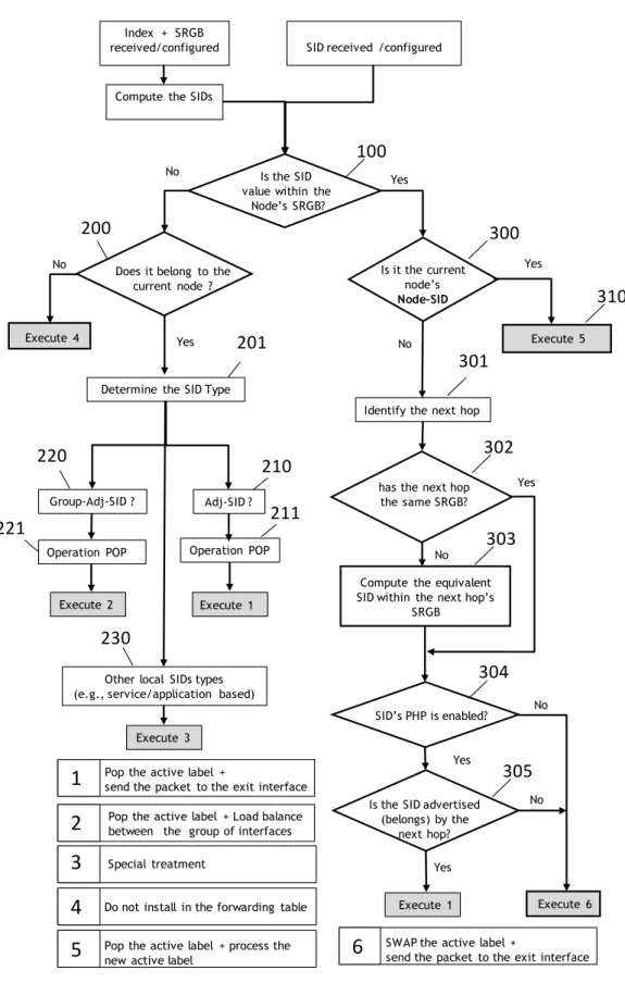
2.4.3 SID Computation . . . 20
2.4.4 Forwarding Operations . . . 22
2.4.5 SR-MPLS Forwarding Entries Installation . . . 24
2.4.6 MPLS Routing Source-routed Path . . . 27
2.4.7 Anycast with SR-MPLS . . . 33
2.5 Use Cases . . . 35
2.5.1 Fast Reroute with Segment Routing . . . 35
2.5.2 IGP-Based MPLS Tunneling . . . 37
2.5.3 Segment Routing Traffic Engineering . . . 39
2.5.4 Monitoring and Measurement . . . 41
2.6 Concluding remarks . . . 43
3 Label Encoding Algorithm for MPLS Segment Routing 44 3.1 Maximum SID Depth Signaling . . . 46
3.2 Related works . . . 46
3.3 Segment Routing Path Encoding . . . 47
3.3.1 Encoding types . . . 48 3.3.2 Encoding algorithms . . . 49 3.3.2.1 Strict Encoding . . . 49 3.3.2.2 SR-LEA Algorithm . . . 51 3.3.2.3 SR-LEA-A . . . 55 3.4 Simulation Results . . . 56
3.5 SR-LEA SDN based Implementation . . . 60
3.5.1 ELEANOR architecture . . . 61
3.5.1.1 Path Computation Module . . . 62
3.5.1.2 Label Stack Optimization Module . . . 62
3.5.2 Testbed Network Topology . . . 63
3.5.3 FRRouting-SR . . . 64
3.6 CONCLUSION . . . 65
4 A New Method For Encoding MPLS Segment Routing TE Paths 67 4.1 Introduction . . . 67
4.2 Related Work . . . 68
4.3 Path Segmentation . . . 68
4.3.1 Targeted SID Architecture . . . 70
4.4 Offline TSID Placement Models . . . 71
4.4.1 Offline Optimization of TSIDs Placement . . . 72
4.4.2 Offline Minimization of PCEP sessions . . . 73
4.4.3 Online Algorithms . . . 74
4.5 Experimental Results . . . 77
4.5.1 OTO for TSIDs minimization . . . 77
4.6 CONCLUSION . . . 82
5 General Conclusion and future work 83 5.1 Future Work . . . 86
Appendices 90
A Segment Routing over IPv6 Data Plane 91 A.0.1 SR-IPv6 Terminology . . . 91 A.0.2 Segment Routing Header . . . 92 A.0.3 SR-IPv6 forwarding operations . . . 94
Conclusion 102
List of Figures
1 Transfert de paquets dans un r´eseau SR-MPLS . . . 10
2.1 Source Routing Example . . . 7
2.2 Reference network topology . . . 12
2.3 Hierarchy of the different segment types . . . 14
2.4 An example of Segment Routing Path . . . 15
2.5 Configuration of Segment Routing on nodes using a Network Manage-ment System (NMS) . . . 16
2.6 Configuration of Segment Routing on nodes using a Mapping Server . 17 2.7 Segment Routing operations . . . 23
2.8 State Machine of SR-MPLS Forwarding Entries Installation . . . 26
2.9 Packet header when using MPLS data plane for Segment Routing . . 28
2.10 Example of Segment Routing path with one Node-SID only: Routers use the same Segment ID to forward the packet following the shortest path up to the Node SID. . . 29
2.11 Example of Segment Routing path where the label stack is composed only of Node-SIDs . . . 30
2.12 Example of Segment Routing path where the label stack is composed of only Adj-SIDs . . . 31
2.13 Example of Segment Routing path where the label stack is composed with node-SIDs (PE1 to P3 and P5 to PE4) and Adj-SIDs (P3 to P5) 32 2.14 Load balancing of flows using Group-Adj-SID . . . 32
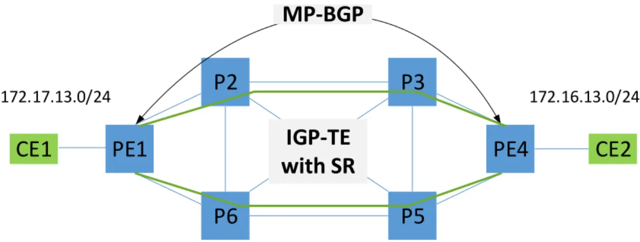
2.15 Local protection of the link between P2-P3 with Segment Routing . . 36 2.16 Standard MPLS VPNs with LDP or RSVP-TE for labels distribution 37 2.17 Segment Routing based MPLS VPN:MP-BGP for VPN labels exchange,
2.18 A Path Computation Element (PCE) is used to compute Segment Routing paths for Traffic Engineering. PCE protocol (PCEP) is used to send the label stack and BGP-LS protocol is used to collect topology
information . . . 41
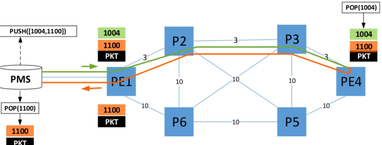
2.19 Network monitoring with Segment Routing. The SR path is composed of the round-trip stack . . . 42
3.1 Reference network topology, all the links costs are 10 except the link P3-P7 its cost is 100. . . 45
3.2 loose or strict path classification. . . 48
3.3 Reference network topology, all the links costs are 10 except the link P3-P7 its cost is 100. . . 49
3.4 The problem that rises when expressing the SR path to connect CE1 and CE2 exclusively using Node-SIDs. . . 50
3.5 The SR path to connect CE1 and CE2 is expressed exclusively using Adj-SIDs by a strict encoding algorithm. . . 51
3.6 SR-LEA flowchart. . . 52
3.7 The SR path to connect CE1 and CE2 is expressed as a label stack computed using the SR-LEA algorithm. . . 54
3.8 The SR path to connect CE1 and CE2 is expressed as a label stack computed using the SR-LEA-A algorithm. . . 56
3.9 Comparison of the average label stack size generated using a strict encoding, SR-LEA and SR-LEA-A algorithms. . . 58
3.10 Paths expressed with a label stack size lower that the MSD (M SD = 5). 58 3.11 Comparison of SR-LEA and SR-LEA-A over a large set of paths. . . 59
3.12 ELEANOR Reference Architecture . . . 61
3.13 ELEANOR software architecture . . . 63
3.14 Testbed Topology . . . 64
3.15 FRRouting-SR: Open source implementation of SR-MPLS . . . 65
4.1 TSID Design Architecture. . . 69
4.2 OTO for TSIDs minimization compared to the worst-case scenario i.e., online TSID installation with no optimization. . . 78
4.3 OTO for TSIDs minimization compared to the Offline LP for TSIDs minimization . . . 78 4.4 Comparison of the number of TSIDs created by the two offline LPs . 79
4.5 Comparison of the number of TSIDs created solely by OTO and SR-LEA encoding algorithm combined with OTO . . . 80 4.6 OTO for PCEP sessions minimization compared to the worst-case
sce-nario of an online TSIDs installation with no PCEP optimization. . . 81 4.7 OTO for PCEP sessions minimization compared to the offline LP for
PCEP sessions minimization . . . 81 4.8 Comparison of the number of PCEP sessions required by the two offline
LPs . . . 82
A.1 Header of IPv6 packet with Segment Routing . . . 93 A.2 illustrates how the SRH can be added to a client IPv6 packet : a) SRH
added at the end of the original IPv6 packet extension header. b) client packet is encapsulated into a new IPv6 packet, the SRH is added into the extension header of the new IPv6 packet . . . 95 A.3 State Machine of IPv6 node forwarding behavior when using Segment
Routing . . . 96 A.4 Example of Segment Routing path when using IPv6 data plane . . . 97
Chapter 1
Introduction
Service Providers are facing extreme challenges to keep pace with the exponential growth of their client’s traffic. Moreover, clients are requesting more strict Quality of Service (QoS) requirements for their sensitive applications such as medical, finan-cial, real-time videos calls and streaming application resulting in tightened Service Level Agreements (SLA). Consequently, service providers need to meet those require-ments while reducing cost. One of the solutions they are adopting is simplifying their complex networks and rely more on software to reduce the operational expense and capital expenditure.
Organizations operating in highly demanding environments such as banking, trad-ing, medical, etc. rely on dedicated Wide Area Network (WAN) connections to con-nect their remote sites. Mainly because of the guaranteed QoS requirements such as bandwidth, protection, delay, etc. that the service providers deliver. For that, service providers invest in building and maintaining specialized WANs to satisfy the increasing demands. The majority of these networks run on the Multiprotocol Label Switching (MPLS). However, over the years and with the increase of use cases the MPLS control plane grow increasingly complex, which required a variety of intercon-nected protocols built by different standardization working groups, thus making it hard to manage, troubleshoot and evolve.
For the reasons mentioned above, the Internet Engineering Task Force (IETF) SPRING working group has proposed the Segment Routing (SR) architecture. Its main objective is to have a simple and easy to manage control plane. It relies on an old networking paradigm known as source routing, where a packet carries in its header the path to reach its destination. This architecture has generated a lot of enthusiasm among service providers such as Orange, due to the simplification that it brings to their IP/MPLS networks. In fact, the instantiation of SR architecture over the MPLS data plane requires less control plane protocols: There is is no need
to pre-establish tunnels and the per-flow states are maintained only at the edges of the network. Therefore, no signaling protocols such as LDP and/or RSVP-TE are re-quired. Consequently, the number of states maintained in the network is considerably reduced. However, the elimination of signaling disrupts the bandwidth reservation process which is an important tool for traffic engineering. The lack of such an impor-tant use case makes the service providers hesiimpor-tant to migrate their networks to SR. In this thesis, we identify and solve the problems that must be overcome to do traffic engineering over SR (SR-TE) in IP/MPLS networks. Our work is divided into two main parts: Identify and address the technical challenges to deliver such use case, define architectural requirements, and build a working proof of concept.
In Chapter 2, we introduce the SR architecture and detail its building blocks. We detail the implementation specifics SR-MPLS. We finish by detailing few use cases where SR can have an important impact.
In Chapter 3, we first focus on defining a reference architecture to achieve traffic engineering over SR. Interestingly, Software Defined Networks (SDN) has the capac-ity to fill the gap of resource reservation and management in the SR architecture. In fact, SR does not rely on signaling. Therefore, the resources availability does not get updated throughout the network, which may lead to overbooking and poor net-work utilization. Consequently, resource reservation and management mechanisms functionalities are developed into an SDN controller who will maintain a central-ized Traffic Engineering Database (TED). Additional functionalities can leverage the TED such as path computation and network optimization, etc. we build the proposed architecture using the OpenDayLight SDN Controller coupled with a testbed com-posed of commercial routers running SR control plane. Secondly, we use the procom-posed architecture to address the Maximum Segment Identifier Depth (MSD) hardware lim-itation. Which limits the number of labels a router can push onto a packet’s header. This prevents the expression of a considerable number of network paths causing a sub-optimal network resources utilization. The MSD may slow down the adoption of SR. To solve this problem, we propose two label encoding algorithms that slacken the impact of the MSD by reducing the size of the label stack to express segment routing paths. Both algorithms work natively without any additions to the SR architecture. We prove the effectiveness of both algorithms through simulation over real network topologies. In addition, we develop into OpenDaylight a label encoding engine that leverages both algorithms.
In Chapter 4, we propose a new method to optimize the encoding of SR paths and therefore reduce the impact of the MSD limitation. In this approach, we define
a new segment type called Targeted Segment Identifier (TSID). It is used in the encoding of SR paths, where a single TSID is used to substitute multiple labels in SR path description. We propose an SDN based architecture to implement the TSID mechanism. Additionally, we propose and compare several optimization algorithms to reduce the overhead introduced by TSID architecture.
Finally, in Chapter 5 we present the general conclusions of this thesis. We empha-size the major contributions of this work, point out the open issues and the interesting future directions.
Chapter 2
Segment Routing
2.1
Introduction
In September 2013, the Internet Engineering Task Force (IETF) started a new Work-ing Group (WG) called ”Source Packet RoutWork-ing in NetworkWork-ing” (SPRING) to stan-dardize the Segment Routing (SR) architecture. One the main goal of this new architecture is to address the complexity of Multi-Protocol Label Switching (MPLS) networks that are currently used by Service Providers to transport data in their core networks.
Over the years, MPLS has gained acceptance as the de facto technology to de-ploy large IP networks. Thanks to the efforts made by the IETF standardization working groups, MPLS control plane has continuously evolved in order to improve the performance, scalability and provide support for new services. The introduced enhancements required the definition of new protocols e.g., Resource Reservation Pro-tocol Traffic Engineering RSVP-TE, the Label Distribution ProPro-tocol (LDP) and the extension of others : Open Shortest Path First (OSPF) [7], Intermediate System to Intermediate System (IS-IS) [8] and the Border Gateway Protocol Link State [9].
Traffic engineering represents an essential task for service providers. It optimizes the use of the network resources (e.g., send traffic through less congested links), makes sure that client Quality of Service (QoS) requirements are met and enforces network resiliency by bypassing link and node failures through fast reroute. An MPLS network with traffic engineering capabilities is referred to as MPLS-TE.
The MPLS-TE control plane consists mainly of the two protocols: RSVP-TE to establish and maintain Label Switched Paths (LSPs), and an IGP protocol to advertise the network resources. Large networks with a large number of MPLS-TE LSPs suffer from scalability issues [10] due to RSVP-TE, which consumes a significant amount of node resources: memory storage to maintain millions of states, processor
cycles to process these huge state tables and to synchronize the control protocols. Indeed, after a node restart, the number of messages exchanged over the links to repopulate the state tables can cause node congestion, which involves packets being dropped and/or retransmitted and increases network convergence time.
As an example, let us consider a network of a WAN network composed of 1,000 edge routers and 60 core routers. In order to establish a full-mesh of MPLS-TE LSPs between the edge routers, each edge router has to establish 999 LSPs. Consequently, the core routers have to manage and maintain a total of 999,000 LSPs, this number may be multiplied in the case of establishing dedicated TE LSPs for each service or QoS class, this phenomenon is known as the N-Squared problem [11]. Therefore, the network performance is severely impacted by the RSVP-TE refresh mechanism, used to maintain up all the instantiated LSPs in the network. Some techniques such as grouping the refresh messages of multiple LSPs in one or increasing the refresh period are used to overcome the RSVP scalability issues [12]. However, these are fixes that do not address the core problem. Also, using a hierarchy of LSPs reduces the number of LSPs to maintain in the core routers. Or, RSVP-TE may be used to only deliver node and link protection [13] while LDP is used to deliver VPN services without bandwidth reservation.
Finally, the complexity of the management and the configuration of traffic en-gineering information on the routers prevents their efficient exploitation. Service Providers have become aware of the problems with MPLS and reached a point where a global simplification of its control plane is necessary.
SR was introduced in order to overcome these issues and to simplify the use of MPLS. SR leverages the source routing paradigm, where the path taken by the packet to reach its destination is encoded in its header. The most important building block of this architecture is the concept of segments [14]. Basically, a segment can repre-sent a topological path (e.g., the shortest path to a node) or service (application). Combining two or more segments allows the expression of any network path. In-stead of using a dedicated protocol, segments are advertised using routing protocols. SR architecture [15] [16] can be instantiated over two data planes: MPLS, without any data plane modification and an IPv6-based solution that requires a hardware upgrade. SR over MPLS data plane (SR-MPLS) simplifies the deployment and con-figuration of services such as fast reroute (link and node protection) and VPNs, by eliminating the need for protocols like LDP and/or RSVP-TE. Equipment vendors have already started delivering the support for SR in their recent software releases. The first interoperability tests have been conducted internally by service providers
or by independent entities such as the European Advanced Networking Test Center (ENTC) [17].
In this chapter, we take a deep dive into the SR architecture. First, We start by introducing source routing in section 2.2. Second, we detail the different building block of SR in section 2.3. Third, we detail the MPLS in in section 2.4 implementation. Finally, we detail several SR use cases in section 2.5.
2.2
Source Routing
The source routing paradigm was first introduced in the early versions of the Inter-net Protocol IPv4 [18]. Since then various Inter-network architectures and protocols have adopted it, such as MPLS [19], IPv6 [20] and wireless networks protocols: Dynamic Source Routing DSR [21] and Source Demand Routing Protocol (SDRP) [22]. Addi-tionally, source routing is a main component of the SR architecture. Understanding source routing is essential for a better grasp of SR. For that purpose, we detail in this section the functioning of source routing and its implementation in different protocols. Source routing enables the source node (ingress) to specify explicitly the path that packets have to follow in order to reach their destination. The Source-Routed Path (SRP) consists of a sequence of nodes and links the packets pass through. The components of the SRP (nodes, links) are carried in every packet header. The SRP can express any topological paths. Consequently, it allows forwarding of traffic on paths that are not the IGP shortest paths. Such characteristic is interesting for multiple use cases such as traffic engineering, path monitoring and troubleshooting. We distinguish two types of Source Routing:
1. Strict Source Routing: in strict source routing, all the intermediate hops (nodes, links, etc.) between the source and the destination are listed in the packet header. In this case, the packet must pass through exclusively the listed hops. Two successive hops in the packet header are adjacent. Intermediates nodes do not have to determine the next hop because the forwarding decision is only based on the information carried in the packet header. In Fig. 2.1, service provider connects two Customer Edge (CE) routers CE1 and CE2, and decides that the traffic sent from CE1 to CE2 follows the path A: P E1 → P 2 → P 3 → P E4. Hence, P E1 receives packets from CE1 then encodes into each packet header the list of all the intermediate hops identifiers. When the packet reaches a given node, this node looks up the reference of the next hop in the list in order to
determine to which hop it must forward the packet. Finally, P E4 removes the hop list before forwarding the packet to CE2.
2. Loose Source Routing: in loose source routing, the packet carries only a subset of the hop identifiers that constitute the full path. The packet goes through all the hops listed in the header but not only i.e., packets may go through hops that are not present in their header. This happens when two successive hops in the packet header are physically separated by one or more intermediate nodes. Going back to our example shown in Fig. 2.1, CE1 sends its traffic to CE2 following path B: P E1 → P 3 → P E4, only P 3 is specified as an intermediate node. In this case, P E1 determines that P 6 is the next hop to reach P 3 by looking up its forwarding table. This is considered as a loose path because P E1 and P 3 are not direct neighbors, consequently packets have to go through P 6, which is not present in the hop list of the source path.
P2
P6
P5
P3
PE4
PE1
CE1
CE2
10 10 10 10 10 10 10 5 10 PKT PE4 P3 P2 PKT PE4 P3 P2 PKT PE4 P3 P2 PKT PE4 P3 P2 PKT PE4 P3 PKT PE4 P3 PKT PKT PKT PE4 P3 PKT PKT PKT PE4 P3Path A: Strict path Path B: Loose path
Figure 2.1: Path A is a strict path where all the intermediate nodes are carried in the packet header. Path B is a loose path because only a subset of the intermediate nodes is carried in the packet header
2.2.1
Source Routing with IPv4
As mentioned above, source Routing was introduced in the early versions of the IPv4 standards [18], it was implemented as an option in the IPv4 header, for which two types were defined: type 131 for Loose Source and Record Route (LSRR) and type 137 for Strict Source and Record Route (SSRR).
IPv4 standard limits the length of the SRP to a maximum of 9 IPv4 addresses because it is transported as an option in the IPv4 packet header, which has a maxi-mum size of 40 Bytes. Each node crossed by the packet gets recorded, which allows the destination to build its own loose or strict route in order to respond via the same path.
IPv4 source routing was originally used by network administrators to perform tasks such as network discovery, measurements and debugging. Due to the discovered vulnerabilities and its exploitation for malicious purposes [23], such as conducting De-nial of Service attacks, spoofing attacks, firewall bypassing and other attacks. Thus, the majority of network administrators have disabled the support of these options in their networks. As a result, the IETF advice now that packets with LSRR and SSRR options should be dropped [24].
2.2.2
Source Routing with IPv6
The source routing behavior from IPv4 was reproduced in IPv6 extension header Type 0 Routing header (RH0), copying almost the same concepts as in IPv4. Contrarily to IPv4, the RH0 is an extension header and its size is limited only by the maximum transmission unit. For this reason, an RH0 can carry longer paths in comparison to IPv4. For example, with a maximum transmission unit of 1500 Bytes, an SRP can be composed of 90 IPv6 addresses, with the possibility to include the same address multiple times. However, big SRPs have made things worse from a security point of view. For example, a Denial Of Service attack can be carried out via traffic amplification on a specific path between two nodes, this attack is more powerful with RH0 than with IPv4 source routing, due to the fact that the number of IP addresses carried in the RH0 is much greater than IPv4 source routing option: the RH0 can carry up to 90 addresses compared to only 9 for IPv4, this gives the attacker the possibility of oscillating up to 44 times between two nodes, which would eventually cause a congestion on that path. As a result, the IETF deprecated the support of RH0 [25].
The deprecation of RH0 was intended to stop its exploitation for malicious pur-poses, but not to prevent totally the use of source routing in IPv6 networks. Indeed, new secure routing headers were defined to deliver source routing for different net-works types. For example, an IPv6 Routing Header for Source Routes with the Routing Protocol for Low-Power and Lossy Networks [26] and the Segment Routing extension header [27] (see Section A).
2.2.3
Source Routing with MPLS
MPLS networks also took advantage of source routing. Using the PUSH operation multiple labels get added to the packet’s header, this is known as label stacking. Each label from the stack identifies a unique LSP. These LSPs are pre-established either by RSVP-TE or by LDP or BGP. Each intermediate node installs a state in its forwarding table for each LSP that goes through it.
Unlike IPv4/IPv6 implementation of source routing where an IP address identifies a unique node. In MPLS, a label is local to the node and it determines the path to a hop (either direct or over an LSP). Additionally, MPLS implementation does not suffer from the same security issues as in IPv4/IPv6, because a service provider drop traffic originated from untrusted sources.
In the next section, we go into more detail on how SR architecture leverages the source routing paradigm and the implementation specifics for each data plane: MPLS and IPv6.
2.3
Segment Routing Generic Concepts and
Ter-minology
As mentioned in the previous section, source routing is used since the early days of internet protocols. Although, it constitutes a core routing mechanism in environments such as ad-hoc wireless networks [21, 22]. It was always implemented as extensions for the IP protocols to solve specific use cases. The classical shortest path stayed the de facto routing forwarding mechanism. The lightweight and the flexibility of source routing in the expression of topological paths led the IETF to create the Source Packet Routing in Networking (SPRING) working group, that works to define and standardize the segment routing architecture that leverages source routing. In this section, we define and detail the main concepts of SR.
In fact, SR is not a new protocol, but rather an architecture that defines a set of requirements to implement source routing over IP networks. The SPRING working
group focuses on the definition and the standardization of SR architecture and its use cases. Additionally, other IETF working groups work on the definition of pro-tocol extensions: Open Shortest Path First (OSPF), IS-IS for IP Internets (ISIS), Inter-Domain Routing (IDR) for BGP, Path Computation Element (PCE), and IPv6 Maintenance (6man).
Service provider core networks are experiencing limitations due to the growing number of services and protocols deployed, which creates a barrier towards achieving its optimal exploitation [10]. Therefore, in order to support the ever-growing number of protocols, services and policies, network nodes are forced to maintain and manage large state tables, which consumes a large amount of the node’s memory and process-ing resources. It also becomes very difficult for network administrators to manage and troubleshoot. All these points were taken into consideration by the SPRING working group when defining the SR architecture. The SR architecture is focused on the simplification of the node’s control plane and the reduction of states maintained in forwarding tables. For instance, in an MPLS network with SR deployed there is no need to pre-establish tunnels using RSVP-TE because the instructions to forward the packets are carried in their headers. This leads to a considerable reduction in the number of states maintained by the intermediate nodes. Finally, the SR architecture does not require additional protocols: it extends those already deployed, such as the Internal Gateway Protocols (IGP) e.g., OSPF [7] and ISIS [8] have been extended to exchange SR information. SR main architectural concepts can be summarized in the following points:
• Avoid as much as possible deploying new protocols dedicated for SR-MPLS,
• Extend already deployed protocols used by the IP/MPLS networks (OSPF, ISIS, BGP-LS),
• Maintain per-flow states only at the network boundaries and reduce the flow states maintained by the intermediate nodes.
SR is a generic architecture that can be instantiated over existing data planes; this reduces its deployment cost and accelerates its mastering by the service provider’s engineers. Depending on the existing hardware, SR deployment requirement varies from a software upgrade to new hardware. Sections 2.4 and appendix A we explain in more detail the deployment challenges of SR-MPLS and SR-IPv6 respectively. In addition, SR can be deployed gradually because the control plane protocol extensions are designed to be backward compatible. This enables SPRING nodes to interoperate with other nodes that are not SR enabled.
2.3.1
Segments and Segment Identifiers
One of the main concepts in SR architecture is the notion of segments. They rep-resent different network components: physical (node, link, etc.) or logical (ser-vice/application). An identifier called Segment Identifier or SID is attributed to each segment. The SID type and format depend on the underlying data plane (an MPLS label or an IPv6 address as explained in Section Sections 2.4 and A). An SID can have a global significance in the domain or local to the node advertising it. Stacking a list of SIDs into the packet header allows the expression of (strict or loose) topological paths. For the rest of the manuscript the terms segment and SID are interchangeable.
In SR, a source route is encoded by the ingress node as a sequence of segments in the packet header. Each individual segment has a corresponding data plane for-warding instruction. The interpretation of the segment list creates an end-to-end path. Intermediate nodes may modify the path by adding or removing one or more segments from the packet header. A segment can represent a node, a link, a Border Gateway Protocol (BGP) peering adjacency, an LSP, or even a service.
SR flexibility in expressing topological or service-based paths makes it very at-tractive for data centers or service provider networks. For example, a segment can be interpreted by an intermediate node as send packet to node N via the IGP shortest
path, send this packet to a Deep Packet Inspection (DPI) virtual machine or forward packet through this node’s interface X. Moreover, the possibility of deploying this new
architecture over existing data planes with no or minor changes favors its wide adop-tion. Currently, two data planes are considered for its instantiation [10]: an MPLS data plane without any changes and IPv6 with a new type of Routing Extension Header.
2.3.1.1 Segment Routing Global Block SRGB
Service providers may consider deploying SR in a gradual manner. For example, one may choose to deploy SR over only a subset of the network nodes (e.g., PEs), or use it to enable specific use cases such as Fast Reroute (FRR). Consequently, SR control plane has to co-exist and interoperate with other control plane protocols on the same node or over the network. For that, mechanisms are needed in order to avoid conflicting or duplicated entries in the forwarding plane. Therefore, each SPRING node reserves an SID block only for SR use: in the case of SR-MPLS a block of labels or a block of IPv6 addresses for SR-IPv6. This block is named the Segment Routing
Global Block (SRGB). Reserving the same SRGB throughout the network is highly
recommended because it simplifies operations and troubleshooting. SR information such as the SRGBs and SIDs are advertised inside a domain using the IGP protocol.
P2
P6
P5
P3
PE4
PE1
CE1
CE2
Node-SID PE1 Adj-SID PE1-P6IGP {Node-SIDs (P2,PE1)}
IGP {Node-SIDs (P3,PE4)}
Figure 2.2: Reference network topology
2.3.1.2 Segments Global And Local Scope
The scope of an SID may be domain wide or local to a particular node. An SID is global (i.e., unique in a SPRING domain) if it takes its value within the SRGB. In addition, a global SID has an associated entry in the forwarding tables of all the SPRING nodes, this is detailed in Section 2.4.2. The SID can also be local to the node advertising it. Consequently, the same SID may be reused and therefore advertised by other nodes. A local SID takes its value outside the SRGB. The local SID is readvertised by all the SPRING nodes but only its owner installs a forwarding entry associated with it. The entry in the forwarding table refers to the next hop, which has been determined based on the IP forwarding table.
2.3.1.3 Active Segment
An active SID is the one that the current node uses to make a forwarding decision. It can be the top label in an MPLS stack or the IPv6 address in the Destination Address (DA) of the IP header. Every SID the encode the SR path becomes at least once active before the packet reaches its destination. A global SID may stay active and span several nodes. For example, the routers IPv6 loopback address in SR-MPLS. A local SID must become active only on the node that advertises it. For example, the SID attached to a specific router interface in SR-MPLS.
2.3.1.4 Segment types
The type of a segment depends on the way it is advertised and the network component that it identifies, as shown in Fig. 2.3. Consequently, the segment advertised in the IGP is named the IGP segment. In IP networks, network components are identified by IP addresses which are advertised as IGP prefixes. In SR the SIDs attached to these IGP prefixes are named IGP Prefix Segments (Prefix-SIDs). For example, an SID can be attached to a unicast IGP prefix (e.g., router loopback or an adjacency) as shown in Fig. 2.2, or an IGP anycast prefix (e.g., DNS, CDN, etc.). With the emergence of new use cases, it is likely that new SID types will be defined in the future. In this manuscript, we focus on the two main SID types: Node-SID and adjacency SID (Adj-SID) as shown in Fig. 2.2. Both segment are sufficient to encode any intradomain SR path. They are defined as follows:
• An Node-SID is a Prefix-SID, it is a unique identifier (global SID) in the SR domain. It is assigned to a specific node. Specifically, it is attached to one of the node’s loopback addresses. Every SPRING node has an entry in its forwarding table for every Node-SID in the SPRING domain. When a node receives a packet with a Node-SID as the active SID, it forwards the packet down the path that results from the IGP path computation algorithm. For example, if the node uses the standard Shortest Path First SPF algorithm, it executes the following forwarding instruction: forward this packet down the shortest-path to
the node that has this SID.
• An Adj-SID is an IGP segment, it is an identifier that has a local significance. It is used to identify an adjacency between two nodes. Only the node advertising it has a forwarding entry corresponding to that SID. When a node receives a packet with an Adj-SID as the active SID in the stack, it executes the following forwarding instruction: send this packet out of a specific interface.
A Prefix-SID is associated with a forwarding instruction derived from the rout-ing table computed by node’s path computation algorithm. In SR, it is possible to assign Prefix-SIDs per path computation algorithms. Consequently, a SPRING node advertises multiple Prefix-SIDs for one IGP prefix (i.e., one per algorithm), the topo-logical path varies depending on the path computation algorithm used. Currently, two algorithms are defined: type 0 which is a standard SPF based on the link metrics, type 1 which is the a strict SPF, it is identical to a standard SPF, but it requires that the nodes on the path respect the computed path even if it contradict local
Segment
Other Segments
IGP Segment
IGP-Adjacency Segment
(Adj-SID)
IGP-Prefix Segment
(Prefix-SID)
IGP-Node
(Node-SID)
IGP-Anycast Segment
(Anycast-SID)
Other Segment types (eg., BGP peering, LDP segment)
Figure 2.3: Hierarchy of the different segment types
policies. Other algorithms may be defined in the future. For example, algorithms that take into consideration metrics such as delay, jitter or packet loss, etc. However, the per algorithm SID assignment complicates the SR architecture, as it requires to maintain additional states in the network leading to difficulties in configuration and troubleshooting. It is up to the service providers to decide to adopt or not this possi-bility. For the remainder of the manuscript, we consider that the SIDs are associated with the standard SPF algorithm.
2.3.1.5 Segment Routing Paths
An SR path is composed of an ordered list of SIDs. The path can be automatically computed and instantiated or manually imposed by the network administrator. The path type depends on the type of SIDs used for its construction. For example, a topological path is composed of SIDs that are attached to network components (e.g., node and link). It can be constructed using only multiple adjacency segments (Adj-SID), multiple node segments (Node-SID) or a combination of both depending on the forwarding requirements.
SR paths can be determined and provisioned by different mechanisms and entities, for example with the nodes IGP Shortest Path First (SPF) algorithm, by the network administrator via explicit configuration, or by the Path Computation Element (PCE)
[15]. The SR path is encoded as an SID list in into the packet’s header. Each SID becomes active at one of the nodes crossed by the packet. The Active SID is associated with a set of instructions in the forwarding table, which determines what to do the active SID and how the packet is forwarded to the next hop. A global SID may stay active for multiple nodes as seen in Fig. 2.4. Node-SID P 5 is the active SID at P E1, P 6 and P 5. The method of transition from one active SID to another depends on the instantiated data plane i.e., MPLS or IPv6, as explained in sections 2.4 and A respectively. If the SID is global, all the SPRING nodes have a set of instructions associated to it. If it is local, then only the node that owns that SID has an association between the local SID and the set of instructions.
P2
P6
P5
P3
PE4
PE1
CE1
CE2
10 10 10 10 10 10 10 10 10 15 PKT PKT PE4 Node-SID P5-P3 Adj-SID P5 Node-SID PKT PE4 Node-SID P5-P3 Adj-SID P5 Node-SID PKT PE4 Node-SID P5-P3 Adj-SID P5 Node-SID PKT PE4 Node-SID P5-P3 Adj-SID P5 Node-SID PKT PE4 Node-SID P5-P3 Adj-SID P5 Node-SID PKTFigure 2.4: An example of Segment Routing Path
In the example shown in Fig. 2.4, the service provider decides to forward the client traffic from CE1 to CE2 through the path P E1 → P 6 → P 5 → P 3 → P E4. The selected SR path satisfies the client traffic requirements (e.g., bandwidth, delay, jitter, etc.). The SID stack is pushed by P E1 on each packet that belongs to a specific client flow (e.g., IP packets with destination CE2). P 5’s Node-SID is the active SID at P E1 and P 6. Once packets arrive at P 5, the node recognizes the active SID as its own Node-SID. Applying the loose source routing paradigm required by the P 5 Node-SID, P E1 forwards the packet to P E6. Then, P 5 reads the next SID in the stack, i.e., the Adj-SID P 5 − P 3, which corresponds to an instruction that forces the
packets through the link connecting P 5 and P 3, before forwarding the packet P E4 Node-SID becomes the active SID. At P 3, P E4 Node-SID is the active SID; PE4 is a direct next-hop to reach PE4 because P 3 and PE4 are neighbors. At PE4, the SR Path is removed and the packets are forwarded to CE2.
2.3.2
SPRING Node Configuration
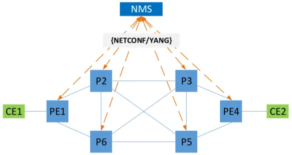
A SPRING node has to be configured to be able to announce its SR capabilities and exchange SR information. Configuration can be done manually using the node Command Line Interface (CLI) or as shown in Fig. 2.5, via a centralized entity such as the Network Management System (NMS) using management protocols [15]. NET-CONF [28] is foreseen as the de facto management/configuration protocol. Therefore, the SPRING working group is working on the definition of a YANG model for the configuration and management of SPRING nodes [29]. A SPRING node requires a minimum set of configuration to be able to communicate with other SPRING nodes. First SR has to be enabled on the node, then the set the SRGB and at least one prefix SID binding.
P2
P6
P5
P3
PE4
PE1
CE1
CE2
NMS
{NETCONF/YANG}Figure 2.5: Configuration of Segment Routing on nodes using a Network Management System (NMS)
In order to simplify the configuration process and to allow the interoperability with non-SPRING nodes a SPRING nodes can act as Segment Routing Mapping Server (SRMS) [30]. Using a set of IGP extension, the SRMS centrally advertises mappings
between prefixes and and Segment Identifiers (SID) on behalf of other SPRING and non-SR-capable nodes. In Fig. 2.6, node P 3 plays the role of SRMS. The SRMS node uses its SPRING IGP instance to advertise the bindings (IGP-Prefix, SID) of P6 and
P5 into the SR domain. SPRING nodes handle the SRMS advertisements as if the
Prefix-SIDs were advertised by the nodes themselves.
P2
P6
P5
P3 SRMPPE4
PE1
CE1
CE2
{NETCONF/YANG}NMS
Manually
<pushing configuration>
CLI NON-SPRING NodesFigure 2.6: Configuration of Segment Routing on nodes using a Mapping Server
As stated before, segment routing does not introduce new protocols. Rather it defines new extensions to the already deployed ones. Once a SPRING node is con-figured with the SR information, it is ready to participate in the SR domain. It advertises its own SR information (SRGB, prefix SID bindings, ) using SR protocol extensions and learns other SPRING node’s information. In an intradomain scenario, SPRING nodes exchange their SR capabilities using one of the two widely deployed IGP protocols (OSPF and ISIS), which have been extended to support the adver-tisement of SR capabilities. In OSPF, SR information (e.g., SRGB, SIDs, etc.) are encoded in a Type Length Value (TLV) format and carried in the opaque Link State Advertisement (LSAs) of type 9, 10 and 11 [31]
2.4
Segment Routing over the MPLS Data Plane
Multiprotocol Label Switching (MPLS) [32] plays a critical role in service provider’s core networks in delivering high-performance next-generation services. Additionally, it is agnostic to the client’s access links because it encapsulates packets in its own header. MPLS has simple data plane. It is based on a fixed size 20-bit labels and three basic operations: POP, PUSH and SWAP. An ingress MPLS node push labels into each packet that enters the MPLS domain. An intermediate MPLS node switches the packet based on his pre-installed forwarding entries and the label carried in the packet’s header. Despite its simple data plane, MPLS’s wide use and the increase of supported services has made its control plane complicated and difficult to trou-bleshooting and to evolve. Traditional MPLS control plane is composed of routing protocols, label distribution protocols and tunnel signaling protocols, causing an im-portant portion of network resources to be consumed just to maintain the protocols soft states. Other issues arise such as synchronization problem between different pro-tocols. SR is regarded as an evolution to MPLS, with its simple, lightweight and SDN-ready control plane. Service providers consider SR as a strong candidate to deliver traditional MPLS services such as Traffic engineering, failure protection (fast reroute), layer two and layer three VPNs.
MPLS’s data plane meets all the requirements to instantiate the SR architecture without any hardware upgrade. A segment is represented by a label, the MPLS header already supports label stacking. Consequently, an SR path is encoded as label stack, and the three basic MPLS forwarding operations are sufficient to forward source-routed packets. Therefore, SR deployment is claimed to be straightforward. For example, to enable SR on one of the network nodes (e.g., PE router), a simple software upgrade is sufficient and there is no need to deploy new hardware. Unfortunately, most of the MPLS Label Switching Routers (LSR) do packets processing using ASICs. ASICs have fixed capacities: for example, if the ASIC can only PUSH a small number of labels, this limits the node’s capacity when expressing SR paths.
In this section, we discuss the MPLS instantiation of SR (SR-MPLS): how SR architectural components are implemented (e.g., Local SID, Global SID, SRGB, etc.). How SR-MPLS control plane interacts and interoperates with other protocols such as LDP and RSVP-TE.
2.4.1
Segment Routing MPLS Terminology
SR instantiation over the MPLS data plane requires the mapping of the generic concepts defined in the SR architecture to the MPLS components and operations. In this section, we detail SR-MPLS specific terminology and how the SR architecture components are implemented in an MPLS data plane.
In SR-MPLS, an SID is an MPLS label. Therefore, for the remainder of the manuscript, the term SID and label are used interchangeably. The SRGB is one range or a concatenation of multiple ranges of local labels allocated by a given node for SR. The advertised SRGB should be large enough to encompass all the global segments. For example, if the network has 100 nodes, then the SRGB size must be greater or equal to 100 (e.g., SRGB == [1000, 1100] or SRGB == [1000, 1049] ∪ [2000, 2049]). To avoid label allocation conflict, no other protocol (e.g., LDP, RSVP-TE) is allowed to use a label inside the SRGB. Additionally, a global unique Index (32-bit integer) is attributed to every global segment. This Index is combined with the nodes SRGBs to compute the labels allocated for a global segments as explained in section 2.4.2.
In addition to the IGP Prefix Segment defined in the generic SR architecture, SR-MPLS defines new SID types that are specific to SR-MPLS networks such as the LDP LSP segment and the RSVP-TE LSP segment. A Global SID is a label within the SRGB and the Local SID is a label outside the SRGB. For example:
• A Prefix-SID is a global SID, which is attached to an IGP-Prefix (i.e., IP address). It is a label that take its values within the SRGB. The Node-SID is a special case of the Prefix-SID; it is a label that identifies a specific network node. It is attached to one of the node’s loopback addresses.
• An Adj-SID is a label that identifies the adjacency between two nodes. Gener-ally advertised as a local SID unless decided otherwise. The Group-Adj-SID is a special case of the Adj-SID. It is used for load balancing purposes over all the links/interfaces tagged with the same Group-Adj-SID.
2.4.2
SR-MPLS Global Segment Implementation
SR instantiation over the MPLS data plane translates an SID to a standard MPLS 20-bit label. SR paths are encoded as a stack of labels that get pushed into each packet header to construct the source-routed path. Having a consensus on how to
![Table 2.2: Node-SIDs computation with different Global Block for each node PE1 SRGB [1000,2000] Node Node-SID PE1 1001 P2 1002 P3 1003 PE4 1004 P5 1005 P6 1006 P2 SRGB [3000,4000]NodeNode-SIDPE13001P23002P33003PE43004P53005P63006 PE4 SRGB [7000,8000] Node](https://thumb-eu.123doks.com/thumbv2/123doknet/11573865.297707/44.892.238.700.225.628/table-node-computation-different-global-block-nodenode-sidpe.webp)