HAL Id: hal-01888402
https://hal.archives-ouvertes.fr/hal-01888402
Submitted on 5 Oct 2018
HAL is a multi-disciplinary open access
archive for the deposit and dissemination of
sci-entific research documents, whether they are
pub-lished or not. The documents may come from
teaching and research institutions in France or
abroad, or from public or private research centers.
L’archive ouverte pluridisciplinaire HAL, est
destinée au dépôt et à la diffusion de documents
scientifiques de niveau recherche, publiés ou non,
émanant des établissements d’enseignement et de
recherche français ou étrangers, des laboratoires
publics ou privés.
Expanded Beam Connectors for Single Mode Optical
Fiber Sensor Applications in Harsh Environment
Xavier Insou, Lionel Quetel, Sébastien Claudot, Monique Thual
To cite this version:
Xavier Insou, Lionel Quetel, Sébastien Claudot, Monique Thual.
Expanded Beam Connectors
for Single Mode Optical Fiber Sensor Applications in Harsh Environment.
26th International
Conference on Optical Fiber Sensors (OFS-26), Sep 2018, Lausanne, Switzerland.
pp.TuE31,
Expanded Beam Connectors for Single Mode Optical
Fiber Sensor Applications in Harsh Environment
Xavier Insou 1,3, Lionel Quétel 2, Sébastien Claudot 3, Monique Thual1 1 Univ Rennes, CNRS, Institut Foton, UMR6082, 6 rue de Kérampont, F-22305 Lannion, France
2 IDIL Fibres Optiques, 21 rue Louis De Broglie 22300 Lannion, France 3 Souriau-Sunbank - Esterline ECT, RD323, 72470 Champagné, France
Author e-mail address: [email protected]
Abstract: We propose an expanded beam micro lens in standard connectors, compliant with
harsh environment connections. Low Insertion loss, high return loss and relaxed alignment tolerances compared with SMF are demonstrated in C and O band. We give two examples of harsh environment optical fiber sensor applications.
OCIS codes: (200.4650) Optical Interconnects; (060.2430) Fibers, single mode; (280.4788) Optical sensing and
sensors.
1. Introduction
Connections in harsh environment is a key element in the composition of the measurement line in single mode optical fiber sensors. For example, in the ASHLEY European project (Avionics Systems Hosted on a distributed modular electronics Large scale dEmonstrator for multiple tYpes of aircraft), different optical sensors will be implanted in multiple types of aircrafts. One of the biggest challenge is often to couple light through the sensor device [1]. A solution to realize harsh single mode connectors is to increase the mode field diameter at the output of the fiber. This extension is generally obtained by using ball or hemispherical lenses at the end of the fibers [2]. This technique is interesting but not optimized in terms of insertion loss and return loss, it also needs a specific connector housing. In this article, we propose an innovative solution to increase the beam diameter with low insertion loss, low reflectance and good repeatability by using standard connectors. First, we give the concepts and principle of this solution, then we integrate it in standard connectors and measure the sensitivity to different contaminations. Finally, examples of optical fiber sensor demonstrators pointing out the interest of these expanded beam connectors are given.
2. Theoretical concepts and principle of the expanded beam connectors
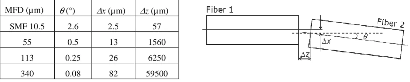
Due to their very small mode field diameters (MFD), single mode fibers are very sensitive to contaminants, laser power and alignment defaults either lateral ∆x, axial ∆z or angular θ when injecting signal from one fiber to one another whatever the application as illustrated in Fig.1. Expanded beam micro-lenses are very useful to relax lateral and axial positioning tolerances as can be seen in Table 1, where defaults that lead to 1 dB excess loss are calculated with equations extracted from ref [3] for different kinds of expanded Gaussian beams whose MFD are 55, 113 and 340 µm, compared with SMF of 10.5 µ m MFD at a wavelength of 1550 nm.
The lateral positioning tolerances is relaxed from 2.5 to 82 µ m, the axial one from 57 to 59500 µm with a 340 µ m MFD expanded beam compared with SMF. But the angular alignment decreases with expanded beam from 2.6 to 0.08°. Then a MFD around 55 to 110 µ m is a good tradeoff to relax lateral and axial positioning tolerances without decreasing the angular ones compared with SMF.
Table 1: tolerances for 1 dB excess loss @ λ=1550nm
MFD (µ m) θ (°) ∆x (µm) ∆z (µ m)
SMF 10.5 2.6 2.5 57
55 0.5 13 1560
113 0.25 26 6250
340 0.08 82 59500
Fig. 1. Positioning defaults between two fibers
Moreover, expanded beam are less sensitive to high power and contaminants such as dust, oil and water for harsh environment applications.
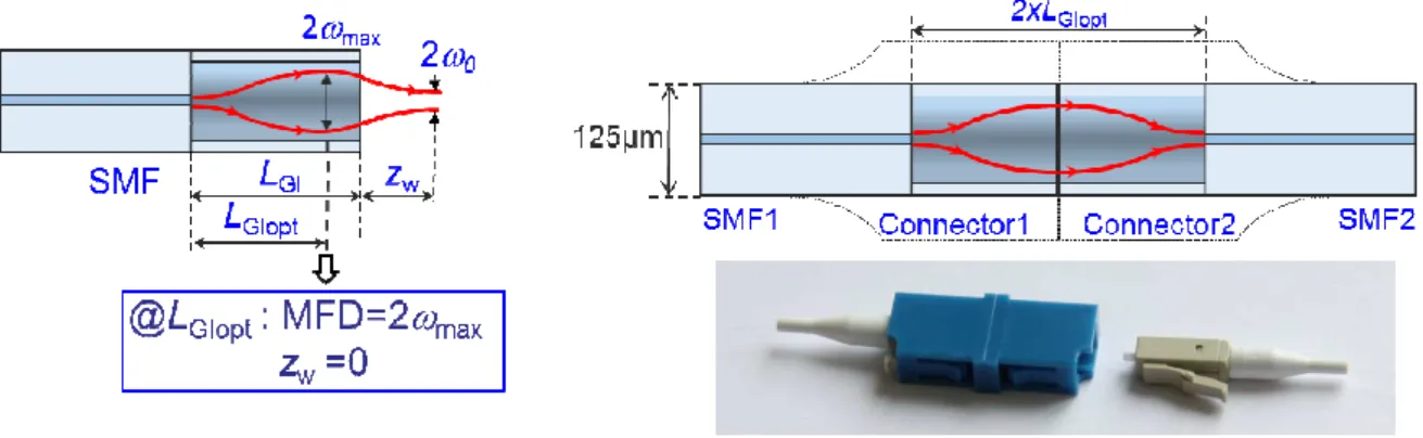
A solution to achieve such an expanded beam at a SMF fiber output consists in splicing a parabolic lateral graded index fiber (GIF) to a SMF and to cut the GIF, at a length LGIopt from the splicing, where the Gaussian
beam size 2ω is expanded at its maximum 2ωmax as can be seen in Fig. 2. In this case the wave front is plane at the fiber output and the working distance zw is null. This configuration is appropriate for expanded beam
connectors compliant with harsh conditions single mode fiber transmissions of at least 10 Gbit.s-1 as already
demonstrated in 55 µ m MFD LC connectors as can be seen in Fig. 3. Coupling loss as low as 0.5 dB from O to C band have been achieved for Return Loss as high as 65 dB [4].
Fig. 2. Principle of the SMF GIF expanded beam micro lens Fig. 3. Expanded beam LC connectors
Fig. 4 shows a photo of the 55 µ m expanded beam at a SMF-GIF output compared with a SMF pointing out the expanded beam and the 125 µ m outer diameter that remains constant, allowing the use of standard connectors (see Fig. 3).
Fig. 4. Optical microscope view of a SMF-GIF output compared with a SMF when illuminated by visible light
We have also pointed out the best conditions to relax lateral and axial positioning tolerances without going down to critical angle tolerances and to achieve both high coupling efficiency and low reflectance with very tolerant fabrication process of this kind of expanded beam micro lenses [5].
Those expanded beam micro lenses can also be used in optical fiber sensor applications since functions can be added in between the fibers thanks to the relaxed axial and lateral positioning tolerances. For instance 55 MFD expanded beam fibers can be separated from more than 1.5 mm with only 1 dB excess loss as can be seen in Table 1. Moreover, the micro lens can also be designed to achieve a wide range of MFD 2ω0 and working distances zw depending on the length LGI and opto geometric parameters of the GIF as can be seen in Fig. 5
where the MFD and working distance are plotted as a function of relative LGI length to LGIopt as developed in [4,
5]. The maximum MFD is 55 µ m for a null working distance but it can achieve a wide range of MFD comprised between 10.5 to 55 µm with working distances in a range of 0 up to 500 µm allowing a wide range of applications comprising optical fiber sensors.
Fig. 5: (a) Analytical and BPM calculation of MFD and working distance for a given GIF profile
125µm
55µm
SMF-GIF
SMF
3. Integration of expanded beam fibers in standard connectors
These expanded beam fibers can easily be integrated in standard connectors such as FC, ST or even a multipoint one, as can be seen in Fig. 6 showing a picture of a connector with two expanded beam fibers. The fibers are glued in connector ferrules with a standard procedure. The ferrule are polished using conventional optic fiber polishing machines compatible with mass production. This operating mode authorizes repeatability in terms of Insertion Loss and Return Loss.
Fig. 6: Example of multipoint connectors with expanded beam fiber
4. Contamination effect (oil, water, dust)
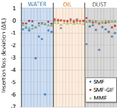
The robustness of the SMF GIF interface has been evaluated over three contaminants: oil (0.03ml droplet), water (0.03ml droplet) and dust particles in comparison with SMF and MMF (OM3 multimode fiber), as shown in Fig. 7. The insertion loss deviation compared with contaminant free connections in LC connectors is plotted for 10 mating cycles each time in Fig. 7. The physical contact technology is able to exclude the liquid from the interface due to the high pressure of the spring loading which leads to good optical results in water contamination. Sometimes some liquid residue is left, leading to higher losses for a single mode interface with an oil droplet for instance. With solid particle contamination, it is a matter of statistical particle distribution over the core area; when the remaining area for passing light becomes smaller, the insertion losses increase accordingly. The results in Fig. 7 show that the SMF GIF is an interface with similar robustness compared to a MMF in the presence of contamination and better than SMF.
Fig. 7: Insertion loss deviation (∆IL) recorded over oil contamination (MIL-PRF-7808), water contamination and dust particle contamination (talc powder 10 microns) compared with contaminant free connections, for a SMF GIF LC connection, a SMF LC
connection and a MMF LC connection, each time with 10 mating cycles
Such a behavior makes utilization of such connectors in harsh environments very useful especially in sensor applications. Moreover thanks to the high misalignment tolerances as demonstrated in paragraph 2, these expanded beam connectors are less sensitive to thermal induced mechanical expansion.
5. Examples of optical sensor applications where the expanded beam connectors can be used
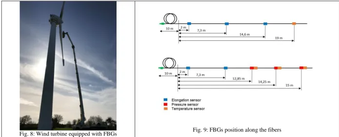
The study of the dynamic behavior of wind turbine blades by using Fiber Bragg Gratings (FBGs) has been performed by IDIL Fibres Optiques. Arrays of FBGs sensors were used to measure temperature, elongation and pressure. The FBGs were connected to the interrogator with optical connectors. Fig. 8 represents the wind turbine equipped with FGBs arrays. These FBGs positions along the fibers are given in Fig. 9.
This work has been done during the collaborative research project AeroGust (Aeroelastic Gust Modelling) between industry and academia funded by the European Union’s Horizon 2020. Humidity, salt mist, oil and vibrations make the use of the proposed expanded beam connectors unavoidable for long term reliability.
IDIL Fibres Optiques has also realized swell experiments in IFREMER Labs with a dynamic scattering processes measurement using Brillouin effect.
The fiber was fixed on a neoprene film which was floating on the salt water as represented in Fig. 10. Salt water, dirt and vibrations make the use of expanded beam connectors unavoidable.
Fig. 10 Optical fiber laying on the water surface
4. Conclusions
We have theoretically analyzed and experimentally demonstrated the use of innovative expanded beam fibers integrated in standard connectors for SM optical sensor applications with low insertion loss and low reflectance. The connectors authorize transmissions of at least 10 Gbit.s-1, can be used in a broad range of wavelengths
(>200 nm) and should also support higher power than SMF (up to 100 W expected). Due to its specifications, such connectors can be used in a large range of applications including moving pieces such as in rotating connectors.
References
[1] Liang Qiu, Michael E. Teitelbaum, Keith W. Goossen, Dirk Heider, Daniel J. O’Brien, Eric D. Wetzel, “Normal free space coupling to fiber Bragg grating sensors”, Proceedings of SPIE - The International Society for Optical Engineering 7292, March 2009.
[2] D. Childers, M. Hughes, S. Lutz, and T. Satake, “Design and performance of expanded beam, multi-fiber connectors”, presented at the Optical Fiber Communication Conf. (OFC), Los Angeles, C.A., US 2015, paper ThC1, Invited paper.
[3] M. Saruwatari and K. Nawata, “Semiconductor laser to single-mode fiber coupler”, Applied Optics, vol. 18, no. 11, pp. 1847-1856, June 1979.
[4] S. D. Le, M. Gadonna, M. Thual, L. Quetel, J-F. Riboulet, V. Metzger, D. Parker, A. Philippe, and S. Claudot, “Reliable Expanded Beam Connector Compliant with Single-mode Fiber Transmission at 10 Gbit/s”, oral session, section D1.5 W4B.5, Los Angeles, Optical Fiber Communications 2015.
[5] S. D. Le, P. Rochard, J.-B. Briand, L. Quétel, S. Claudot, and M. Thual, “Coupling Efficiency and Reflectance Analysis of Graded Index Expanded Beam Connectors”, Journal of Ligthwave Technology, Vol. 34, N°9, pp. 2092-2099, May 1, 2016.