THÈSE
En vue de l’obtention du
DOCTORAT DE L’UNIVERSITÉ DE TOULOUSE
Délivré par l'Université Toulouse 3 - Paul Sabatier
Présentée et soutenue par
Le 10 décembre 2019
Spark Plasma Sintering de composites base titane renforcés par
Ecole doctorale : SDM - SCIENCES DE LA MATIERE - Toulouse Spécialité : Sciences et Génie des Matériaux
Unité de recherche :
CIRIMAT - Centre Interuniversitaire de Recherche et d'Ingénierie des Matériaux
Thèse dirigée par
Jury
M. Yann LEPETITCORPS, Rapporteur M. Frédéric SCHOENSTEIN, Rapporteur Mme Florence PETINARI-STURMEL, Examinatrice
M. Claude ESTOURNES, Directeur de thèse
Mme Sophie GUILLEMET-FRITSCH, Co-directrice de thèse
Claude ESTOURNES et Sophie GUILLEMET-FRITSCH
Glenda Tsholofelo MOTSI
2 ‘‘it always seem impossible until it’s done’’ Nelson Mandela
4
Acknowlegdements
Foremost, I would like to express my sincere gratitude to the director of ‘‘Centre Inter-universitaire de Recherche et d’Ingénierie des Matériaux (CIRIMAT)’’, Prof. Christophe Laurent for his warm welcome and allowing me to do my PhD Thesis in the laboratory. I would like to thank Prof. Yann Lepetitcorps and Prof. Frederic Schoenstein for accepting to be rapporteurs of this thesis. I also thank Prof. Florence Pettinari-Sturmel for being the president during my defense presentation.
I thank my mentor Prof. Peter A. Olubambi for his assistance and encouragement in obtaining AESOP+ scholarship to study in France.
Special thanks to the AESOP+ project for giving me an opportunity to pursue my doctorate programme abroad.
My sincere gratitude to my supervisors Dr. Sophie Guillemet-Fritsch and Dr. Claude Estournès for their warm welcome at CIRIMAT’’. Your continuous support, motivation, guidance and insightful comments throughout my PhD study are highly appreciated.
Many thanks to the staff of CIRIMAT Marie-Claire Barthelemy, Geoffroy Chevallier, Benjamin Duployer,Raphaël Laloo, Jean-Jacque Demain and Vincent Baylac for teaching me operate research equipment independently, the technical skills I have acquired are most valuable to me.
I thank Dr. Babatunde Obadele, Mr. Jeremiah Akinribide and Mr. Olukayode Akinwamide at the Center for Nanoengineering and Tribocorrosion in the University of Johannesburg for his assistance during the tribocorrosion experiments.
Special thanks to TIMET-Savoie for their generous assistance in analysing interstitial elements in my powders, Marion Technologie for trace elements analysis with ICP-OES, Alexandre Freulon for his assistance in etching samples, Claudie Josse and Maria-Teresa Hungria-Hernandez for SEM/FIB and TEM analysis of my samples.
I thank my fellow doctoral students, Precious Radingoana, Ugras Kus, Juliano Schorne-Pinto, Arnaud Fregeac, Andréas Flareau, Yannick Thebault and Clément Genet for your cooperation and of course friendship.
Last but not the least, I would like to thank my family: my mother Caroline Dikeledi Motsi for being there always and giving me support during my academic years, my husband and daughters Wola Ladipo, Kgalalelo and Onthatile Motsi for your love and patience, my sister and niece Annah and Ontlametse Motsi, my grandmother and late grandfather Annah and Cornelius Motsi, I appreciate you all.
6
Table of contents
Nomenclature ... 10
General introduction ... 12
CHAPTER 1: Literature review ... 19
1.0 Pure titanium ... 21
1.1. Crystal structure ... 21
1.1.1 Alloying elements for commercial pure titanium ... 22
1.1.1.1 Oxygen ... 23
1.1.1.2 Nitrogen ... 24
1.1.1.3 Carbon ... 25
1.1.1.4 Hydrogen ... 26
1.1.2 Microstructure of pure titanium ... 27
1.1.3 Alloying elements effect on CP-Ti mechanical properties ... 28
1.1.4 Sintering methods ... 29
1.1.5 Sintering of titanium, densification and mechanical properties ... 30
1.2. Metal Matrix Composites ... 32
1.2.1 Titanium Matrix Composites (TMC) ... 34
1.2.1.1 Continuously reinforced TMCs ... 34 1.2.1.2 Discontinuously reinforced TMCs ... 35 1.2.1.3 Ti-TiB2 composite ... 36 1.2.1.4 Ti-TiB composites ... 38 1.2.1.5 Ti-TiC composites ... 41 1.2.1.6 Ti - B4C composites ... 44 1.2.2 Summary ... 52 1.3 Tribology ... 53
1.3.1 Wear behaviour of Ti-TiB2/TiB, Ti-TiC and Ti - B4C composites ... 54
1.3.1.1 Summary ... 57
1.4 Corrosion ... 57
1.4.1 Corrosion behaviour of Ti-TiB2/TiB, Ti-TiC, TiC-TiB2 and Ti-B4C composites ... 58
1.4.2 Summary ... 61
1.5 Tribocorrosion ... 62
1.5.1 Definition of tribocorrosion ... 62
7
1.5.3 Tribocorrosion behaviour of TMCs ... 64
1.5.4 Summary ... 67
CHAPTER 2: Materials and Experimental procedures ... 69
2.1 Materials of study ... 71
2.2 Elemental analysis by ICP-OES and Instrumental gas analysis ... 71
2.3 X-ray Diffraction ... 71
2.4 Scanning electron microscope ... 71
2.5 Particle sizes ... 71
2.6 Turbula mixing ... 72
2.7 Spark Plasma Sintering ... 72
2.8 Relative density ... 73
2.9 Hardness testing ... 74
2.10 Microstructure analysis by SEM/FIB and TEM ... 74
2.11 Corrosion tests ... 75
2.12 Tribocorrosion tests ... 75
2.13 Characterisation of tribocorroded samples ... 76
CHAPTER 3: Sintering and characterization of CP-Ti powders ... 78
3.0 Introduction ... 80
3.1 Characterizations of CP-Ti powders ... 81
3.2 Temperature variation during sintering ... 82
3.3 Effect of sintering temperature and pressure on densification ... 83
3.4 Effect of sintering temperature and pressure on the microstructure ... 84
3.5 Effect of sintering temperature and pressure on Vickers hardness ... 90
Summary ... 91
CHAPTER 4: Sintering, characterization and reaction mechanisms of Titanium Matrix Composites ... 94
4.0 Introduction ... 96
4.1Characterization as-received CP-Ti (25.9μm) and B4C powders ... 97
4.2 Characterization of mixed CP-Ti (25.9μm) and B4C powders ... 98
4.3 Synthesis and densification of TMCs ... 101
Summary ... 106
4.4 Microstructural evolution with temperature and pressure ... 107
Summary ... 111
8
Summary ... 120
4.6 Reaction mechanisms for Ti5wt%B4C with sub-micron B4C(1.67µm) particles ... 121
4.7 Dwell time effect on the microstructure ... 125
4.8 Relation between reinforcing phase’s content and size to the Vickers hardness ... 135
4.9 Reaction kinetics in TMCs by SPS ... 143
Summary ... 149
CHAPTER 5: Corrosion and Tribocorrosion of Titanium Matrix Composites (TMCs) .... 151
5.0 Introduction ... 153
5.1 TMCs for corrosion and tribocorrosion studies ... 154
5.2 Open circuit potential in 3.5%NaCl for Ti and TMCs sintered at 1000°C and 1100°C .. 156
5.3 Potentiodynamic polarization in 3.5%NaCl for Ti and TMCs sintered at 1000°C and 1100°C ... 159
5.4 Open circuit potential under sliding conditions in 3.5%NaCl for Ti and TMCs sintered at 1000°C and 1100°C ... 164
5.5. Potentiodynamic polarization behaviour under sliding in 3.5%NaCl for Ti and TMCs sintered at 1000°C and 1100°C ... 170
5.6 Wear tracks morphology ... 176
Summary ... 184
General conclusion ... 186
Appendix I ... 204
I.I Mass required for sintering Ti5wt%B4C composites ... 204
I.II Theoretical density of sintered Ti5wt%B4C composites ... 204
I.III Theoretical volume percentage of reinforcing phases in Ti5wt%B4C ... 206
Resumé ... 209
10
Nomenclature
COF
CP-Ti Friction Coefficient Commercial Pure Titanium
Ecorr Corrosion potential
EDS Energy Dispersive Spectrometry
EELS EDX spectrometer and a loss of energy spectrometer
FFT Fast Fourier Transform
FIB Focus Ion beam
Gr Graphite
HP Hot Pressing
Icorr Corrosion current density
ICP-OES Inductively Coupled Plasma - Optical Emission Spectrometry
OCP Open Circuit Potential
PDP Potentiodynamic polarisation
PSD Particle Sizes and Distribution
RIR Reference Intensity Ratio
SEM Scanning Electron Microscope
SPS Spark Plasma Sintering
TEM Transmission Electron Microscope
12
General introduction
13 Titanium and its alloys are well-known throughout engineering applications for their combined desirable properties of high specific strength to weight ratio, low density, biocompatibility and relatively good corrosion resistance (Welsch et al., 1993). The production of bulk titanium involves expensive complex Kroll’s processes such as refining, distillation and dissolution (Lütjering et al., 2007a). These processes are performed using specific devices in a vacuum environment to avoid contamination by gaseous phases, especially oxidation because of titanium high affinity to oxygen (Lütjering et al., 2007a; Shon
et al., 2014a) . In addition, the high energy consumption, the initial high cost of titanium
tetrachloride and that of reducing agents (pure magnesium and sodium) contribute titanium high cost and thus its limitation of use in other applications such as automobile (Shon et al., 2014a; Welsch et al., 1993). The latter product is in form of rolled plates which are further processed. Due to the high cost of production, these classes of materials are extensively used in high added value industries such as the aerospace, biomedical and marine applications (Zadra et al., 2008).
In comparison to other commonly used engineering materials high purity titanium has a melting point of 1668°C, higher than the one of Fe (1538°C), Al (660°C) and Ni (1455°C) as illustrated in Table 1 (Lütjering et al., 2007a). The much higher melting temperature of titanium (1670°C) as compared to aluminum (660°C), the main competitor in light weight structural applications, give titanium a definite advantage for application temperatures above 150°C (Lütjering et al., 2007a). Pure titanium has tensile strength of 240MPa, toughness in the range 99-140MPa-m1/2, Vickers hardness of 60HV, modulus of elasticity of 120GPa and high friction coefficient (0.68 - 0.8) (Donachie, 2000). As a result of their light-weight coupled with moderately high strength and outstanding corrosion resistance properties, these have made titanium and its alloys candidate material for other engineering applications such as automotive, offshore, aeronautics and energy industries (Cheng et al., 2012). However, conventional Ti and its alloys exhibit inferior wear resistance and suffer considerable loss in mechanical strength (Balaji et al., 2015). These limitations prevent titanium in many engineering applications were both corrosion and wear may be encountered (Toptan et al., 2016).
14 Table 1. Material characteristics of titanium compared to other structural metallic materials based on Fe, Ni, and Al(Lütjering et al., 2007a)
Ti Fe Ni Al
Melting temperature (°C) 1670 1538 1455 660
Allotropic transformation (°C) 882
β → α 912 γ →α - -
Crystal structure BCC→HCP FCC→BCC FCC FCC
Room temperature E(GPa) 115 215 200 72
Yield stress level (MPa) 1000 1000 1000 500
Density (g/cm3) 4.5 7.9 8.9 2.7
Comparative corrosion
resistance Very high Low Medium High
Comparative reactivity with O2 Very high Low Low High
Comparative price of metal Very high Low High Medium
Incorporation of hard ceramic particles or fibers reinforcements into titanium based matrix can significantly improve its wear resistance by direct strengthening effect taking place due to the ability of the reinforcing phases to carry the load (Blau et al., 2007; Prakash et al., 2016). Also by indirect strengthening, taking place by alterations on the metallic matrix structure, such as induced dislocations, Orowan strengthening, or grain size refinement and modification of the matrix microstructure as a consequence of the addition of the reinforcing phase (Chawla et al., 2006). The demand for the use of titanium matrix composites (TMCs) is attributed to the availability of the ever-evolving sources of relatively inexpensive reinforcements and the frequent development of the processing routes which results in reproducible microstructures and properties (Ajayan et al., 2006). Powder metallurgy techniques have been found as one of energy efficient ways for production of TMCs or other materials. Several techniques exist to densify but the use of innovative Spark Plasma Sintering (SPS) method has been the most favourable. The SPS process combine the effect of uniaxial pressure and Joule effect produced from pulsed electric current passing through sintering tool and a conductive powder. Thus, faster heating rates can be achieved and powders can be rapidly densified within short period of time as reported in literature (Abedi et
al., 2016; Kus et al., 2016; Locci et al., 2006; Munir et al., 2006; Orru et al., 2009; Zadra et al., 2013)
TMCs are traditionally fabricated by ex-situ methods, whereby pure TiB2 and TiC particulates are separately prepared and later added to Ti matrix for production of Ti-TiB2/TiB and Ti-TiC composites respectively (Ajayan et al., 2006). With this method, undesirable second phases
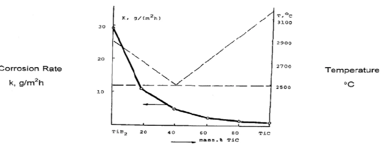
15 may be formed in the matrix-reinforcement interphase and resulting in poor interfacial bonding (Ajayan et al., 2006). The second phases may act as stress concentrators leading to deterioration of mechanical properties. Moreover, synthesis of TMCs using pure TiB2 and TiC which have high melting points of 2970°C and 3054°C respectively, make the sintering difficult due to their low self-diffusion coefficients (Wang et al., 2012). However, densification of 99% was achieved when the composition ratio was 85%TiB2: 15%TiC, processed by high pressure (3GPa) sintering techniques at higher temperatures (2250-2500°C) (Vallauri et al., 2008).
Alternatively TMCs have been commonly fabricated by in-situ methods, most favourably using SPS technique. This method involves simultaneous synthesis and densification in one step at relatively low temperatures (Dudina et al., 2013). The reinforcing phases synthesized in-situ by exothermic reactions between titanium and a constituent element (B4C) often result in clean interface and strong interfacial bonding (Ajayan et al., 2006; Campbell, 2010). Synthesis of TiC, TiB2 and TiB can be achieved when a complete chemical reaction is reached.
Although in-situ method tends to be favourable in terms of reduced fabrication cost, energy consumption and cheap B4C powders, there are challenges encountered during fabrication process. These include the ability to control the size of the reinforcement phase because the reaction kinetics of the reactants is not the same throughout. Hence, great care must be taken on the selection of the reactant’s particles size (considering the high cost), mixing conditions and sintering parameters. Such that, when reactants with micron size particles are used in SPS, prolonged sintering time and very high temperatures (1100 to 1400°C) are required to reduce the amount of unreacted particles, in contrast to sub-micron size particles (<1100°C). TMCs fabricated from micro-sized reinforcing phases were reported to be characterized by incomplete reaction consisting of B4C, TiB2, TiB, TiB clusters and porosity found around B4C agglomerates (Ni et al., 2006; Toptan et al., 2016). These microstructural characteristics may
have adverse effect on the composites properties. Porosity may act as stress concentrator, high corrosion rates may results from porosity, unreacted B4C may de-attach from matrix during rubbing and act as third-body abrasive accelerating wear rates (Toptan et al., 2016). In contrast to sub-micron sized reactants, the increased of their surface area, compare to the micron ones, leads to increased reactions kinetics which requires less periods during sintering
16 and complete reaction may be achieved. In this regard, when proper fabrication variables are chosen, the resultant composites have good microstructural characteristics such as clean interface between the matrix and reinforcing phase, the intermediate phases are eliminated and also good dispersion of reinforcing phase is achieved.
Nevertheless, the synergy effect of TiC, TiB2 and TiB on tensile strength, elongation and hardness from in-situ synthesized TMCs has been widely explored (Geng et al., 2008; Li et
al., 2016; Rahoma et al., 2015). The literature based on corrosion and especially
tribocorrosion behaviour is however lacking. Owing to the emerging technological applications of TMCs in harsh environments, such as automotive, marine, chemical and petrochemical industries (Mathew et al., 2009) where corrosion and tribocorrosion are encountered, it is important to contribute knowledge on the corrosion and tribocorrosion performance of TMCs based on TiC, TiB2 and TiB to this research field.
This work is focused on the elaboration of titanium based composites reinforced with TiC, TiB2 and TiB phases by reactive spark plasma sintering. Our work will be focused on the optimisation of the densification parameters, on the understanding of the reaction kinetics, microstructure evolution, mechanical and tribocorrosion behaviour.
Thus the objectives are multiple:
• To simultaneously synthesize and consolidate TMCs with homogenously distributed TiB and TiC phases in the titanium matrix
• Study a detailed analysis of the in-situ reaction mechanisms and kinetics • To improve the tribocorrosion properties of Ti by TiB and TiC.
The thesis is organised as follows:
In the first chapter, literature based on sintering of titanium and its composites, obtained microstructures and properties is reviewed. The second chapter contain materials of study, characterisations, sintering by SPS and tribocorrosion experiments. The third chapter present the results obtained for SPS of pure titanium, the effect of sintering parameters and interstitial element are thoroughly discussed. The fourth chapter present the results and discussion for densification of titanium matrix composites and reaction kinetics involved using reactants with varying particles sizes. The fifth chapter present the results and
17 discussion obtained for corrosion and tribocorrosion experiments of titanium matrix composites.
19
CHAPTER 1: Literature review
20
Table of contents
1.0 Pure titanium ... 21
1.1. Crystal structure ... 21
1.1.1 Alloying elements for commercial pure titanium ... 22
1.1.1.1 Oxygen ... 23
1.1.1.2 Nitrogen ... 24
1.1.1.3 Carbon ... 25
1.1.1.4 Hydrogen ... 26
1.1.2 Microstructure of pure titanium ... 27
1.1.3 Alloying elements effect on CP-Ti mechanical properties ... 28
1.1.4 Sintering methods ... 29
1.1.5 Sintering of titanium, densification and mechanical properties ... 30
1.2. Metal Matrix Composites ... 32
1.2.1 Titanium Matrix Composites (TMC) ... 34
1.2.1.1 Continuously reinforced TMCs ... 34 1.2.1.2 Discontinuously reinforced TMCs ... 35 1.2.1.3 Ti-TiB2 composite ... 36 1.2.1.4 Ti-TiB composites ... 38 1.2.1.5 Ti-TiC composites ... 41 1.2.1.6 Ti - B4C composites ... 44 1.2.2 Summary ... 52 1.3 Tribology ... 53
1.3.1 Wear behaviour of Ti-TiB2/TiB, Ti-TiC and Ti - B4C composites ... 54
1.3.1.1 Summary ... 57
1.4 Corrosion ... 57
1.4.1 Corrosion behaviour of Ti-TiB2/TiB, Ti-TiC, TiC-TiB2 and Ti-B4C composites ... 58
1.4.2 Summary ... 61
1.5 Tribocorrosion ... 62
1.5.1 Definition of tribocorrosion ... 62
1.5.2 Tribocorrosion model for degradation phenomena ... 63
1.5.3 Tribocorrosion behaviour of TMCs ... 64
21
1.0 Pure titanium
1.1. Crystal structure
The crystal structure of pure titanium from room and temperatures up to 882°C has a hexagonal closed packed (HCP) crystal structure also known as alpha (α) phase. Above 882°C, which defines the transus temperature (Tβ), it transforms to a body centred cubic (BCC) crystal structure, the beta (β) phase. The atomic unit cell for the α-Ti and β-Ti with their closely packed crystal planes are shown in the Figure 1.1 (Leyens et al., 2003). The parameters of α-Ti and β-Ti phases are listed in Table 2. As shown in Table 2 α-Ti and β-Ti have densities of 4.51g/cm3 at 20°C and 4.35g/cm3 at 885oC with atomic packing factors of 78% and 68% respectively (Callister et al., 2007; Welsch et al., 1993). As a result, during
polymorphic transformation occurring at the transus temperature there is a slight volume expansion of 3.7% during heating and slight contraction of -3.34% during cooling (Qian et
al., 2015).
Table 2. Structure characteristics of pure Titanium (Leyens et al., 2003; Welsch et al., 1993).
Phase Space
group structure Crystal packing Atomic factor
Lattice
parameters Lattice angles Density
α-Ti P63/mmc HCP 78% a = b = 0.295nm c = 0.468nm c/a=1.58 α = β = 90° γ = 120° 4.51 g/cm3@ 20°C β-Ti lm-3m BCC 68% a = b = c = 0.332 α = β = γ = 90° g/cm4.35 3 @ 885°C
22 Figure 1.1. Crystallographic structures of titanium a) HCP (α-Ti) and
b) BCC (β-Ti) (Leyens et al., 2003)
1.1.1 Alloying elements for commercial pure titanium
In the HCP and BCC crystal structures of titanium, the alloying interstitial elements occupy tetrahedral and octahedral interstitial sites as shown in Figure 1.2 (Fukai, 2006). HCP crystal structure has 4 tetrahedral and 2 octahedral interstitial sites , while BCC crystal structure has 12 tetrahedral and 6 octahedral interstitial sties (Vasanthakumar et al., 2018). The radius of the tetrahedral and octahedral site for the HCP crystal structure are 0.33Å and 0.61Å respectively, and for the BCC is 0.44Å for the tetrahedral site (Cordero et al., 2008). Interstitial elements H, O, N and C in increasing order having atomic radii of 0.31, 0.66, 0.71 and 0.76Å occupy tetrahedral and octahedral interstitial sites respectively, while Fe atom with a larger atomic radius of 1.32Å atom may substitute titanium atoms (radius= 1.6Å) from the unit cell (Conrad, 1981; Cordero et al., 2008). Among the alloying elements C, O, N and Fe are the α-Ti phase stabilisers and H is the β-Ti phase stabilizer. Oxygen has the highest solid solubility of 30at.% in α-Ti followed by 19at.% of nitrogen, 2at.% of carbon and 8at% hydrogen (Conrad, 1981) according to the binary phase diagrams in Figures (1.3, 1.4, 1.5 & 1.6).
a
23 Figure 1.1. Tetrahedral and octahedral interstitial sites in HCP and BCC crystal structures.
Adapted from (Fukai, 2006)
1.1.1.1 Oxygen
Titanium has a strong chemical affinity for oxygen and often forms an oxide layer on the surface of titanium and enhances corrosion resistance. This oxide layer forms at room temperature and thickness rapidly at elevated temperatures when heated in air. At temperatures exceeding 500°C the oxidation resistance of titanium decreases rapidly and the metal becomes highly susceptible to embrittlement by oxygen. In order to minimise oxygen contamination in titanium and its alloys the production has to be performed in a controlled atmosphere such as vacuum or inert gas atmosphere (Donachie, 2000).
Oxygen is an α-Ti stabilizer because of its high maximum solubility of 30at.% at temperature above 600°C (Kwasniak et al., 2014) and it increases the α to β allotropic transformation temperature as shown in Figure 1.3 (Welsch et al., 1993). It is important to consider oxygen content when analysing mechanical properties of α-Ti. Oxygen diffusion in α-Ti modifies lattice parameters and this has an effect on the mechanical properties. Baillieux et al. (2015) studied the effect of oxygen diffusion on the crystallographic evolution of α-Ti using
Ti C, H, O and N Tetrahedral sites: α-Ti (HCP) β-Ti (BCC) 4 12 Octahedral sites: 2 6 β-Ti (BCC) α-Ti (HCP)
24 synchrotron X-ray diffraction at elevated temperature and varied dwell time. They analysed the lattice parameters on the cross section area from the oxide layer to the center of a sample They observed that the lattice parameters c and a , the ratio c/a and the hardness gradually increase as the distance from the oxide metal interface decreases for samples heat-treated in air. Moreover due to change in the lattice parameters there is also a slight unit cell volume expansion of about 0.00013nm3 (Wasz et al., 1996).
Figure 1.3. Ti-O binary diagram (Welsch et al., 1993)
1.1.1.2 Nitrogen
Similar effects have been obtained for α-Ti phase stabilisers nitrogen (Figure 1.4) (Galvanetto
et al., 2001; Vasanthakumar et al., 2018). Interstitial nitrogen reacts much slower with
titanium than oxygen but forms a very hard TiN or Ti2N phases with good tribological properties. Thus, titanium nitriding is normally done to improve the surface properties of titanium for good surface hardness and tribology properties. But excessive nitrogen diffusion in titanium may cause embrittlement (Zhecheva et al., 2005). Galvanetto et al. (2001) investigated the formation of nitride phases obtained by reactive plasma spraying of α-Ti powder in a nitrogen-containing plasma gas on 304L steel. The phases formed after coating consisted of α-Ti, TiN and Ti2N layers and the lattice parameters calculated were compared with the JCPDS standards and from literature. The calculated lattice parameters a and c with reference to the α-Ti feedstock powders increased. For sample 1 which was sprayed with Ar/N2 gas ratio of 3, at a distance of 100m the α-Ti phase lattice parameters were a = 0.2958nm and c = 0.4720nm, TiN phase a = 0.4225nm and Ti2N phase a = 0.4952nm and c =
25 0.3032nm. In comparison with JCPDS α-Ti phase a = 0.2950nm and c = 0.4686nm, TiN phase a = 0.4241nm and Ti2N phase a = 0.4945nm and c = 0.3034nm.
Figure 1.4. Ti-N binary phase diagram (Wriedt et al., 1987)
1.1.1.3 Carbon
Carbon impurity in commercial pure titanium are kept at low levels of 0.08wt% as shown in Figure 1.5 (Baker, 1992), to avoid formation of hard TiC phases. In comparison to oxygen and nitrogen, the solid solubility of carbon with a much larger atomic radius, is very low in both α-Ti and β-Ti. The solubility of carbon content in titanium can be less than 100ppm and still carbides can precipitates at grain boundaries during fabrication process such as casting and heat treatment and can lead to brittleness (Qian et al., 2015; Solonina et al., 1974; Welsch
et al., 1993). Vasanthakumar et al. (2018) studied the effect of C/Ti ratio on the lattice
parameter, hardness and elastic modulus of TiCx prepared by reactive spark plasma sintering. The XRD patterns analysis of sintered TiCx compacts showed formation of a single TiC phase with increase of lattice parameters with increasing carbon content. Moreover, the calculated lattice parameter values in the study were in good agreement with the data found in literature (Frage et al., 2002; Holt et al., 1986; Yang et al., 2013; Zarrinfar et al., 2002).
26 Figure 1.5. Ti-C binary phase diagram
1.1.1.4 Hydrogen
Hydrogen is well-known to cause hydrogen embrittlement in titanium and its alloys, hence its maximum content in kept at about 125-150ppm (Lütjering et al., 2007a). So hydrogen contamination in α-Ti is undesirable when the concentration is above 200ppm, it has very high diffusion rates in β-Ti as well as in the α-Ti (Liang et al., 2010). Hydrogen has an atomic radius of 0.53Å and occupies tetrahedral interstitial sites in the titanium crystal structures. The maximum solubility of hydrogen in α-Ti is about 7at.% at 300°C and it decreases rapidly with decreasing temperature. In the β-Ti the solid solubility of hydrogen is 50at.% at temperatures above 600°C without formation of hydrides. This is attributed by the open BCC crystal structure of β-Ti which consists of 12 tetrahedral and 6 octahedral interstitial sites, comparing with HCP crystal structure of α-Ti with only 4 tetrahedral and 2 octahedral interstitial sites (Tal-Gutelmacher et al., 2005). Hence hydrogen is known to stabilize the β-Ti phase by lowering the α to β-phase transus temperature as shown in Figure 1.6.
Mechanical properties degradation in α-Ti and α + β-Ti alloys can still occur even when the H content is at safe levels (30 to 40ppm) below 125ppm (Wasz et al., 1996; Welsch et al., 1993), except annealed β-Ti alloys which are less sensitive to hydrogen embrittlement. β-Ti alloys have high tolerance to hydrogen mainly because the solid solubility of hydrogen is much higher the BCC crystal structure than the HCP (Lütjering et al., 2007a). When hydrogen diffuses in α-Ti, it reacts with titanium to form a brittle hydride phase which has
27 different elastic properties compare to the α-Ti lattice (Wasz et al., 1996). This hydride phase degrades mechanical properties of α-Ti by embrittlement and causes early fracture failure. Thus titanium often fails in hydrogen manifested aqueous or humid gaseous environments, especially under high static loads or fatigue loading (Lütjering et al., 2007a).
Figure 1.6. Ti-H phase diagram (Baker, 1992)
1.1.2 Microstructure of pure titanium
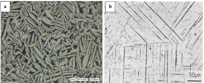
The microstructure of any material depends on its composition, processing steps, heat treatment and cooling rates (Wasz et al., 1996). When CP-Ti is heated to the β-Ti phase region and cooled down to α-Ti phase, usually the β-Ti phase is not retained but transforms back to its room temperature α-Ti phase due to low quantity of beta stabilising elements. This transformation can be of martensitic type or can occur by diffusion controlled nucleation and growth process depending on cooling rate and composition (Lütjering et al., 2007a). A martensitic microstructure (Figure 1.7) resulting from quenching is characterised by extremely fine acicular morphology which exhibits high strength and hardness but reduced ductility and toughness. Microstructure by diffusion controlled nucleation and growth is obtained by slower cooling rates producing a coarse Widmanstätten α plus α-prime or some retained β-phase (Figure 1.7). This microstructure has very low strength and hardness but the ductility and toughness is higher than the martensitic microstructure (Donachie, 2000).
28 Crystallographic orientation relationship between α and β is given by the Burgers relationship:
(110 )β || ( 0002 )α [111 ]β || [1120 ]α
According to this relationship, a BCC crystal can transform to 12 hexagonal variants, having different orientations with regard to the parent β crystal (Lütjering et al., 2007a).
Figure 1.7. Microstructure example of a) Widmanstatten in pure titanium and b) Martensitic in Ti6Al4V
1.1.3 Alloying elements effect on CP-Ti mechanical properties
Commercially pure titanium (CP-Ti) grades produced according to the ASTM standards have compositions as shown in Table 3 (Welsch et al., 1993). The concentration of carbon, nitrogen and hydrogen are typically very low and in order to compensate for the low strength oxygen is intentionally added to enhance the strength (Qian et al., 2015; Welsch et al., 1993). However, the addition of oxygen has to be controlled in order to minimise the reduction in fracture toughness and ductility. A summary of the influence of the alloying elements on the α to β transformation temperature , tensile strength and hardness is presented in Table 3 (Donachie, 2000; Welsch et al., 1993). The β-transus denotes the α to β phase transformation temperature during heating, while the α-transus is the β to α phase transformation during cooling. High purity titanium grades with lower interstitial content have low strength and
29 hardness, and the α to β phase transformation temperature is lower, as compared to those with higher interstitial content which stabilizes the alpha phase (Lütjering et al., 2003).
Table 3. ASTM standard grades of commercially pure titanium. Welsch et al. (1993).
Designation Impurity limits
(wt%) β-transus (°C) α-transus (°C) Vickers hardness (HV) Tensile strength (MPa) C H O Fe N ASTM grade 1 0.08 0.015 0.18 0.2 0.03 880 888 126 240 ASTM grade 2 0.08 0.015 0.25 0.3 0.04 890 913 210 340 ASTM grade 3 0.08 0.015 0.35 0.3 0.05 900 920 225 450 ASTM grade 4 0.08 0.015 0.40 0.5 0.05 905 950 265 550
1.1.4 Sintering methods
Powder metallurgy processes are more competitive than other fabrication methods like casting, stamping or machining, due to lower energy consumption, higher material utilisation and reduced numbers of processing steps thus reducing cost. The process allows fabrication of combination of material that would be conventionally difficult to fabricate such as those with higher melting points. Powder metallurgy is favourably method of choice because finer microstructures yielding superior properties can be obtained such as higher strength and wear resistance. Greater precision is obtained, eliminating most or all of the finish machining operations required for castings. It avoids casting defects such as blow holes, shrinkage and inclusions. Thus with powder metallurgy near net-shape components are directly produced from powders while simultaneously reducing material input and fabrication costs making it an attractive alternative for the production of most materials. However, powder metallurgy processes are economical only when production rates are higher, since the tooling cost is quite appreciable (Masikane, 2016; Upadhyaya, 1997).
There are several sintering techniques available these include spark plasma sintering (SPS), uniaxial hot-pressing (HP), hot isostatic pressing, (HIP) and pressing & sintering (P&S) (Bolzoni et al., 2013). In HP, a conventional sintering method, the powder is loaded into a graphite mold and sintered, under uniaxial applied pressure, by indirect heating via resistive heating units (Shon et al., 2014a). However, HP often requires very long time for sintering (several hours) and as a result high energy consumption. On the opposite, Spark Plasma
30 Sintering (SPS) allows rapid consolidation (several minutes) and controlled grain growth by the reduction of the sintering temperature and time (Chaim et al., 2008; Chaim et al., 2012; Munir et al., 2006). Here also the powder is loaded in a graphite mold and a uniaxial pressure is applied but the heating is directly obtained by the use of DC pulsed current passing through the material and/or the mold (Munir et al., 2006). The two methods are widely used by researchers, SPS technique is a promising technique due to aforementioned reasons (Yang et
al., 2015).
1.1.5 Sintering of titanium, densification and mechanical properties
Recent studies have shown that SPS technique can produce material with relatively improved properties. Ti6Al4V master alloy and TiAl intermetallic are among advanced materials that are widely used in high added value industries and thus most investigated by the economic SPS technique (Abedi et al., 2016; Crosby et al., 2014; Garbiec et al., 2016; Hussainova, 2003; Kus et al., 2016; Lampke et al., 2006; Manière et al., 2017; Martins et al., 2017; Matsugi et al., 1996; Mischler et al., 2014; Prakash et al., 2016; Trzaska et al., 2016; Weston
et al., 2015) while only few investigations are focused on SPS of commercial pure titanium.
Sintering of CP-Ti by SPS has been reported by Zadra et al. (2008), Weston et al. (2015), Shon et al. (2014b) and Shon et al. (2014a). In their studies, these authors have shown that sintered CP-Ti components produced have similar Vickers hardness values close to ASTM grades (126-265HV) (Welsch et al., 1993). Zadra et al. (2008) investigated the use of SPS on
45μm spherical CP-Ti grade 1 and irregular shaped CP-Ti grade 3. Sintering experiments were conducted in the temperature range 750 - 1100°C for 5min, under uniaxial pressure of 60MPa in vacuum followed by free cooling to produce SPS pellets with diameter and thickness of 30mm and 5mm respectively. Full densification for both grades was reached at 950°C but at 800°C the relative density was already 99%. However, the grain sizes of the two grades were different when sintered at 950°C. CP-Ti grade 1 grains were coarser (~30µm) compared to that of CP-Ti grade 3 (~16µm). These authors explained these differences by the amounts of dissolved oxygen which was measured on the sintered pellets and was relatively higher (~0.32wt%) in CP-Ti grade 3 compared to CP-Ti grade 1 (~0.075wt%). On the contrary, Weston et al. (2015) explained this phenomenon in terms of particles shapes. For spherical particles the grain growth was rapid because there were higher initial particle-to-particle contacts with smaller pores and thus underwent more densification. In contrary to areas with less particle interactions and larger pores as found in irregular shaped particles
31 leading to lower densification. However, it is known that, oxygen is very detrimental to the mechanical properties of CP-Ti and its alloys because it has an influence on the microstructure (Yan et al., 2014). ASTM CP-Ti grades are classified according to the oxygen content dissolved and this has shown to have effect on the transus temperature and Vickers hardness. For instance ASTM grade 1 has low oxygen content of 0.18wt% (~126HV) leading to lower transus temperature (890°C) while grade 3 has high oxygen content of 0.35wt% (~280HV) thus increasing the transus temperature to 920°C (Lütjering et al., 2007b; Welsch
et al., 1993). Zadra et al. (2008) found that Vickers hardness of CP-Ti grade 3 (~190-240HV) was higher than CP-Ti grade 1 (~120-150HV) whatever the sintering temperature. The difference in Vickers hardness was attributed to high amount (~0.3-0.34wt %) of oxygen dissolved in grade 3.
Eriksson et al. (2005), studied the influence of sintering pressure and temperature on the morphology of SPS partially consolidated CP-Ti powders. The compacts heated to 200°C and 500°C with 50MPa pressure did not present change in grain size and morphology but the latter sample at 600°C was ~90% dense. According to the authors, at 500°C, particles deformation features were observed at grain boundaries instead of micro-welding and local melting of particles. However, the authors seem not to discuss the effect of pressure on the sintering mechanisms occurring. Different sintering mechanisms influenced by compaction pressure have been reported for Ti6Al4V alloy during SPS (Garbiec et al., 2016) . The authors explained that sintering mechanisms at 5MPa compaction pressure occurred by electric discharges between particles and were dominant during the whole sintering stage. At much higher compaction pressure, at 25MPa and above, the electric discharges were only dominant in the early stages of sintering and were suppressed thereafter. The presence of spark discharges which is a pathway for electron migration have been proposed by Tokita (1999). This phenomenon occurs in the initial stages of sintering and leads to neck formations between particles. Experimentally neck formations have been observed for Ti6Al4V alloy with and without applied pressure (Kus, 2017). In contrast, Trzaska et al. (2016) have suggested no detection of the electric arcs, plasma or local overheating in TiAl intermetallic, but plastic deformation as the main densification mechanism.
Garbiec et al. (2016) further suggest that increased compaction pressure assisted in densification during heating by more rapid formation of necks favoring Joule effect which in turn enhanced diffusion and thereafter grain growth resulted. The grain sizes of samples
32 sintered with heating rate of 300°C/min increased from 15.49±3.81µm at 5MPa to 143.6±46.8µm at 25MPa. However at 50MPa the grain sizes reduced to 86.94±19.28 µm, authors explain that Joule effect was inferior at this pressure compared with 25MPa. The same effect was observed for 200°C/min and 400°C/min heating rates. Wang et al. (2017) report plastic deformation as densification mechanism in TiAl intermetallics prepared by SPS, the authors related the effect of pressure on density. At sintering temperature of 1150°C, by increasing pressure from 10MPa to 50MPa, the density gradually increased from 3.947g/cm3 to 3.967 g/cm3. The authors explained that higher sintering pressure led to more severe plastic deformation and it accelerated the mass transport between the particles which promoted densification. Plastic deformation of particles was confirmed by Trzaska et al. (2016), TEM thin foils were extracted in between necks of sintered TiAl powder particles, high densities of dislocations and twins which are characteristics of plastic deformation were observed. Despite the reported studies on the densification and mechanisms governed by sintering pressure for Ti6Al4V alloy and TiAl intermetallic, there is however limited literature on pressure effect on densification of CP-Ti powders.
1.2. Metal Matrix Composites
Generally, metal matrix composites (MMCs) can be defined as materials consisting of at least two distinct phases with different chemical and physical properties, for example a ceramic reinforcement embedded in a metallic matrix (Chawla et al., 2006; Kainer, 2006). Metallic matrix is a continuous phase which is ductile, chemically unstable and has good thermal conductivity and its properties are improvised when reinforcement is introduced. Metallic matrix which have been explored in the literature include Al, Mg, Ti, Co, Ni, Be and Ag (Jayalakshmi et al., 2015; Kainer, 2006).
Ceramic reinforcement is a load bearing phase in the composite due to its high Young’s modulus, high strength and high stiffness (Jayalakshmi et al., 2015; Kainer, 2006). The morphology of ceramic phase may be long fibers, short fibers or particulates made of oxides, carbides, nitrides and borides (Jayalakshmi et al., 2015). The ceramic phases include SiC, Al2O3, B4C, TiB2, TiB, TiC, TiN, TiCN and graphite (Choi et al., 2013; Kelly et al., 2000; Song et al., 2013).
The selection of metal matrix and reinforcing ceramic phase entirely depend on foremost compatibility of the two phases, required properties, intended applications and cost efficiency (Nalwa, 1999). In this regard, when good compatibility is obtained between the two distinct
33 phases, the resultant MMCs have outstanding properties such as increased yield and tensile strength at room and elevated temperatures, increased young modulus of elasticity, improved corrosion and wear resistance over the individual phases and some conventional material (Balaji et al., 2015; Chawla et al., 2006; Choi et al., 2013; Kim et al., 2011).
MMCs are categorized according to the type of reinforcement morphology and there are three major groups namely; continuous reinforcement in the form of long fibers and discontinuous reinforcement in the form of short fibers or whiskers, and particulates as shown in Figure 1.8 (Clyne et al., 1995). Subsequently, the selection of reinforcement morphology is determined by the required properties, the application and the fabrication cost (Clyne et al., 1995; Kelly et
al., 2000). For instance, the continuously reinforced MMCs have anisotropic properties, thus
properties are high in the direction of the fiber orientation and the fabrication cost is relatively high (González et al., 2001). As a result, the discontinuously reinforced MMCs which have isotropic properties are favorable because they are easy to fabricate and fabrication cost is low (Batraev et al., 2014; Kim et al., 2011).
MMCs can be fabricated by several methods, the commonly used are listed here a) Liquid processes: casting, pressure infiltration, spray co-deposition and in-situ
b) Solid processes: powder metallurgy, extrusion, forging, pressing and sintering, roll bonding and co-extrusion, diffusion bonding
c) Gaseous state: physical vapor deposition (Chawla et al., 2006)
MMCs are mostly used in industrial application such as aerospace, automotive, structural, military, commercial, industrial products, electronic packaging and thermal management. (Rosso, 2006).The demand for the use of MMCs is attributed to the availability of the ever-evolving sources of relatively inexpensive reinforcements, and the frequent development of the processing routes which results in reproducible microstructures and properties (Ajayan et
34 Figure 1.8. Three classes of reinforcement’s morphology. Clyne et al. (1995)
1.2.1 Titanium Matrix Composites (TMC)
1.2.1.1 Continuously reinforced TMCs
SiC (SCS-6) fiber is the commonly used continuous reinforcing phase in TMCs normally with a larger diameter of about 100-140µm (Jayalakshmi et al., 2015). SiC fibers are strong, stiff, have low density, have anisotropic properties and are widely used for high temperature (815°C) applications (Campbell, 2010). Main application for these classes of materials is in hot structures (hypersonic airframe structures) and in jet engines replacing some portions of super alloys. However due to their high cost, the fabrication process and assembly their use is limited (Campbell, 2010; González et al., 2001). Moreover, interfacial reactions between titanium matrix and the fiber may occur during fabrication and also in later application at higher temperatures (Campbell, 2010; Gundel et al., 1991; Huang et al., 2015). As a result second phase particles (Ti3SiC2, TiCx and Ti5Si3(C)) formed at the interface cause defects and significantly decrease mechanical properties of these composite (Kieschke et al., 1991). Fukushima et al. (2000) studied the reaction kinetics between Ti15Al3V and SiC fiber at heat treatment temperatures of 1153K and additional heat treatment at 1203K and 1253K. The reaction zone thickness increased linearly with the square root of the heat treatment time. The interfacial tensile strength of the composites decreased with the increase of reaction zone thickness. Therefore, focus has been made on selecting a compatible reinforcement with titanium matrix and also various SiC fiber coatings such as Mo, B4C and C have been investigated to minimize or prevent the interfacial reactions (Luo et al., 2012; Zhang et al., 2014).
Continuous Discontinuous
35
1.2.1.2 Discontinuously reinforced TMCs
TMCs reinforced with discontinuous fibers, whiskers or particles have isotropic properties and allow easy fabrication of near net shaped components and also secondary processing of the composites is possible (Campbell, 2010). A wide variety of discontinuous reinforcements including SiC, TiC, TiB2, B4C, TiN, and TiCN have received great attention because of their ability to improve mechanical properties of titanium (Choi et al., 1994).These types of reinforcements are used in applications where the higher stiffness and strength properties of continuous reinforcements are not needed (Campbell, 2010).
Discontinuously reinforced TMCs (DTMCs) can be fabricated ex-situ and in-situ. For ex-situ fabrication (conventional processing), the reinforcing phase is prepared separately and later added to the metal matrix (Ajayan et al., 2006; Casati et al., 2014). Although DTMCs fabricated by ex-situ have demonstrated good properties making them suitable for variety of applications (Chen et al., 2014; Prasad et al., 2004), the composites interfacial bonding with the matrix is poor and sometimes the interface can be contaminated with second phases (Ajayan et al., 2006). In case of the in-situ composites, the desired reinforcements are synthesized during fabrication step with exothermic chemical reactions between a compound and the titanium matrix (Campbell, 2010). The interface between titanium and reinforcing phase is normally without an interphase and a strong interfacial bond exists. Microstructure is characterized by a uniform dispersion of reinforcing phases in the matrix yielding optimized mechanical properties (Kainer, 2006). Due to different growth kinetics occurring with the individual reinforcing fibers, whiskers or particles, there is no specified orientation and also their sizes vary.
Among reinforcements, TiC and TiB2 have shown to promote good wetting at the matrix/reinforcement interface, also they have showed to improve mechanical properties of Ti (Kim et al., 2011). However due to their high melting temperatures (Table 4) and thus low diffusivity, TMC made of both pure TiC and TiB2 phases are difficult to synthesize. However, the chemical instability of B4C when reacted with Ti tends to be favorable as the products formed are TiC, TiB2 and TiB. As a result simultaneous synthesis and consolidation of the TMCs by in situ method is accomplished. In the present study B4C is chosen as a constituent element for in situ synthesis and consolidation of Ti - (TiB2 + TiB + TiC) composites.
36 Table 4. Material properties of Ti, TiB2 TiB, TiC (Chandran et al., 2004) and B4C (Domnich et al., 2011; Sairam et al., 2014)
Property Ti TiB2 TiB TiC B4C
Density (g/cm3) 4.57 4.52 4.56 4.92 2.52
Elastic modulus (GPa) 110 540 371 450 570
Vickers hardness ( HV) 150 2200 1800 3200 3793
Melting temperature (°C) 1668 2970 2200 3054 2763
1.2.1.3 Ti-TiB
2composite
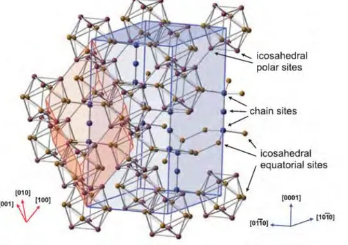
Titanium diboride (TiB2) is a ceramic material known to have relatively high strength, durability and density of 4.52g/cm3 close to that of pure titanium. It is characterized by high melting point of 2970°C, hardness of 2200HV, elastic modulus of 540GPa, strength to density ratio and excellent wear resistance (Ravi Chandran et al., 2004). This material is used in engineering applications such as impact resistant armor, cutting tools, molten metal crucibles and heavy duty wear application (Basu et al., 2006; Vallauri et al., 2008). Its high melting point has restricted its broader application due economic factors. But with the current favorable developments in fabrication of components by powder metallurgy techniques, its production and thus vast application becomes possible (Munro, 2000). TiB2 has unit cell consisting of eight Ti atoms at the vertices and two boron atoms at the center. The crystal structure of TiB2 is shown in Figure 1.9, is a layered hexagonal structure with alternating closed-packed hexagonal layers of titanium and graphite-like boron layers. Similar to TiC and other ceramics, it has relatively low fracture toughness (~5MPam½) and low self-diffusion coefficient making it difficult to sinter, thus a metallic binder is often needed in sintering (Morsi et al., 2007).
37 Figure 1.9. TiB2 crystal structure (Will, 2004)
In the production of Ti-TiB2 composites, the Ti + 2B → TiB2, reaction has more negative Gibbs free energy (∆G). However, when mass fraction of Ti is higher than TiB2, TiB2 can further react with Ti to form TiB phase by this reaction, Ti + TiB2 → 2TiB (Chandran et al., 2004). The reaction has a slightly negative ∆G value (Figure 1.10) assuring that it can occur in Ti-TiB2 composites. Moreover, because of low diffusion rates of B in Ti, the reaction rate is limited, so TiB2 phase initially forms (from first reaction) and then followed by TiB phase (Morsi et al., 2007).Eriksson et al. (2008) investigated densification and deformation of Tix (TiB2)1-x composites by SPS from 1400 up to 1900°Cat holding times from 0 to 3min and pressure of 50MPa, using coarse grained Ti (45µm) and amorphous TiB2 (1.4µm). Authors studied the effect of varying mass fraction (x=0.05, 0.1 & 0.2) of Ti on densification and phases formed. They found that at 1500°C, 3min and 50MPa densification was 100% for mass fraction x=0.05 and 0.1 when increased to x=0.2 the relative density decreased to 97%. Phases present for the three compositions after sintering was TiB2 with Ti but for composite with x=0.2 TiB phase in minor amount was also detected.
HCP : P6/mmm space group Lattice parameters: a = 0.3026nm c = 0.3226nm
38 Figure 1.10. The values of ∆G for some reactions forming TiC, TiB2 and TiB as a function of
temperature (Mao et al., 2015)
1.2.1.4 Ti-TiB composites
Titanium monoboride, TiB, can be synthesized from a reaction between titanium and powder sources such as TiB2, pure B, CrB and MoB (Balaji et al., 2014; Feng et al., 2006). Various synthesizing techniques such as combustion synthesis, rapid solidification and powder metallurgy have been employed to synthesize Ti-TiB composites (Cao et al., 2015; Feng et
al., 2006). In cases whereby the powder source is TiB2, TiB whisker is normally an intermediate phase between Ti and TiB2 when incomplete reaction occurs. TiB has excellent chemical stability and the interfacial bonding between Ti and TiB is clean without interphase and this has shown to result in improved mechanical properties (Feng et al., 2006). TiB has density of 4.56g/cm3, high hardness of 1800HV, elastic modulus of 371GPa modulus thermal expansion coefficient of 8.6x10⁻⁶, thermal conductivity of 7.2 x 10⁻⁶K-¹. Its similar density to Ti make TiB even more attractive reinforcement because there is less modification in density, while mechanical properties of Ti are improved (Cao et al., 2015; Ravi Chandran et al., 2004; Sahay et al., 1999).
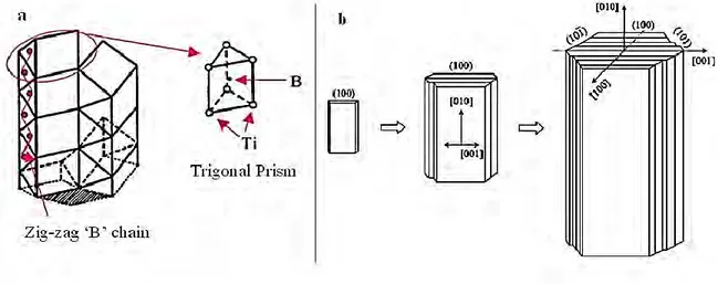
In the crystal structure of TiB the principal building block is trigonal prism, whereby six Ti atoms are positioned at the corners and the B atom is at the center. The trigonal prisms stack up transversely in columnar arrays forming orthorhombic unit cell in its stable form of B27 structure (FeB type). From this, the B atoms arrangement pattern is characterised by zigzag chains which are parallel to the [010] direction as shown in Figure 1.11(a) (Feng et al., 2006; Panda et al., 2006; Ravi Chandran et al., 2004). The growth mechanism of the TiB is the
39 stacking up of the (100) plane and the cross section of the TiB is normally a hexagonal structure with (100), (101) and (101̅) planes as show in Figure 1.11(b). Moreover the growth rate of the transverse direction is slower than the longitudinal direction (Feng et al., 2006; Ravi Chandran et al., 2004). Therefore, morphology of TiB is normally characterised by a needle like structure, namely whiskers (Feng et al., 2006).
Figure 1.11. Crystal structure of TiB: a) Stacking up trigonal prisms with B zigzag chain (Panda et al., 2006), b) TiB whisker growth (Feng et al., 2006).
Shen et al. (2011), in situ synthesized TiB reinforced TMCs from Ti and TiB2 powders with average particles sizes of 30 μm and 4.5μm fabricated by SPS method respectively, with a composition of 15wt% TiB2 and 85wt% Ti powder. The structure of the sintered composites showed that TiB was formed at 950°C and the microstructure revealed a uniform distribution of needle and rod shape TiB whiskers with a high aspect ratio growing rapidly with sintering temperature. The rapid growth of the TiB whiskers leads to coarsening and agglomeration of the whiskers leading to cross-sectional diameters from 0.2μm to 2 μm at 950°C and 1150°C respectively. According to the authors the TiB whiskers which are fine grow along the grain boundaries while others grow towards inner grains of titanium. Sahay et al. (1999) reported three different morphology of TiB formed at low and high volume fraction of the reinforcement fabricated by hot pressing. The first morphology at low volume fractions of 0.3 was characterised by long and needle-shaped TiB whiskers which are isolated and randomly oriented in the Ti matrix. The second morphology at volume fractions of 0.55 to 0.86, colonies of refined and densely packed short TiB whiskers which seemed to be interconnected
Orthorhombic: 62(Pnma) space group
Lattice parameters: a = 0.612nm, b = 0.306nm, c = 0.456nm
40 were observed. Chandran et al. (2004) explain the interconnection morphology of TiB whiskers to be due to spatial diffusion limitations of boron atoms from the parent TiB2 particle and resulted in interceptions between TiB whiskers forming from that parent TiB2. The third morphology at the highest volume fractions of 0.92, the TiB whiskers were coarse and elongated with a few needle-shaped whiskers. Further illustration of the different morphologies developments at low and high volume fraction of starting TiB2 powders is shown in Figure 1.12. The dominant reinforcing phase was TiB however at higher volume fractions of 0.86 and 0.92, a significant amount of unreacted TiB2 was still present (Sahay et al., 1999). Table 5 presents some of the relative densities and hardness values of sintered
Ti-TiB composites found in literature.
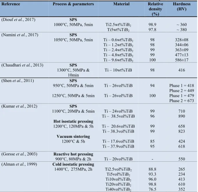
Table 5. Relative densities and hardness values of Ti-TiB2/TiB sintered composites
Reference Process & parameters Material Relative
density (%)
Hardness (HV)
(Diouf et al., 2017) SPS
1000°C, 50MPa, 5min Ti2.5wt%TiB2
Ti5wt%TiB2
98.9
97.8 ~ 360 ~ 380
(Namini et al., 2017) SPS
1050°C, 50MPa, 5min Ti – 0.6wt%TiB2
Ti – 1.2wt%TiB2 Ti – 2.4wt%TiB2 Ti – 4.8wt%TiB2 Ti – 9.6wt%TiB2 98 98 99 99 100 328±08 344±06 363±09 477±13 586±17 (Chaudhari et al., 2013) SPS 1300°C, 50MPa & 10min Ti – 10wt%TiB 98 416 (Shen et al., 2011) SPS
950°C, 50MPa & 5min 1250°C, 50MPa & 5min
Ti – 26vol%TiB Ti – 26vol%TiB 94 100 Phase 1 = 418 Phase 2 = 449 Phase 1 = 479 Phase 2 = 673 (Kumar et al., 2012) SPS
1100°C, 20MPa & 5min
Hot isostatic pressing
1200°C, 120MPa & 5h Vacuum sintering 1200°C & 5h Ti – 24vol%TiB Ti – 38.5vol%TiB Ti – 20.6vol%TiB Ti – 38.3vol%TiB Ti – 17.6vol%TiB Ti – 37.9vol%TiB 99 96 99 99 85 95 710 890 658 823 424 618
(Gorsse et al., 2003) Reactive hot pressing
900°C, 80MPa & 2h Ti – 20vol%TiB - 550
(Alman et al., 1999) Cold isostatic pressing
1400°C, 275MPa, 2h Ti2.5vol%TiB2 Ti5vol%TiB2 Ti10vol%TiB2 Ti20vol%TiB2 Ti40vol%TiB2 88.8 93.3 96.0 98.8 76.5 265 234 413 610 352
41 Figure 1.12. Schematics of TiB whisker morphologies development in Ti-TiB composites at
starting volume fraction of TiB2: (a, b & c) low volume fraction of 10vol% TiB2, (d, e & f) high volume fraction of 29vol% TiB2 (Sahay et al., 1999).
1.2.1.5 Ti-TiC composites
Titanium carbide (TiC) belongs to a class of interstitial carbides and its crystal structure is face centered cubic (FCC) (Fu et al, 2017). The building unit cell consists of six titanium atoms positioned in the corners and surface centers of the FCC with interstitial carbon atom positioned in center of each corners and the cubic as shown in Figure 1.13 (Jin et al., 2002; Nie et al., 2012). Two types of bond exist in TiC that is metallic Ti-Ti bond and a much stronger covalent Ti-C bond (Djellouli et al., 2001; Johansson, 1995). TiC has high electrical and thermal conductivity of 30 x 106 S/m and 28.9 Wm-1K-1 respectively. It has low density of 4.92g/cm3, high hardness greater than 3200HV, elastic modulus of 450GPa, low friction coefficient, high solvency with other carbides and high melting temperature of 3054°C due to its strong covalent bonds (Fu et al., 2017; Ravi Chandran et al., 2004). These properties make TiC an abrasive material that is resistant to high temperature oxidation and in chemically corrosive environments (Vallauri et al., 2008). It is widely used in abrasive wear applications
42 such as cutting tools, gears, bearings and shafts it is also useful in erosion, corrosion and creep (engine) applications (Covino Jr et al., 2002; Gu et al., 2012; Mohanty et al., 1995)
Figure 1.13. TiC crystal structure (Nie et al., 2012)
TiC is brittle in nature, as such metallic binders are normally incorporated to provide ductility and toughness in the bulk material. In terms of sintering, the binder phase also aid in consolidation to full density by controlling bonding with the ceramic phase (Hussainova, 2003). This is due to TiC poor sinterability resulting from its low self-diffusion coefficient which is unfavorable for mass transfer. At high temperature it experiences rapid grain growth leading to pores entrapment in grains and also oxide impurity in the powder inhibits densification (Gu et al., 2017). However, with addition of binding phase to TiC the hardness and corrosion/oxidation resistance properties are reduced. Nevertheless, economical sintering of TiC still partly requires liquid phase for full densification during sintering because of its higher melting temperature (Teber et al., 2012). Previous studies have shown that high sintering temperature was required for TiC consolidation as shown in Table 6. Relative densities obtained by presureless sintering in Fu et al. (2017) and Gu et al. (2017) at temperatures of 1700°C and 2300°C was 95.7% and 96.67% with grain sizes of 5.5±0.9µm and 7.5µm respectively. For hot pressing and spark plasma sintering in the study of Xue et al. (2016) and Cheng et al. (2012) at 2000°C and 1600°C densification was 98.15% and 99% with grain sizes of 19.62µm and 3.21µm respectively. These results clearly indicate the need for a binding phase to lower the sintering temperature while achieving full densification. Several metallic binding phases such as Co, Cr, Ni, Mo, Al, Ti and Fe have been explored and have shown excellent hardness, fracture toughness and wear resistance (Degnan et al., 2002; Fu et al., 2016; Kübarsepp et al., 2001; Lagos et al., 2016; Li et al., 2009; Teber et al.,
FCC: Fm-3m space group
43 2012; Wu et al., 2011). TiC composites based on Ti and Ti6Al4V as matrix are the most common combination explored mainly because of their chemical compatibility (Georgiou et
al., 2017; Konitzer et al., 1989; Lagos et al., 2016).
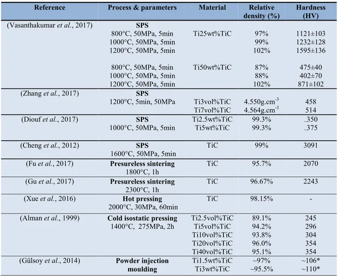
Table 6. Relative densities and hardness values of Ti-TiC sintered composites
*HRB
According to the binary phase diagram of Ti-C in Figure 1.5, the interaction between Ti based matrix and TiC leads to formation of wide range of (x=0.5-1.0) sub-stoichiometric carbides according to reaction 1 (Baker, 1992).
(1-x)TiC + xTi = TiC1-x [Eq.1] Quinn et al. (1984) investigated solid state reaction of single-crystal diffusion couples of Ti and TiC forming sub-stoichiometric carbides during sintering and hot pressing from 1350 up
Reference Process & parameters Material Relative
density (%) Hardness (HV) (Vasanthakumar et al., 2017) SPS 800°C, 50MPa, 5min 1000°C, 50MPa, 5min 1200°C, 50MPa, 5min 800°C, 50MPa, 5min 1000°C, 50MPa, 5min 1200°C, 50MPa, 5min Ti25wt%TiC Ti50wt%TiC 97% 99% 102% 87% 88% 102% 1121±103 1232±128 1595±136 475±40 402±70 871±102 (Zhang et al., 2017) SPS
1200°C, 5min, 50MPa Ti3vol%TiC
Ti7vol%TiC 4.550g.cm
-3
4.564g.cm-3 458 514
(Diouf et al., 2017) SPS
1000°C, 50MPa, 5min Ti2.5wt%TiC Ti5wt%TiC 99.3% 99.3% ~~350 375
(Cheng et al., 2012) SPS
1600°C, 50MPa, 5min TiC 99% 3091
(Fu et al., 2017) Presureless sintering
1800°C, 1h TiC 95.7% 2070
(Gu et al., 2017) Presureless sintering
2300°C, 1h TiC 96.67% 2243
(Xue et al., 2016) Hot pressing
2000°C, 30MPa, 60min TiC 98.15% -
(Alman et al., 1999) Cold isostatic pressing
1400°C, 275MPa, 2h Ti2.5vol%TiC Ti5vol%TiC
Ti10vol%TiC Ti20vol%TiC Ti40vol%TiC 89.1% 94.2% 93.8% 96.0% 95.1% 245 296 304 354 354
(Gülsoy et al., 2014) Powder injection
44 to 1525°C. According to the authors, the reaction between reactants proceeds by carbon diffusion at the interface of reactants forming sub-stoichiometric carbides in the sequence TiC0.89, TiC0.53 and TiC0.01 from the centre of TiC particle into the Ti matrix.. Microstructural analysis of reaction couple revealed growth of second phase platelets into the original TiC crystal. The morphology of the platelets resembled that of Widmanstatten pattern. Authors suggest that carbon diffuse across the Ti-TiC interface and react to form TiC0.5, the product nucleates at the interface and grow with the advancing phase boundary and also back into the original carbide crystal. The Ti2C phase provides a faster diffusion path for carbon atoms in new carbide phase (Ti2C) and also in the original carbide crystal.
Wanjara et al. (2000) also reported the presence Ti2C phase at interface of Ti6Al4V alloy and TiC compacts processed by graphite-element vacuum furnace at 1200 and 1500°C. Microstructural analysis by low voltage FEG-SEM showed a distinct phase at the boundary of TiC particles. EDS quantitative elemental analysis revealed a low amount of carbon at boundary and it increased towards the center of the TiC particle. Further analysis by neutron diffraction revealed that lattice parameters of the matrix increased with the holding time at the various isothermal temperatures, suggesting that carbon diffuse from the TiC to the Ti6Al4V alloy matrix. However, the authors do not report any Widmanstatten pattern morphology for Ti2C in the TiC particles as observed by Quinn 1984. They reported a rapid growth of interface layer with processing temperature at 1500°C until the entire TiC particle has fully reacted. However, with in-situ synthesized Ti based TiC composites using various carbon sources such as graphite (Yu et al., 2017), carbon fiber (Hao et al., 2015), graphene (Zhang et al., 2017), the interface between matrix and reinforcing phase is normally clean without
interphase and have strong metallurgical bonds (Kainer, 2006). On the contrary, Vasanthakumar et al. (2017) reported formation of non-stoichiometric TiCx when CNT was the carbon source. In fact, the carbon addition was obtained from decomposition of toluene during milling for 10h this was confirmed with XRD and Raman spectroscopy analysis and not from the CNT.
1.2.1.6 Ti - B
4C composites
Boron carbide (B4C), is one of the hardest engineering materials with hardness value of 3793HV, a high elastic modulus of 570GPa, low density of 2.52 g/cm3, melting temperature of 2763°C and high electrical resistivity at elevated temperatures (Domnich et al., 2011; Sairam et al., 2014). Because of its high melting point and thermal stability it is used in