Official URL : http://cit.kuleuven.be/aceme13/
This is an author-deposited version published in: http://oatao.univ-toulouse.fr/ Eprints ID: 9055
To cite this version: Bodénan, Françoise and Bourgeois, Florent and Petiot,
Charlotte and Augé, Thierry and Bonfils, Benjamin and Julcour-Lebigue, Carine and Guyot, François and Boukary, Aissa and Tremosa, Joachim and Lassin, Arnault and Chiquet, Pierre Ex-situ mineral carbonation: resources, process and environmental assessment (Carmex project). (2013) In: 4th International Conference on Accelerated Carbonation for Environmental and Materials Engineering, 10-12 Apr 2013, Leuven, Belgium.
O
pen
A
rchive
T
oulouse
A
rchive
O
uverte (
OATAO
)
OATAO is an open access repository that collects the work of Toulouse researchers and makes it freely available over the web where possible.
Ex-situ mineral carbonation: resources, process and
environmental assessment (Carmex project)
F. Bodénan
1*, F. Bourgeois
2, C. Petiot
3, T. Augé
1, B. Bonfils
2, C. Julcour
2,
F. Guyot
4, A. Boukary
3, J. Tremosa
1, A. Lassin
1, P. Chiquet
51 BRGM, Orléans, France
2 Université de Toulouse, Laboratoire de Génie Chimique (LGC), Toulouse, France 3 Bio-IS, Paris, France
4
IPGP, Paris, France
5
TOTAL, Pau, France
*Corresponding author: [email protected]
Abstract
This article presents the main results of the Carmex project (2009-2012), whose purpose was to review the feasibility of ex-situ mineral carbonation in terms of resource availability, performance of the aqueous mineral carbonation process and life cycle analysis criteria. This collaborative project looked at a wide range of generic issues about this CO2 mitigation option, with particular views on assessing its potential
in the context of New-Caledonia. Indeed, insularity and local abundance of 'carbonatable' rocks and industrial wastes (i.e. rich in MgO, CaO, if not Fe(II)O), coupled with significant GHG emissions from first-class nickel pyrometallurgical industries, make it a potential candidate for application of ex-situ mineral carbonation. The project conducted a worldwide analysis of the potential of ex-situ mineral carbonation using a dedicated SIG-based tool. Using a variety of materials the project also reviewed a number of critical issues associated with the aqueous mineral carbonatation process itself, with promising perspectives. Finally, through life cycle analysis of the system as a whole, ex-situ mineral carbonation was compared to mainstream CSC solutions. It was concluded that the viability of this CO2 storage option
is located at the level of the process itself and lies with the optimisation of its operating conditions.
© 2013 The Authors.
Introduction
Mineral carbonation, which involves trapping CO2 by chemical reaction with
carbonable mineral phases to form stable inert carbonates, can be considered as an alternative solution to geological CO2 storage, which is at present the main, if not only,
the solution for storing industrial CO2 emissions on a large scale. With aqueous mineral
carbonation, two distinct reactions occur: first the 'carbonatable' cations Mg2+ (Ca2+, Fe2+) are leached out of the ore, and then they precipitate with dissolved CO2 to form
carbonates. The overall reaction is typically written as Mg2SiO4 + CO2 + 2H2O ->
2MgCO3 + H4SiO4. Depending on the conditions, serpentinization-like reaction can also
This article presents the main results of the French Carmex project (2009-2012), whose purpose was to review the industrial feasibility of ex-situ mineral carbonation, essentially in terms of resource availability, performance of the aqueous mineral carbonation process and life cycle analysis criteria.
Worldwide potential for ex-situ mineral carbonation - Geographical
Information System (GIS)
World data on (i) CO2-emission sites and (ii) ore deposits in mafic/ultramafic (M/UM)
rock contexts have been cross-examined through a GIS (under ArcGIS) in order to identify sites of potential interest for implementing the ex-situ carbonation method on a worldwide scale. Applying criteria about the nature and quantity of mining wastes, volumes of CO2 emissions, distance between mine and emission sites, and adding
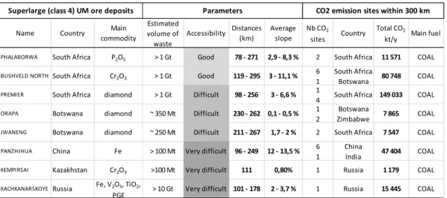
mining data from the literature, has led to a first selection of eight ‘super large’ potential ore deposits in an ultramafic rock context, all within a 300 km radius of coal-fired industrial plants emitting over 1Mt/year CO2. These sites are located in Botswana,
South Africa, China, Russia and Kazakhstan1. Additional information is reported in Table 1 that indicates the level of accessibility of the sites (good/difficult/very difficult), considering the mining value of the residues – i.e. possible profitable recycling of rare metals- the total length of pipelines to transport the CO2 from the emission sites, local
topography – calculation of average slope parameter which results in evident access difficulties.
Table 1. First selection of 8 superlarge sites
Name Country Main commodity Estimated volume of waste Accessibility Distances (km) Average slope Nb CO2 sites Country Total CO2
kt/y Main fuel
PHALABORWA South Africa P2O5 > 1 Gt Good 78 - 271 2,9 - 8,3 % 2 South Africa 11 571 COAL BUSHVELD NORTHSouth Africa Cr2O3 > 1 Gt Good 119 - 295 3 - 11,1 %
6 1
South Africa
Botswana 80 748 COAL
PREMIER South Africa diamond > 1 Gt Difficult 98 - 256 3 - 6,6 % 1
4 South Africa 149 033 COAL
ORAPA Botswana diamond ~ 350 Mt Difficult 230 - 262 0,1 - 0,5 % 1
2
Botswana
Zimbabwe 7 865 COAL
JWANENG Botswana diamond ~ 250 Mt Difficult 211 - 267 1,7 - 2 % 2 South Africa 7 547 COAL
PANZHIHUA China Fe > 100 Mt Very difficult 96 - 249 12 - 13,5 % 6
1
China
India 47 404 COAL
KEMPIRSAI Kazakhstan Cr2O3 >100 Mt Very difficult 111 0,80% 1 Russia 1 179 COAL KACHKANARSKOYE Russia Fe, V2O5, TiO2,
PGE > 10 Gt Very difficult 101 - 178 2 - 3,7 % 1 Russia 15 445 COAL
Superlarge (class 4) UM ore deposits Parameters CO2 emission sites within 300 km
The criteria used above are rather drastic, hence the small number of sites that this analysis identified as early opportunities for ex-situ mineral carbonation. But this example was intended as a demonstration of the value of using modern SIG-based technology for decision-making about the value of implementing mineral carbonation around the globe. Indeed, other criteria can be used which would yield different potential sites, for example using shorter transport distances, using ultramafic and mafic resources instead of mining wastes, etc. It could also be further improved by
applying hydrographical, chemical and mineralogical and economic criteria. The outcomes of this analysis can be compared locally with the corresponding geological storage potential evaluation, which can be very interesting.
Materials and methods
Samples: chemical content and mineralogy
Figure 1. Ternary diagram showing the mineral proportion of the three types of rocks tested:
harzburgite (Hz), lherzolite (Lz) and wehrlite (We) in modal fraction of olivine, orthopyroxene and clinopyroxene. The grey zone corresponds to rocks commonly found in ophiolite and
ultramafic complexes.
Three types of material were tested: natural peridotites (harzburgite Hz1, Hz2 and wehrlite We1 collected in New Caledonia and lherzolite Lz1 from the French type locality – the proportion of each mineral in the three rock types without considering serpentine is given in Figure 1). Pure synthetic olivine from Magnolithe GmbH obtained after 1600°C calcination of natural serpentinite and Ni slag form SLN Doniambo pyrometalurgy plant in Nouméa were also studied.
Global chemical analyses expressed as oxides show that the selected rocks are rich in MgO and contain some CaO (Table 2). As confirmed by volumetric analysis, slags also contains potentially carbonable Fe(II)O. Like most peridotite in New Caledonia, Hz1 and Hz2 contain about 88 % serpentine (lizardite - LOI 9.1-10.4%) and 10 % olivine [average structural formulae (Mg1.83,Fe0.07)SiO4] and rare occurrence of Mg, Fe
pyroxenes –enstatite type. Wehrlite and lherzolite are also composed of serpentinized olivine but to a lesser extent (LOI 5.6-6.2 %). They also contain Ca, Mg, Fe pyroxenes – diopside and augite type. Olivine Magnolithe composition varies between (Mg1.88Fe0.12)SiO4 and (Mg1.82,Fe0.18)SiO4. Slags are composed of olivine/forsterite and
an amorphous phase referred to described as glass hereafter. Quench dentritic olivine and larger euhedral olivine (Mg1.90,Fe0.1)SiO4 represent about 30 % of the slag but their
effect on the slag composition is low, its whole composition being close to its point (EPMA) composition (MgO 33.19%, CaO 0.2%).
Table 2. Chemical content of the samples (X-ray fluorescence after akaline fusion)
Hz1 Hz2 We1 Lz1 Olivine/ Magnolithe slag MgO 41.1 40.4 32 30.8 47.35 31.9 CaO 0.6 0.9 4.9 5.0 0.17 0.2 Fe2O3t 7.8 7.3 7.5 7.6 9.79 12.0 (FeII) LOI (1000°C) 9.12 10.36 6.17 5.67 0.00 <0.1 Total (majors) 99.3 99.7 99.0 99.52 99.57 99.85 Total C (initial) 0.1 0.1 <0.1 0.12 0.04 0.13 Experimental set-up
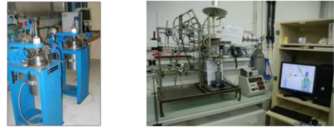
Two distinct test rigs (Figure 2) were used during this work, which differ in volume and range of possible operating conditions.
Figure 2. Experimental set-up used in CARMEX project: set-up1 (left) and set-up2 (right) Set-up 1: the equipment is composed of a 2L stirred autoclave reactor with a Teflon inner jacket equipped with a magnetic stirrer that can maintain a rotating speed as high as 1500 rpm, is rated up to 200 bars and 343 °C. Starting with a standard liquid CO2 bottle (with pressure around 50 bars), the CO2 is compressed via a mechanical
pressure booster to 200 bars. The whole compression system is assembled inside a dedicated closet that is kept at a temperature about 45°C, so that CO2 remains
supercritical in the system that feeds the autoclave. The control panel controls the operating total pressure inside the autoclave chamber via an electromagnetic CO2
injection valve and the temperature via a heating coil.
Set-up 2: The experimental set-up comprises a 300 mL stirred autoclave reactor with a glass inner jacket and Hastelloy internals. The CO2 pressure inside the reactor is
regulated using a CO2 ballast tank, and instantaneous CO2 consumption by the
ballast. The slurry is stirred by a gas inducing stirrer that achieves high gas-liquid mass transfer. Slurry temperature is monitored and PID controlled.
Water analyses and solid characterization
Throughout this project, it was found over and over that understanding of process performance required systematic and comprehensive analysis of both liquid and solid phases. Such analytical work is time and energy intensive, but investigation of one phase only, the liquid phase being simplest, is insufficient for sound analysis of aqueous mineral carbonation systems.
Set-up 1: after filtration at 0.2µm, pH and alkalinity was measured. Major anions and cations were analysed by ICP-AES and IC. Solid were dried and total inorganic carbon was measured. Powder and polished thin sections were observed on SEM coupled with elemental analysis (EDX). X-Ray diffraction was also performed. Set-up 2: after filtration using a 0.2 µm micropore filter liquid phase was analysed by ICP-AES to determine the amount of dissolved minerals (Mg, Fe, Si). Solid phase was characterized by different techniques: thermogravimetry coupled with IR detection of released gases to confirm the amount of carbonates, electronic microscopy (SEM and TEM) coupled with elemental analysis (EDX) to identify the different mineral phases, and laser diffraction particle size analysis.
The extent of carbonation (or initial Mg converted) is defined as the fraction of Mg from the initial solid that is extracted and forms MgCO3.
Process development
Direct aqueous carbonation tests were performed with the equipment described above. Studies focused mainly on increasing the reactive surface through grinding, limiting the conditions for the formation of a passivation layer, thermally activating the serpentine (derived from the alteration of olivine), using organic or inorganic additives (including seawater) and studying the reaction kinetics.
Direct aqueous carbonation of rocks and slags
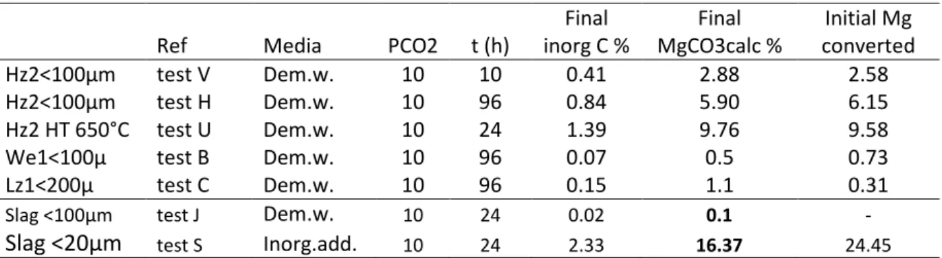
Table 3. Selective carbonation tests on rocks and slags
Ref Media PCO2 t (h)
Final inorg C % Final MgCO3calc % Initial Mg converted Hz2<100µm test V Dem.w. 10 10 0.41 2.88 2.58 Hz2<100µm test H Dem.w. 10 96 0.84 5.90 6.15 Hz2 HT 650°C test U Dem.w. 10 24 1.39 9.76 9.58
We1<100µ test B Dem.w. 10 96 0.07 0.5 0.73
Lz1<200µ test C Dem.w. 10 96 0.15 1.1 0.31
Slag <100µm test J Dem.w. 10 24 0.02 0.1 -
Carbonation tests were performed on minerals and slag at 180°C (Table 3), and low pressure (10-20 bar CO2), 90 g/L in agreement with the operating conditions
investigated through a dedicated PhD work2. Also addition of NaCl (sea water concentration) and inorganic additives –NaHCO3/NaCl, concentrations adapted from3 was tested.
Test results reveal distinct reactivities with a greater responsiveness from the more serpentinized rocks (harzburgite > wehrlite) than from the slag. Slag reactivity was greatly increased however with the addition of NaCl/NaHCO3, by grinding to <20 µm
and also by increased operating pressure (90 bar CO2). A working pressure around
10-20 bar CO2 (as against 150 bar) enables carbonation of the materials. SEM pictures of
slag alteration and MgCO3 are given as examples (Figure 3).
Figure 3. SEM photographs of a) Altered and non altered glass in the slag (left), b)
Precipitation of MgCO3 crystals in proto-serpentine matrix (right)
Also carbonation kinetics of harzburgite was studied for reaction times between 10h and 96h. Geochemical modelling using PhreeqC and v2.18 with the Thermoddem thermodynamic database (http://thermddem.brgm.fr/) was performed to simulate experimental points.
Influence of organic ligands/ mechanisms (set-up 2)
Thus the value of direct aqueous mineral carbonation in the presence of organic ligands was thoroughly investigated2, using olivine (Magnolithe GmbH) and harzburgite Hz1 ground to minus 100 µm. While confirming that this additive-based solution to ex-situ mineral carbonation was efficient for mineral dissolution, it was shown to be a dead-end option which could not lead to formation of carbonates4,5. This work found that the Mg that would leach out of the ore invariably ended up forming a strong complex with the inorganic component of the additives, in solution and/or in solid form. Glushinskite would for example precipitate in the case of the oxalate additive, preventing any carbonate formation. This detailed piece of research led to a number of positive outcomes however. It demonstrated that sound research about such complex geochemical systems demands that all phases be analysed simultaneously using a
number of analytical techniques, and that the findings be systematically analysed via appropriate geochemical models and thermodynamic databases. It also allowed the research team to build up a strong expertise in analysis of the solid phases present in these systems.
Comprehensive direct aqueous carbonation of rocks and slags (set-up 2)
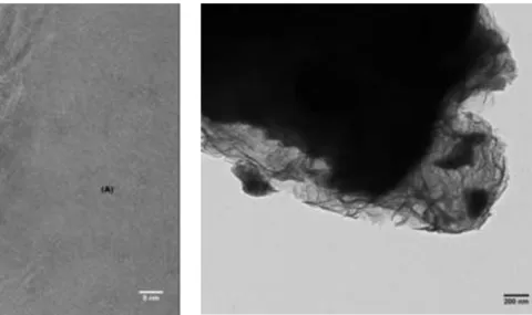
Eventually, the work reverted to analysis of the carbonation process in water only, so as to build knowledge on the passivation that opposes the dissolution of magnesium-bearing ores in water. Figure 4 shows TEM cross-sections of olivine particles having been exposed to 20 bar of CO2 at 120°C and 180°C.
(A) olivine, (B) passivation layer composed of iron oxide and silica, (C) traces of gold from the FIB thin section preparation process.
Translucent passivation layer - Mg, Si and Fe phyllosilicate - covering unreacted olivine particle.
Figure 4. Visuals of the passivation layers that precipitate around the olivine particles during
aqueous mineral carbonation reaction in water only -TEM pictures after reaction at a) 120°C (3 g.L-1, PCO2=20 bar, 24h reaction time) and b) at 180°C (90 g.L-1, PCO2=20 bar, 95h reaction time).
The passivation process always occurred, and the extent of carbonation, never exceeded 7% in 24 hours. The lower curve in Figure 5 shows a typical carbonation rate at 180°C, for olivine particles. The dotted line indicates the rate and extent of carbonation that could be obtained if one were able to prevent the formation of the passivation layer on the particle surface. This was estimated through geochemical modelling of the whole system applied to the olivine feed size distribution, using the dissolution rate of the fresh un-passivated surface of the ore. This rate was obtained by extrapolating the measured dissolution kinetics back to t=0, based on carbonate amount formed according to TGA/IR analysis.
Time (h) Carb o n ati o n yiel d ( %)
Figure 5. Extent of carbonation for olivine as a function of time (180°C, PCO2=20 bar, 90 g.L-1).
The solid line shows a typical measurement for a magnesium silicate ore (minus 100µm), whereas the dotted line shows the theoretical kinetics expected without passivation.
Next, the research team investigated the idea of preventing the formation of the passivation layers, as a driving-concept for crossing the gap between the two curves from Figure 5. Following the earlier work of Béarat et al. (2006)6, a dedicated reactor was commissioned at the laboratory scale so as to exfoliate the passivation layers as they would form. Remarkable results were obtained, without optimisation of the process conditions, thereby leaving a significant margin for optimisation, both in terms of energy requirement of the overall process and kinetics. The results (Figure 6) were obtained with minus 100µm particles for 5 distinct magnesium silicates also without any thermal pre-treatment for serpentine rich rocks.
0 10 20 30 40 50 60 70 80 90 100 0 5 10 15 20 25 Time (h) Ca rbon ati on yield (%) Olivine We1 Hz1 Hz2 Lz1
Figure 6. Kinetics of carbonation as a function of time (180°C, PCO2=20 bar , 90 g.L-1) obtained
Few modifications of this process were tested, including addition of the standard 1M NaCl + 0,64M NaHCO3 inorganic solution3, which helped reach carbonation yields in
excess of 90% in less than 24 hours. This process, which opens promising avenues for the development of ex-situ mineral carbonation, is the focus of new research that targets industrial feasibility and demonstration.
Environmental assessment
The environmental assessment of ex-situ mineral carbonation has been performed based on LCA methodology (Figure 7). Three scenarios were defined and compared, using a coal-fired power station as the source of CO2 emissions:
(1) without CO2 capture ;
(2) with CO2 capture and geological storage ;
(3) with CO2 capture and ex-situ mineral carbonation.
Coal-fired power
station CO2pipelinetransport by
CO2capture Energetic natural resources Non energetic natural resources Emissions to air Emissions to water Emissions to soil CO2storage Waste
Figure 7. Life cycle of the system studied
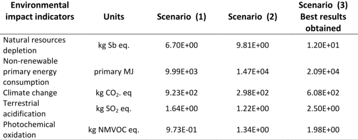
Table 4. LCA results for each scenario studied Environmental
impact indicators Units Scenario (1) Scenario (2)
Scenario (3) Best results
obtained
Natural resources
depletion kg Sb eq. 6.70E+00 9.81E+00 1.20E+01
Non-renewable primary energy consumption
primary MJ 9.99E+03 1.47E+04 2.09E+04
Climate change kg CO2. eq 9.23E+02 2.98E+02 6.08E+02
Terrestrial
acidification kg SO2 eq. 1.64E+00 1.22E+00 2.50E+00
Photochemical
oxidation kg NMVOC eq. 9.73E-01 1.34E+00 1.98E+00
The evaluation showed mixed results with pollution gains or transfers depending on the process and the studied impact indicators (Table 4). However, with the best set of operating conditions and performance obtained using the aqueous mineral
carbonation process, the net result from LCA for mineral carbonation shows promises. It is noted that the research work on the process itself was not optimised; hence there remains a significant margin of improvement. The analysis confirmed however that the viability of this CO2 storage option is mainly at the level of the mineral carbonation
process and optimization of its operating conditions.
Conclusion
This article did propose an overview of the main outputs from the French Carmex project (2009-2012). This project reviewed the feasibility of ex-situ mineral carbonation in terms of resource availability, performance of the aqueous mineral carbonation process and life cycle analysis criteria. Firstly, the project demonstrated the value of SIG for identification and ranking of potential sites. Through a real team effort, the project was able to achieve significant conversion rates, using a process capable of preventing the formation of passivation layers around the particles. Life cycle analysis of the system as a whole led to the conclusion that the eligibility of ex-situ mineral carbonation as a practical solution to CO2 mitigation depends primarily on the operating conditions of the process. This result indicates that more development work is required to optimise the process, however results obtained during this project suggest that admissible conditions are within reach, particularly in favourable situations such as with the New Caledonian context.
Acknowledgements
This research (Carmex Project No. ANR-08-PCO2-002) was co-funded by the French National Research Agency under the CO2 Capture and Storage programme and by Total
(thesis). Special thanks to P. Galle-Cavalloni (BRGM) for his contribution to the experimental work and to BRGM’s Laboratory Division.
References
1. Picot, J.C., Cassard, D., Maldan, F., Greffié, C., Bodénan, F., 2011. Worldwide potential for ex-situ mineral carbonation, Energy Procedia, 4, 2971 – 2977.
2. Bonfils, B. (2012) PhD thesis, Toulouse University
3. Gerdemann, S.J., W.K. O’Connor, D.C. Dahlin, L.R. Penner et H. Rush, 2007. Ex situ aqueous mineral carbonation. Environmental Science and Technology, 41, 2587-2593.
4. Bonfils, B., Julcour, C., Guyot, F., Chiquet, P., Bodénan, F., Bourgeois, F., 2012. Feasibility of direct aqueous mineral carbonation using dissolution enhancing organic additives, In-ternational Journal of Greenhouse Gas Control, 9, 334–346.
5. Bonfils, B., Bourgeois, F., Julcour, C., Guyot, F. et Chiquet, P., 2011. Understanding the chemistry of direct aqueous carbonation with additives through geochemical modelling, Energy Procedia, 4, 3809–3816.
6. Béarat, H., McKelvy, M.J., Chizmeshya, A.V.G., Gormley, D., Nunez, R., Carpenter, R.W., Squires, K., Wolf, G.H., 2006. Carbon Sequestration via Aqueous Olivine Mineral Carbonation: Role of Passivating Layer Formation. Environ. Sci. Technol., 40, 4802-4808.