IAC-11-C2.8.2 Page 1 of 13 IAC-11-C2.8.2
ULTRATHIN EUV FILTERS TESTING AND CHARACTERIZATION UNDER HIGH SOLAR FLUX (13SC) FOR SOLAR ORBITER EUI INSTRUMENT
Lionel Jacques
Centre Spatial de Liège, Université de Liège, Belgium, [email protected]
Jean-Philippe Halain, Laurence Rossi, Tanguy Thibert, Marie-Laure Hellin, Pierre Jamotton, Emmanuel Mazy, Etienne Renote, Karl Fleury-Frenette, Pierre Rochus
Centre Spatial de Liège, Université de Liège, Belgium
The test setup and characterization parameters of ultrathin EUV filters under high solar flux are presented. These 150nm thick aluminium filters are used at the entrance of the Extreme Ultraviolet Imager (EUI) payload, which is developed at the Centre Spatial de Liège for the Solar Orbiter ESA M-class mission. The solar flux that they shall have to withstand will be as high as 13 solar constants when the spacecraft reach its 0.28AU perihelion. A specific design based on additional ribs has therefore been developed to enhance the thermal behaviour and heat evacuation while preserving its optical properties.
It is essential to assess the design performances under the Solar Orbiter high solar flux. Therefore, thermal vacuum test under 13 solar constants will be performed. The filters temperature profiles will be measured during the tests through infrared imaging. A thermal correlation of the test will then be performed to deduce the filters actual thermal properties to be used in the global instrument geometrical and thermal mathematical models.
I. INTRODUCTION
Scope I.I
The Solar Orbiter mission is a candidate M-class mission in the ESA Cosmic Vision Science Programme devoted to the Sun. It has been selected on February 18th 2010 by ESA’s Science Program Committee (SPC) to enter the so-called definition phase in competition with the two other M-class selected missions Euclid and PLATO. The consolidation phase started in February 2011 and the final selection will be held at the SPC and scheduled in October 2011.
The Extreme Ultraviolet Imager (EUI) instrument was selected as part of the scientific payload of the Solar Orbiter. The EUI instrument and the scientific rationale are summarized in previous papers [1]-[7]. It is developed by a consortium led by the Centre Spatial de Liège (CSL) Prime Investigator and including the Royal Observatory of Belgium (ROB), the Institut d’Astrophysique Spatiale (IAS), the Max Planck Institute for Solar System Research (MPS), the Mullard
Space Science Laboratory (MSSL) and the
Physikalisch-Meteorologisches Observatorium Davos World Radiation Center (PMOD).
The two extreme ultra-violet (EUV) channels on EUI rely on ultrathin aluminium entrance filters, providing a wavelength selection but also a heat barrier to the solar input flux. These filters are thus directly submitted to the very high solar flux that will reach 17.5kW/m² when the Solar Orbiter spacecraft will be at its 0.28 AU perihelion. This paper presents the current
developments made at the Centre Spatial de Liège to ensure that these filters will withstand the Solar Orbiter harsh thermal environment.
Acronyms I.II
AM0 Air mass zero
AU Astronomical Unit
CSL Centre Spatial de Liège
ESA European Space Agency
EUI Extreme Ultraviolet Imager
EUV Extreme Ultraviolet
FOCAL Facility for Optical Calibration at Liège
FoV Field of View
FSI Full Sun Imager
GMM Geometrical Mathematical Model
HRI High Resolution Imager
HRM Heat Rejection Mirror
IR Infrared
SC Solar Constant (1367W/m²)
SPC Science Program Comittee
62nd International Astronautical Congress, Cape Town, SA. Copyright ©2010 by the International Astronautical Federation. All rights reserved. [1] [2] [3] Nomenclature: Specific heat [J/kgK]
Solar spectral irradiance [W/m²nm]
Contact conductance [W/m²K]
Thermal conductivity [W/mK]
Pitch of the mesh [m]
Heat flux [W/m²]
Volumic heat source [W/m³]
Radius [m]
Thickness of the filter [m]
Thickness of the mesh [m]
Temperature [°C]
Width of the mesh [m]
Solar absorptivity [-]
Solar spectral absorptivity [-]
Infrared emissivity [-]
Density [kg/m³]
Stefan-Boltzmann’s constant
II. EUI INSTRUMENT OVERVIEW
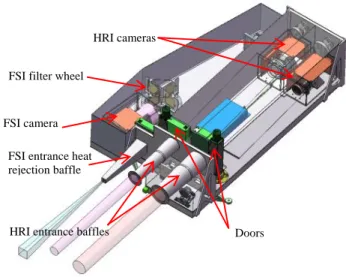
The scientific objectives of Solar Orbiter rely ubiquitously on EUI. The EUI instrument is composed of two high resolution imagers (HRI), observing a portion of the sun at Lyman α (1216 Å) and in the extreme UV (174 Å), and one dual band full-sun imager (FSI) imaging the full Sun alternatively at 174 Å and at 304 Å EUV.
To reject most of the visible and infrared part of the solar spectrum and provide protection against excessive heat input, dedicated filters are inserted between the entrance aperture (entrance pupil at the front of the instrument) and the primary mirrors. The EUV filters are made of 150nm thick Aluminium foil and provide a rejection of visible light which is 108 times more intense than the EUV flux. The Lyman filters are made of an aluminium coating deposited on MgF2 window.
The HRI filters are surrounded by a Heat Rejection Mirror (HRM) consisting in highly reflective spherical mirror designed to reflect the unwanted incoming light which is out of the Field of View (FoV) back to deep space ahead of the spacecraft heat shield. The HRMs are complemented by conical entrance baffles which have a specular reflective coating to reduce light absorption.
During launch, the filters are protected from acoustic vibrations by sliding doors. The heat load absorbed by the entrance baffles, the HRMs, the doors and filters is conductively routed to a thermal interface provided by the spacecraft, itself connected to a dedicated radiator.
Fig. 1 : CAD model of the Extreme Ultraviolet Imager with its main sub-systems
III. PROBLEM STATEMENT AND PRELIMINARY ANALYTICAL MODEL
The FSI aperture pupil is only 5 mm in diameter and the Lyman filter is based on a MgF2 substrate about 10 mm thick. The EUV filter of the HRI channel, whose diameter is also the largest, is therefore the most critical with a diameter of 47.4mm. The dilution provided by the entrance baffle and S/C heat shield feedthrough due to the sun divergence is relatively small (about 5%). The flux impinging the filter at the 0.28AU perihelion is therefore:
( ) ( )
As a first assessment of the filter temperature, a preliminary thermal mathematical model has been built based on the heat conduction equation, where heat radiation is neglected:
The model has also been simplified to a stationary problem to
where is the volumic heat source, the thermal conductivity and the laplacian operator:
FSI entrance heat rejection baffle
HRI entrance baffles FSI filter wheel
Doors HRI cameras
IAC-11-C2.8.2 Page 3 of 13 [4] [5] [6] [7] [8] in cylindrical coordinates assuming a 1-D cylindrical
symmetry. Because of the filter very small thickness, the sun flux can introduced through the volumic source as follows
where is the filter solar absorptivity, and its thickness. One finally gets the filter radial temperature distribution in pure heat conduction regime in function of the external filter radius and external boundary condition ( ) :
( )
( )
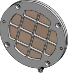
The main parameter in this equation is the thermal conductivity. Due to their very small thickness standard filters are usually reinforced to withstand acoustic vibrations of a spacecraft launch. Commercial Aluminium filters are available and have been used in previous similar EUV space instruments reinforced either with a thin polyimide layer (which reduces the EUV transmission) and/or with a Nickel mesh grid deposited onto the filter (reducing the geometrical transmission). The mesh pitch is typically of 20 to 70 lines per inch (lpi). Fig. 2 shows a standard commercial filter (from LUXEL company) with a 70lpi Nickel mesh.
Fig. 2 : Commercial 70 lpi Nickel mesh supporting a 150nm Aluminium foil filter with closer view under microscope
To avoid modelling in details the Nickel mesh, the concept of equivalent thermal conductivity has been introduced. It is defined as the conductivity that would have a one material filter, of the same thickness of the Aluminium filter, equivalent to the combined Aluminium foil with its mesh. The extra heat conduction provided by the mesh is taken into account by increasing the filter thermal conductivity. The
equivalent thermal conductivity is then associated to the thickness of the filter.
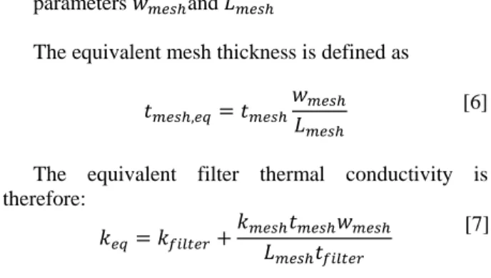
Fig. 3 : Equivalent filter thermal conductivity definition, with geometrical representation of the mesh of parameters and
The equivalent mesh thickness is defined as
The equivalent filter thermal conductivity is therefore:
The equivalent thermal conductivity can then be tuned by choosing the appropriate mesh pitch, width and thickness. This results in a trade-off between the maximum filter temperature and the filter transmission (the denser is the mesh, the lower is the geometrical transmission).
As mentioned, eq. [1] and [5] are only valid if the heat radiation can be neglected which is not necessarily the case since heat radiation becomes quickly significant as the filter temperature increase. First results indeed showed than even with typical mesh dimensions, the temperature of the filter was too high to neglect the heat radiation.
Heat radiation is governed by Stefan-Boltzmann’s law than can be simplified in this case by assuming radiation from the filter front and back sides towards two black-bodies representing the EUI internal cavity (back) and entrance baffles (front):
( ) ( ) where and are the black body front and back radiative environment temperatures, respectively
and and are the front and back filter IR
mesh L mesh L mesh w
62nd International Astronautical Congress, Cape Town, SA. Copyright ©2010 by the International Astronautical Federation. All rights reserved.
[9]
[10] emissivities. Using the equivalent filter thermal conductivity and introducing [8] into [2] as an additional contribution to the volumic heat source , one gets: ( ) ( ) ( ) Fig. 4 shows the filter radial temperature distribution, as numerical solution of this equation, for different equivalent thermal conductivities, in the particular case of , , ,
and . As the equivalent
thermal conductivity decreases, the filter temperature tends to reach its uniform radiative equilibrium temperature, which depends on the radiative boundary conditions and its thermo-optical properties:
√
Fig. 4 : EUV filter radial temperature profile for different equivalent thermal conductivities assuming , and
, and .
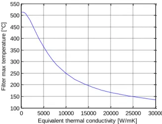
Fig. 5 also shows, as numerical solution of this equation, the filter maximum temperature evolution in function of the equivalent thermal conductivity. If the maximum allowable temperature is 200°C (based on preliminary tests, above this temperature the filter loos its mechanical properties as it will be presented in §IV.II), an equivalent thermal conductivity of 15000 W/mK has to be achieved.
Fig. 5 : Filter maximum temperature in function of equivalent thermal conductivity based on the preliminary model.
Achieving such a high equivalent thermal conductivity would involve too large mesh thickness (already difficult to manufacture but also involving artefacts due to the reflection on the mesh side) and too low transmission as shown by Fig. 6 and Fig. 7.
For this reason, another solution has been developed to further decrease the temperature without reducing too mush the geometrical transmission. The concept is based on clamping a standard meshed filter (20 or 70 lpi) between two Aluminium frames to cut the temperature profile into smaller bumps.
This solution has been modelled and implemented on prototype filters manufactured by the LUXEL company. Filter with patterned mesh matching the contact area between the mesh and the frame have also been procured. These filters will also be tested to determine if their thermo-mechanical properties are better than the standard non-patterned meshed filters with frame.
The commercial filter grid is glued to the aluminium foil, which could be a source of contamination and is not thermally optimum. A new process has therefore been developed at the Centre Spatial de Liège (CSL) to improve the contact between the nickel mesh and the aluminium foil. The technique avoids the use of glue which should ensure a better thermal conductivity.
The commercial and custom made filters prototypes are being tested to validate the principle and correlate the model and the design of the flight model for the EUI instrument, and to assess the new process used to develop the custom filters.
Fig. 8 shows the frame filter concept. The prototype frame is made of two parts, the front and back frames screwed together, clamping the meshed filter foil between them. -20 -10 0 10 20 100 150 200 250 300 350 400 450 500 550 r [mm] T e m p e ra tu re [ °C ] 100 1000 3000 5000 7000 9000 12000 16000 20000 24000 28000 0 5000 10000 15000 20000 25000 30000 100 150 200 250 300 350 400 450 500 550
Equivalent thermal conductivity [W/mK]
F ilt e r m a x t e m p e ra tu re [ °C ] Equivalent thermal conductivity [W/mK] -20 -10 0 10 20 100 150 200 250 300 350 400 450 500 550 r [mm] T e m p e ra tu re [ °C ] 100 1000 3000 5000 7000 9000 12000 16000 20000 24000 28000 0 5000 10000 15000 20000 25000 30000 100 150 200 250 300 350 400 450 500 550
Equivalent thermal conductivity [W/mK]
F ilt e r m a x t e m p e ra tu re [ °C ] Equivalent thermal conductivity [W/mK]
IAC-11-C2.8.2 Page 5 of 13 [11] Fig. 6 : Mesh geometrical transmission in function of
mesh pitch (lines per inch) and width
Fig. 7 : Equivalent thermal conductivity in function of mesh geometrical transmission and width.
Fig. 8 : Frame filter concept, clamping the meshed foil filter. Courtesy: LUXEL.
IV. PRELIMINARY CHARACTERIZATION OF PROTOTYPE FILTERS
Preliminary measurements were performed to characterize the filters absorptivity and maximum temperature they can survive.
Filter solar absorptivity measurements IV.I
The solar absorptivity is a critical parameter of the filter behaviour on EUI because it determines the amount of energy actually absorbed by the filter.
The spectral reflectivity of a 70 lpi meshed filter has therefore been measured over the solar spectrum (250-2500 nm) to deduce the spectral absorptivity, as shown in Fig. 9. The absorptivity of the meshed side is almost two times as high as the one of the other side (Aluminium face) meaning that the meshed side has to be oriented on the anti-sun side within EUI. The solar absorptivity is deducted from the spectral absorptivity as follows:
∫ ( ) ( ) ∫ ( )
where ( ) is the extra-terrestrial (air mass zero, AM0) solar spectral irradiance. In this case, the measured solar absorptivity was 22.1% for the meshed side and 10.3% for the aluminium foil side. It should be noted that these measurement takes into account both the frame and the filter because the size of the measurement spot was larger than a frame cell.
Fig. 9 : Average 70lpi framed meshed filter front and back solar spectral absorptivity. Air Mass Zero (AM 0) ASTM G173-03 solar spectral irradiance is also represented. 10 20 30 40 50 60 70 80 90 100 50 60 70 80 90 100 Mesh width [µm] g e o m e tr ic a l tr a n s m is s io n [ % ] 10 20 30 40 50 60 70 80 90 100 0 20 40 60 80 100 0 2000 4000 6000 8000 10000 Mesh thickness [µm] e q u iv a le n t th e rm a l c o n d u c ti v it y [ W /m K ] 50% 55% 60% 65% 70% 75% 80% 85% 90% Lines per inch
Transmission 10 20 30 40 50 60 70 80 90 100 50 60 70 80 90 100 Mesh width [µm] g e o m e tr ic a l tr a n s m is s io n [ % ] 10 20 30 40 50 60 70 80 90 100 0 20 40 60 80 100 0 2000 4000 6000 8000 10000 Mesh thickness [µm] e q u iv a le n t th e rm a l c o n d u c ti v it y [ W /m K ] 50% 55% 60% 65% 70% 75% 80% 85% 90% Lines per inch
Transmission 500 1000 1500 2000 2500 0 10 20 30 40 50 Wavelength [nm] S p e c tr a l a b s o rp ti v it y [ % ]
meshed side absorptivity Aluminium side absorptivity
500 1000 1500 2000 2500 0 0.5 1 1.5 2 2.5 S p e c tr a l ir ra d ia n c e [ W /m ²n m ]
62nd International Astronautical Congress, Cape Town, SA. Copyright ©2010 by the International Astronautical Federation. All rights reserved.
Temperature testing IV.II
The filters were submitted to temperature test in order to assess the maximum temperature the filters can withstand. They were heated up to increasing temperatures (100°C, 150°C, 200°C, 250°C, 300°C) for 48h under a dry Ar atmosphere. After each 48h temperature dwell, the filter were inspected before going for the next step. Fig. 10 shows pictures of one patterned mesh filter (wider ribs are matching the frame ones) and one 70 lpi standard mesh filter taken after respectively 300°C and 150°C thermal test. After 48h 150°C exposure, the standard 70 lpi meshed Aluminium foil exhibits ripples which does not appear on the patterned one. Even after having been at 300°C. This is probably due to the better contact between the frame and the mesh of the patterned filter. The ripples may indeed be caused by differential thermal expansion between the Aluminium frame and the Nickel meshed Aluminium foil. The coefficient of thermal expansion of Aluminium and Nickel are quite different (23.10-6 m/m°C and 13.10-6 m/m°C) and when heated up, the Aluminium frame stretches and plastically deforms the Nickel mesh. Going back to ambient temperature, the plastic deformation remains, creating the ripples.
The reason why the patterned mesh did not exhibit such ripples is supposed to be because the meshed filter foil slipped between the two frames therefore allowing differential movements. This result is still under investigation. Ripples could deteriorate the solar flux rejection because the sunlight would not be directly reflected outside the baffles anymore, therefore increasing the global heat absorption. Thermo-mechanical simulation will be conducted to better assess this phenomenon because even if the filter foil is stretched and more flat when it is hot (and therefore reflecting light more straight when it is most needed), thermal cycling could induce fatigue damages.
These results have however shown that the patterned meshed filters prototypes exhibit much better thermo-mechanical resistance to temperature.
Fig. 10 : 70lpi mesh filter after 48 hours at 150°C test (left) and patterned meshed filter after 48 hours at 300°C test (right).
V. DESCRIPTION OF THE TEST SETUP
The prototype filters will next be tested to measure the critical parameter of the filter which determines its maximum temperature:
- The contact conductance between the frame and the foil filter,
- The mesh efficiency
The filters will be illuminated under vacuum and their temperature profile will be measured to derive these parameters.
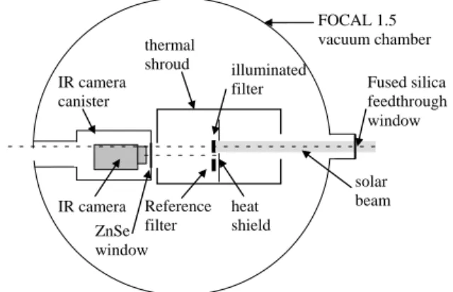
The illumination setup has already been used to test a sun sensor developed in partnership with the company Lambda-X within the frame of the Solar Orbiter mission. It uses a 1000W Cermax PE-1000 13F Xenon lamp that simulates the solar flux. A 7 mm thick fused silica window is used as feedthrough to the vacuum chamber because of its very low light bulk absorption reducing temperature gradient within the window. The chamber used for the test is shown on Fig. 9 and the illumination system is shown on Fig. 10.
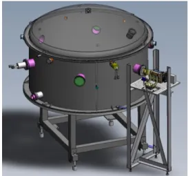
Fig. 11 : FOCAL 1.5 vacuum chamber with the external illumination setup
Fig. 12 : External illumination setup with the 1000W Cermax lamp turned on.
IAC-11-C2.8.2 Page 7 of 13 [11]
Measuring the filter temperature during the test is not obvious because the filter is so thin that any measurement device involving sensors fastened to filter is impossible. An alternative way is to measure the temperature profile used infrared thermography. An IR camera, that cannot be operated under vacuum, will be placed inside a canister with a ZnSe window (thermal IR transparent glass) within the vacuum chamber. The IR camera signal has however three contributions, only one of them representing the actual filter temperature, as shown by Fig. 13:
the self-emitted radiation from the filter (signal)
the environment radiation reflected by the filter (noise)
emission from the atmosphere surrounding the filter (noise)
To improve the signal on noise ratio, it is necessary to reduce the two noise contributions. The atmospheric emission is mostly attenuated by performing the test under vacuum. The filter emissivity being low – about 5% – the environment reflection contribution is inherently high and must be kept below the intrinsic emission of the filter, which is the desired signal. The environment temperature has thus to be much lower than the filter temperature to ensure the energy received by the camera from the environment is much lower the actual energy radiated by the filter:
( )
To limit the reflection contribution to 10% of the emitted radiation, the environment temperature must be 3.7 times lower than the filter temperature, i.e. around 80K for a filter around 300K. This environment is achieved within the chamber using LN2 (liquid nitrogen) circulating in a black painted (85% emissivity) thermal shrouds surrounding the filter.
Fig. 13 : IR thermography measurement principle To decrease the measurement errors, a second similar Aluminium filter is used as reference and is fixed to the cooled thermal shroud, out of the input light beam. As it does not receive any heat load, its temperature is uniform and equal to its mounts temperature which can be monitored by thermal sensors. With this reference filter, the IR camera signal can thus
be calibrated, while measuring the illuminated filter temperature. This calibration however assumes that the aluminium filter emissivity is independent of the temperature, which is the case within the expected temperature range [8].
Fig. 14 summarizes the test setup main elements.
Fig. 14 : Filter conductivity test setup description. The illuminated filter holder and reference filter are protected from unwanted extra light by the heat shield fastened to the thermal shroud.
The filter, whose temperature is measured, is mounted on a holder which is connected to the thermal shroud via three 10mm long, x 5mm wide x 1.5mm thick stainless steel blades. These calibrated blades result in a measurable temperature gradient used to deduce the conductive heat flow from the temperature measurements.
A black painted heat shield is collecting the extra unwanted solar heat flux (as shown in Fig. 14). It consists of a 3mm thick copper plate fastened to the cooled thermal shroud.
VI. THERMAL MATHEMATICAL MODEL OF THE CONDUCTIVITY TEST SETUP
Before testing the filters, thermal simulations have been performed to predict the results and avoid any major issue. Furthermore, this model will be used to correlate the tests results and deduce the filter thermal parameters that will injected in the global EUI thermal model.
Model overview VI.I
The ESATAN-TMS software is used to model the test. However for easier parameterization, the pre- and post-processing of the model is performed in Matlab®. It is used to write the input files (geometry, radiative etc…) and call ESATAN-TMS which computes the radiative exchange factors (GR) and the solar fluxes (QS). The results of the Geometrical Mathematical ( ) ( ) illuminated filter Reference filter Fused silica feedthrough window thermal shroud heat shield solar beam IR camera canister FOCAL 1.5 vacuum chamber IR camera ZnSe window
62nd International Astronautical Congress, Cape Town, SA. Copyright ©2010 by the International Astronautical Federation. All rights reserved.
Model (GMM) are then extracted with Matlab® and inserted in Thermal Mathematical Model (TMM) input file. Additional conductive links (GL) not computed by ESATAN-TMS are also generated with Matlab® and added to the TMM. ESATAN-TMS is again called within a Matlab® script to solve the TMM. The temperature profiles and heat flow maps are then automatically generated and the results saved before starting the next iteration over a particular parameter. This process is depicted in Fig. 15.
Fig. 15 : Processing flow of the test setup thermal model, based on Matlab and ESATAN-TMS software. Solar flux model
VI.II
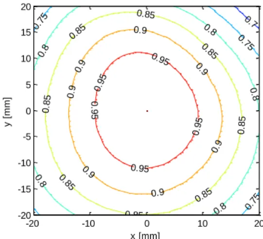
The flux generated by the illumination setup is not perfectly uniform, and using its average value over the filter could lead to some errors. The flux impinging the filter is therefore mapped prior to the vacuum test using a pyranometer (Kipp & Zonen CMP21) and a photodiode (Newport power meter). The beam profile has been mapped and shows a gaussian flux profile with about 80% uniformity in a 13 SC configuration over a 40 mm diameter disc as shown by Fig. 16. The flux intensity can be tuned by moving back and forward the light source, with an impact on the beam uniformity (the further the source, the better is the uniformity).
At 1 SC, the uniformity is about 95%. It has been interpolated from 1 SC and 13 SC for intermediate values. A variable transmissivity window has been used to model this effect in ESATAN-TMS, as shown by Fig. 17 in the 1 SC case. A 27.3% maximum transmissivity of this window has been computed in its centre, with a 26% in the border, for a 5000 W/m² uniform external flux.
The beam divergence has also been taken into account in the model. For a light source at 1 meter from the chamber (corresponding to 16 SC), a divergence of 2.3 arcdeg has been measured. It is similar to the one encountered in the flight conditions (at 0.28 AU, the sun’s divergence is 1.9 degrees.
Fig. 16 : 13 SC (maximum in the centre = 1) solar flux uniformity measurement showing higher than 80% uniformity over a 40 mm disc.
Fig. 17 : Variable transmissivity semi-transparent window used to model the solar flux distribution (here for 1 SC) put in front of the filter.
Filter model VI.III
Fig. 18 shows the Geometrical Mathematical Model (GMM) of the filter. It has been divided into 10x10 nodes in each frame cell. Since the contact is likely not perfect between the frame and aluminium foil, both radiative heat transfer and contact conductive heat transfer with front and back frames are taken into account.
This model is based on the patterned mesh filter. Fig. 18 shows that the filter frame thickness has been geometrically modelled to take into account multiple reflections occurring along the ribs of the frame. For GR & Fluxes GMM TMM GL, QI & C ESATAN-TMS radiative ESATAN-TMS thermal Temperatures Post processing Geometry, thermo-optical properties Matlab Matlab Matlab Parametric analysis
Solar flux & divergence 0.7 0.75 0.75 0.75 0.8 0.8 0.8 0 .8 0.8 0.85 0.85 0.85 0 .85 0.85 0.85 0.85 0 .85 0.9 0.9 0.9 0.9 0.9 0.9 0.9 0 .95 0.95 0.9 5 0.95 0 .9 5 x [mm] y [ m m ] -20 -10 0 10 20 -20 -15 -10 -5 0 5 10 15 20 Solar transmissivity
IAC-11-C2.8.2 Page 9 of 13 manufacturing reasons, the lateral side of the ribs have a
5 arcdeg angle, i.e. they are not perpendicular to the filter plane. In this configuration, a slight concentration effect is expected along the ribs.
The solar absorptivities of the filter that have been considered are the measured ones (10.3% for aluminium side and 22.3% for the patterned mesh side).
An equivalent thermal conductivity of 1669W/mK has been considered as baseline value for the patterned mesh filter. It corresponds to a 41µm x 30µm nickel mesh cross section and 65 lines per inch (391µm) pitch.
Fig. 18 : Geometrical mathematical model (GMM) of the filter. The frame thickness is modelled in order to take into account multiple reflections.
VII. PREDICTIVE RESULTS OF THE CONDUCTIVITY TEST
The main parameters of the test setup thermal model are:
the solar flux,
the filter foil equivalent thermal conductivity ,
the contact conductance between the filter foil and the frame .
Before testing the filters at 13 SC, the filters temperature will be measured at 1 SC and at 5 SC. The baseline values before performing the parametric analyses are therefore 5SC for the solar heat flux, 1669W/mK for the thermal conductivity and 100 W/m²K for the contact conductance.
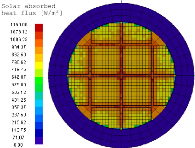
Fig. 19 shows the GMM ray tracing results of the absorbed solar heat flux in the 5 SC case. It confirms that the absorbed solar flux is slightly higher along the frame ribs (11% higher than the cell centre and 23% in the corners of the cell) due to the multi-reflections.
Fig. 19 : 5 SC solar heat flux absorbed by the filter. A slight concentration effect can be observed along the frame ribs and the corners of the frame cell.
Fig. 20 and Fig. 21 respectively show the filter temperature distribution for 5 SC. The front and back frames outer ring are maintained at 62°C with the filter holder being at 61°C. This means that the temperature gradient within the three stainless steel blades holding the filter holder is about 240°C which corresponds to the 0.53W conductively flowing through them as shown on the heat flow map in Fig. 22.
The maximum temperature gradient within the aluminium filter foil is about 40°C with a maximum temperature of 102°C in the central cells. The impact of the frame ribs is clearly visible; dividing the temperature gradient into smaller temperature bumps. This effect is however deeply linked to the contact performance between the frame and the filter.
The 40°C temperature gradient in each frame cell is logically dependent of the equivalent thermal conductivity as it will be shown in the next chapter. These results have been obtained for 5 SC heat flux and a radiative environment which is much cooler that the EUI one, but provide an indication of what the test should provide as results.
Solar absorbed heat flux [W/m²]
62nd International Astronautical Congress, Cape Town, SA. Copyright ©2010 by the International Astronautical Federation. All rights reserved.
Fig. 20 : Temperature distribution over the filter, with 5SC solar heat flux.
Fig. 21 : Temperature distribution in the filter foil with 5SC solar heat flux. The radial temperature gradient within filter foil is below 50°C. The perimeter of the foil is clamped between the back and front frames.
Fig. 22 : Main heat flow map results with 5SC solar heat flux. The filter foil absorbs 74% of the filter total solar heat load, the remaining being directly absorbed by the frame.
VIII. PARAMETRIC ANALYSIS
The impact of the main parameters of the thermal model has then been analysed.
Incident solar flux VIII.I
To reduce the measurement uncertainty and better characterize the filter thermal behaviour, the measurement will be performed for progressively increasing solar heat flux. It is therefore important to assess the expected temperature levels that the filter shall have to withstand.
The solar heat flux will be varied between 1 SC and 13 SC. This is practically done by moving the Xenon lamp away or closer, involving a change in the distribution of the incident solar flux. As explained in §VI.II measurements have been carried out to take this effect into account and the uniformity is adapted for each level between 95% at 1 SC when the lamp is far away and 80% at 13 SC when it is closer.
Fig. 23 : Evolution of the temperature profile in function of the incident solar heat flux. Top plot shows the temperature of the filter and bottom plot shows the temperature delta with respect to the filter frame
-20 -10 0 10 20 -20 -15 -10 -5 0 5 10 15 20 Temperature [°C] x [mm] Frame boundary y [ m m ] 65 70 75 80 85 90 95 100 -20 -10 0 10 20 -20 0 20 60 70 80 90 100 110 x [mm] y [mm] T e m p e ra tu re [ °C ] 0.78 W meshed foil 0.32 W 0.11 W 0.35 W 0.27 W
front frame shroud back frame
0.07 W 0.09 W 0.53 W 0.13 W 0.40 W 0.34 W 0.02 W holder 2.67 W -0.08 W 0.09 W 0.10 W
front shield shroud
conductive heat flow solar heat input
radiative heat flow
-20 -10 0 10 20 -100 -50 0 50 100 150 200 250 300 x [mm] T e m p e ra tu re [ °C ] 1 SC 3 SC 5 SC 8 SC 10 SC 13 SC -20 -10 0 10 20 0 20 40 60 80 100 x [mm] T = T fil te r -T fr a m e [ °C ] 1 SC 3 SC 5 SC 8 SC 10 SC 13 SC -20 -10 0 10 20 -100 -50 0 50 100 150 200 250 300 x [mm] T e m p e ra tu re [ °C ] 1 SC 3 SC 5 SC 8 SC 10 SC 13 SC -20 -10 0 10 20 0 20 40 60 80 100 x [mm] T = T fil te r -T fr a m e [ °C ] 1 SC 3 SC 5 SC 8 SC 10 SC 13 SC Temperatures [°C]
IAC-11-C2.8.2 Page 11 of 13 Fig. 23 shows the temperature profiles for different
solar heat fluxes with the relative delta-temperature between the filter and its frame.
At 13 SC, the filter frame temperature is as high as 190°C and the aluminium foil reaches 270°C i.e. a gradient of 80°C. The gradient within the three stainless steel blades linking the filter holder to the shroud is thus very large.
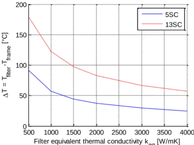
Filter equivalent thermal conductivity VIII.II
The most important parameter of the model, which will be measured, is the filter equivalent thermal conductivity . With the assumptions described in §VI.III, the filter equivalent thermal conductivity is 1670 W/mK. Fig. 24 shows the temperature profiles of the meshed aluminium foil for various equivalent thermal conductivities. Logically, the gradient within the filter and with its frame rapidly increases when the conductivity decreases.
In practical, the equivalent thermal conductivity can be improved by increasing the mesh cross section or by decreasing the mesh step (increasing the number of lines per inch). Nickel is also not a very good thermal conductor and other materials such as gold or copper, of thermal conductivity 4 to 5 times higher, would help to reduce the filter temperature and gradient.
Fig. 24 results have been obtained a 5 SC. At 13 SC, the gradient is larger as shown in Fig. 25 where the evolution of the relative delta-temperature between the filter and its frame is given as a function of the equivalent thermal conductivity for both 5 SC and 13 SC. The gradient at 13 SC is slightly more than twice as high as the gradient in the 5 SC case because of the non-linear radiative influence.
Fig. 24 : Aluminium foil temperature profiles for different equivalent thermal conductivities with 5 SC solar heat flux.
Fig. 25 : Impact of the filter thermal conductivity on the aluminium foil maximum temperature delta with respect to the frame. Red dotted curve corresponds to 13 SC solar heat flux, solid curve to 5 SC.
Contact conductance VIII.III
The last key parameter of the model, that will be characterized with the test, is the contact conductance between the aluminium front and back frames and the aluminium foil.
This parameter is driven by the pressure applied between the two parts, as shown by Fig. 26 from [9], and by the surface roughness. The conductance assumed in the previous computations was 100 W/m²K. Compared to the plot of Fig. 26 it is a low value, but the pressure between the front and back frames and the foil is only provided by a few M2 screws in the filter frame. Furthermore, the contact pressure between the front and back frame ribs in the centre of the filter is likely to be lower than the peripheral pressure.
Fig. 27 shows the aluminium foil temperature profile for different contact conductance values between 10 W/m²K and 10000 W/m²K for both 5 SC and 13 SC. If the contact pressure is reduced, and consequently the contact conductance, the temperature rapidly increases. Between 100 W/m²K and 10 W/m²K the maximum temperature is increased by 80°C in the 13 SC case and the effect of the frame is much less significant. It shows that ensuring a relatively strong contact pressure is crucial to take advantage of the filter frame. However, increasing the contact conductance above 1000W/m²K does not decrease the temperature of the filter, as it is then only driven by the equivalent thermal conductivity.
-20 -10 0 10 20 40 60 80 100 120 140 x [mm] T e m p e ra tu re [ °C ] 5 SC 500 W/mK 1000 W/mK 1500 W/mK 2000 W/mK 3000 W/mK 4000 W/mK 500 1000 1500 2000 2500 3000 3500 4000 0 50 100 150 200
Filter equivalent thermal conductivity k
eq [W/mK] T = T fil te r -T fr a m e [ °C ] 5SC 13SC
62nd International Astronautical Congress, Cape Town, SA. Copyright ©2010 by the International Astronautical Federation. All rights reserved.
Fig. 26 : Evolution of the contact conductance between aluminium plates in function of the contact pressure [9]
Fig. 27 : Aluminium foil temperature profiles in function of the contact conductance between the foil and frame. Top plot shows the results for 5 solar constants and bottom plot for 13 SC.
IX. CONCLUSIONS
The 150nm Aluminium filter used to reject the visible light at the entrance of the EUV channels of the EUI instrument on-board of Solar Orbiter shall have to withstand a very high solar heat flux. A first 1D radiative-conductive model of the filter has shown that the standard mesh grid reinforcement alone could not provide the sufficient equivalent thermal conductivity without drastically decreasing the geometrical transmission. An innovative design based on an additional Aluminium frame clamping the meshed filter has therefore been proposed. This filter has already been submitted to 48h temperature dwell test in a dry environment and their solar absorptivity has been measured. Thermo-mechanical issues have been highlighted by these tests and should be further investigated.
The next critical step is an illumination test under vacuum which aims to characterize the performance of the proposed design. In particular, the equivalent thermal conductivity of the Nickel meshed Aluminium foil as well as the contact conductance with the frame will be addressed. A detailed thermal model of the filter illumination test has been built, including the illumination profile and shroud environment. This model has allowed the prediction of the filter temperature profile that will be measured with an IR camera during the test. The results have shown that the frame could substantially decrease the temperature of the filter foil by dividing the radial temperature gradient into smaller one.
Parametric analyses have furthermore highlighted the importance of the equivalent thermal conductivity and the contact conductance that have to be determined through the correlation of the model with the measurements.
The filter will not directly be submitted to the 13SC solar heat flux and different tests will be conducted at different power levels. The solar heat flux has therefore also been kept as a parameter. For each power level actually performed, the model will be correlated with the measured temperatures to reduce the error on the parameters estimation.
X. PERSPECTIVES & FUTURE WORK
As presented in the conclusions, the next step is the test and correlation with the model to validate the design and deduce the contact conductance and equivalent thermal conductivity.
Thermo-mechanical issues have been highlighted in the temperature dwell test where the patterned mesh filter showed the best results. This issue also occurs in the cold case when the Aluminium foil contracts more that he Nickel mesh grid. Fatigue involved by thermal
-20 -10 0 10 20 60 80 100 120 140 160 x [mm] T e m p e ra tu re [ °C ] 5 SC 10 W/m²K 25 W/m²K 50 W/m²K 100 W/m²K 1000 W/m²K 10000 W/m²K -20 -10 0 10 20 150 200 250 300 350 400 x [mm] T e m p e ra tu re [ °C ] 13 SC 10 W/m²K 25 W/m²K 50 W/m²K 100 W/m²K 1000 W/m²K 10000 W/m²K
IAC-11-C2.8.2 Page 13 of 13 cycling between hot and cold cases should therefore be
investigated.
The cold radiative thermal environment simulated during the test is optimized for the IR measurements. A next step should therefore be to adapt the test setup to simulate the flight environment in order to perform the qualification of the filter. The thermal environment could then be varied to perform the thermal cycling test. The in-flight filter frame interface temperature has been computed as part of the overall EUI thermal model, and is expected to be between 70°C and 80°C in the hot case. In order to perform the qualification tests of a filter with the representative EUI environment, the test setup will have to be modified by replacing the filter holder support with a stronger link to the expected frame interface temperature. Moreover, the flight radiative environment is expected to be around 80°C and not at -180°C.
The baseline frame design considered until here is based on square cells but this may not optimum in term of geometrical transmission. Non-uniform hexagonal cells could potentially be an alternative and will be analysed.
REFERENCES
[1] J.-P. Halain, P. Rochus, T. Appourchaux, D. Berghmans, L. Harra, U. Schühle. F. Auchère, A. Zhukov. E. Renotte, J.-M. Defise, L. Rossi, K. Fleury-Frenette, L. Jacques, J.-F. Hochedez, A. Ben Moussa, The technical challenges of the Solar-Orbiter EUI instrument, Space Telescopes and Instrumentation 2010: Ultraviolet to Gamma Ray, Proceedings of the SPIE, Volume 7732, 419-426, pp. 77320R-77320R-10, 2010
[2] P. Rochus, J.-P. Halain, E. Renotte, D. Berghmans, A. Zhukov, J.-F. Hochedez, T. Appourchaux, F. Auchère, L.K. Harra, U. Schühle, R. Mercier, The Extreme Ultraviolet Imager (EUI) on-board the Solar orbiter Mission, 60th International Astronautical Congress (2009), IAC-09-A3.4.10 [3] Auchere F., Song X., Rouesnel F., Appourchaux
T., Fourmon J.-J., Le Clec'h J.-C., Berthe M.,
Defise J.-M., Mazy, E., Rochus P., Mercier R., Ravet M.-F., “Innovative designs for the imaging suite on Solar Orbiter, Solar Physics and Space Weather Instrumentation”, Proc. SPIE 5901, 298-304 (2005).
[4] Vial J.-C., “Solar Orbiter: A unique opportunity for investigating small-scale physical processes at work in the magnetic solar atmosphere, Advances in Space Research”, Advances in Space Research, 36, 1375-1386 (2005).
[5] Young P. R., and the EUS Science Working Group, “Science With The Extreme Ultraviolet Spectrometer For Solar Orbiter”, Proc. of The Second Solar Orbiter Workshop 641 (2006). [6] Hochedez J.-F., Schühle U., Pau J. L., Alvarez J.,
Hainaut O., Appourchaux T., Auret F., Belsky A., Bergonzo P., Castex M. C., Deneuville A., Dhez P., Fleck B., Haenen K., Idir M., Kleider J.-P., Lefeuvre E., Lemaire P., Monroy E., Muret P., Munoz E., Nesladek M., Omnes F., Pace E., Peacock A. J., Van Hoof C. A., “New UV detectors for solar observations”, Innovative Telescopes and Instrumentation for Solar Astrophysics. Edited by Stephen L. Keil, Sergey V. Avakyan . Proc SPIE 4853, 419-426 (2003).
[7] Hochedez J.-F., Appourchaux T., Defise J.-M., Harra L. K., Schuehle U., Auchère F., Curdt W., Hancock B., Kretzschmar M., Lawrence G., Marsch E., Parenti S., Podladchikova E., Rochus P., Rodriguez L., Rouesnel F., Solanki S., Teriaca L., Van Driel L., Vial J.-C., Winter B., Zhukov A., “EUI, The Ultraviolet Imaging Telescopes of Solar Orbiter”, The Second Solar Orbiter Workshop (2006).
[8] ESA European Space Research and Technology Centre Thermal Control & Life Support Division, Spacecraft thermal control design data, Volume 1 ESA PSS-03-108, issue 1, November 1989
[9] D. Gilmore, Spacecraft Thermal Control Handbook, Volume I: Fundamental Technologies, 2nd ed., 2002, ISBN 1-884989-11-X