Science Arts & Métiers (SAM)
is an open access repository that collects the work of Arts et Métiers Institute of Technology researchers and makes it freely available over the web where possible.
This is an author-deposited version published in: https://sam.ensam.eu
Handle ID: .http://hdl.handle.net/10985/9990
To cite this version :
Nasser Eddine BELIARDOUH, Corinne NOUVEAU, Hakan KALELI - Wear performance of duplex treated low alloyed steel against wood (beech) as static partner - Journal of the Balkan
Tribological Association - Vol. 20, n°1, p.84-92 - 2014
Any correspondence concerning this service should be sent to the repository Administrator : archiveouverte@ensam.eu
* For correspondence.
WEAR PERFORMANCE OF DUPLEX TREATED LOW ALLOYED STEEL AGAINST WOOD (BEECH)AS STATIC PARTNER
N. E. BELIARDOUHa*, C. NOUVEAUb, H. KALELIc
a Laboratoire ingénierie des surfaces (LIS), Université BADJI Mokhtar, BP12;
23 000 Annaba, Algeria
E-mail: beliardouh_23@yahoo.fr
b Laboratoire Bourguignon des Matériaux et Procédés (LaBoMaP), Arts et
Métiers ParisTech de Cluny, Rue Porte de Paris, F-71250 Cluny, France
c Yildiz Teknik Universitesi, Makine Fakultesi, Makine Muhendisligi Bölümü,
Otomotiv Anabilim Dali, 34349 Besiktas, Yildiz, Istanbul, Turkey ABSTRACT
The sliding tribological behaviour of Cr-(WC-Co) coating against wood (beech) as counterpart was investigated using a duplex treatment of low carbon steel(DIN 18CrMo4). The duplex treatment consists of LPC (low pressure carburising) + R.F magnetron co-sputtering of Cr and WC-Co. Pin on disk configurations in dry condition wear tests were performed. The wear scars of the coatings were evalu-ated using optical profilometry, scanning electron microscopy (SEM/EDS) and the wear mechanisms were consequently discussed. The aim of this work is to study wear mechanisms on the wood pin/disc couple. It was concluded that best behaviour was observed in the case of higher Cr content coating.
Keywords: duplex treatment, Cr-(WC-Co) coating, wood, wear. AIMS AND BACKGROUND
Woodworking tools should be hard and need to have low friction coefficient. However, wood cutting tools should not be too hard, because surface of wood must be smooth. In the last decade, some works1,2 were conducted to replace HSS
(high speed steel), carbides (WC-Co) and other ceramics by coatings like CrN or TiN. Chromium nitride family, used for wood cutting tools, shows a superior performance than family of titanium nitride coatings. Tribological tests were car-ried out for several specimens prepared from different types of woods, i.e. oak,
beech, spruce and pine3–5. Abrasive wear properties of a large variety of
conifer-ous wood and hardwood are reported in Ref. 6. Beech wood (Fagussylvatica) has good strength properties, a high abrasion resistance and a density d = 0.73 g/cm3.
It can be cut, planed, drilled and milled easily. Beech is the most abundant broad-leaf tree species in central Europe and the quality of beech round wood is suitable for high quality rotary cut veneer5 in manufacture of furniture, floor, various
car-pentry of the interior. The aims of this study are: (i) to optimise the carburising of the steel substrate and deposition conditions of Cr-(WC-Co) coatings; (ii) to investigate the wear resistance of duplex treated samples against wood (beech) in view to their application on wood cutting tools.
EXPERIMENTAL
Sample elaboration. The substrate used in this work was a commercial low al-loy steel DIN 18CrMo4. Before thermo-chemical treatment, the samples were polished with P800 paper, ultrasonically cleaned, and finally introduced into a vacuum furnace ‘BMI Furnace’. The carburising gas was ethylene (C2H4) and the temperature was 900°C. The total durations of the boost/diffusion stages were 120 min (carburising C1) and 105 min (carburising C2). After the carburising pro-cess, samples are in-situ quenched in a high pressure N2 environment (500 kPa), subsequently annealed at 200°C for 120 min, and finally cooled in a 100 kPa N2 atmosphere. The Vickers hardness values of C1-treated surface layer is Hv.100= 768 ±5 and the C2-treated samples yield Hv.100 = 654 ± 5. Additionally, carbon analysis of the surface layer yields 0.667 wt.% and 0.615 wt.% for C1 and C2 treat-ments, respectively. Both of treated C1 and C2 samples present the same hard-ness’s value at the core of the substrate (Hv.100 ~ 300) and approximately the same depth of carburised layers (550–
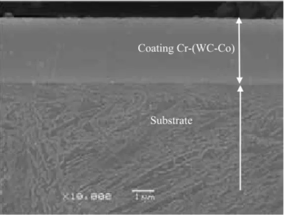
600 µm). A standard and typical microstructure was developed af-ter carburising process. At the top layers, the microstructure consists of martensite phase and cementite (Fe3C) with evidently a few quan-tities of γ retained austenite. After that, Cr(WC-Co) coatings onto carburised surface samples were elaborated as can be seen in Fig. 1.
Deposition of Cr-(WC-Co) coatings was done by RF mag-netron sputtering in a modified commercial system (Nordiko
Coating Cr-(WC-Co)
Substrate
Fig. 1. SEM micrograph: cross-section view of du-plex treated samples. The Cr-(WC-Co) layers devel-oped a dense structure
3500). Substrate to target distance was 8 cm and the base pressure was 6×10⁻⁵
Pa. The targets were Cr (Neyco, 99.95%) and WC-6 wt.% Co(Ampere, 99.5%). The substrates were initially chemically cleaned, followed by a 12 kV DC glow discharge pulsed plasma (25 ms on/50 ms off) for 5 min at an argon pressure of 2 Pa. The chemical composition and mechanical properties of coatings are pre-sented in Table 1. As can be seen, 2 different compositions were obtained by F101 (Cr:W = 1.53:1) and F102 (Cr:W = 1.21:1), respectively.
Samples characterisations. Wear properties of the coatings were evaluated un-der dry sliding condition at room temperature using a pin-on-disk tribometer (CSM HT1000) and Tribox 4.1.1 software. The two main standards referring
to the pin-on-disk tribometer are DIN 50324 and ASTM G 99 – 95a (Ref. 7). The pin-on-disc tests were performed with the test configuration sche-matically illustrated in Fig. 2. The pin wood with a diameter of 6 mm is positioned at 45° on the holder and loaded against a rotating disc. Only cemented (C1 and C2) and cemented +coated (F101 and F102) samples were studied.
In order to approach real contact conditions, e. g. the wood process as peeling of beech, test param-eters were chosen appropriately as listed in Table 2. A particular preparation is needed when tests are conducted with wood counterpart: the pin was cut perpendicular to fibres (length 20 mm; ∅ of 6 mm) from a specific specimen of beech tree provided by a regional sawmill. It was then polished to remove any chips and immersed into hot water (70–75°C) for 24 h.
After the tribo-tests, the profiles of the wear tracks were measured by 3D optical profilometry(VEECO, Wyko NT-1100) and the wear rate was calculated us-ing conventional equations. The wear tracks, wear debris and edges of wood pin were analysed by
Table 1. Chemical composition and mechanical properties of coatings Coatings
code
Chemical composition
(at. %) O2 ~ 0.7 Thickness(µm) Hardness(GPa) The Young modulus(GPa)
C Cr Co W
F101 22.3 41.6 8.3 27.1 2.3 26.4 324.1
F102 23.3 35.4 8.8 31.8 2.2 26.7 331.3
Table 2. Parameters of experi-mental wear tests
Parameters Humidity Sliding speed Normal load Track radius Sliding distance Temperature 40% 2 cm/s 5 N 4 mm 200 m 20°C 45° 2 1 3 1 – pin holter 2 – pin wood 3 – disk
SEM/EDS, using a Jeol JSM-5900LV microscope. RESULTS AND DISCUSSION
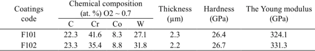
Coefficient of friction evolution. As can be seen in Fig. 3a, when sliding against the wood pin, the coefficient of friction (COF) of the C1 specimen at the start in-creases rapidly after that it dein-creases slightly. Then it reached a maximum value of 0.65 (500 cycles), followed by a sudden decrease to 0.25 (6000 cycles). This phenomenon is also observed when the applied load equals to 1 N. At the end of test, the friction coefficient increases to its maximum value of ~0.8–0.85. How-ever, the coefficient of friction of the C2 sample rises slowly and gets stabilised at the end of test about 1–1.2 (Fig. 3b). Both curves show a run-in period followed by a friction coefficient increase. The C1 sample presents a lower COF (0.85) than the C2 sample (1.15) after 8000 cycles of sliding against wood pin.
When duplex treated samples were tested, the coefficient of friction showed a run-in period, and afterwards an increase in slope of curves, as can be seen in Fig. 3. The F102 coating had a high run-in friction and showed a short period of
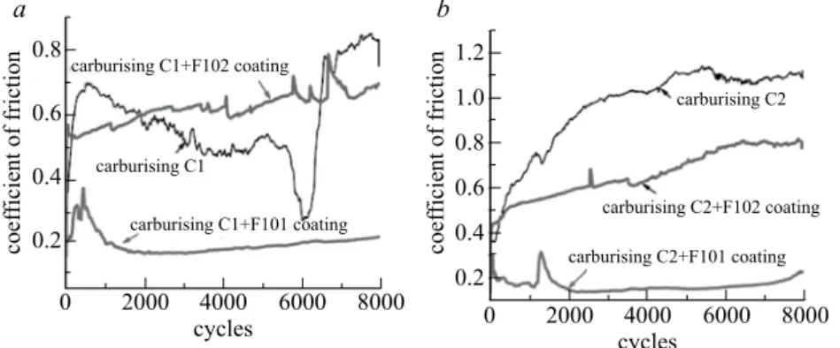
stabilised COF of around 0.6–0.65 for (C1+F102) and (C2+F102). On the contrary, the F101 coating shows a nearly constant evolution of COF. For both (C1+F101) and (C2+F101) samples, after a run-in period, a value about 0.2 was reached. Wear analysis. After a tribotest, SEM analysis of the uncoated samples surface revealed a large wear track (1.5–1.8 mm), and substantial amount of wear particles on its edges. These remarks are valuables for all samples treated C1 and C2. An example of wear track of disk seen on C1 samples is shown in Fig. 4a: inside the circular wear track, wear debris were formed. SEM micrographs show also finest and parallel grooves as result of ploughing by oxide particles (third body wear).
0.8 0.6 0.4 0.2 coef ficient of friction coef ficient of friction 0 2000 4000 6000 8000 cycles 0 2000 4000cycles 6000 8000 1.2 1.0 0.8 0.6 0.4 0.2 carburising C1+F102 coating carburising C2+F102 coating carburising C2+F101 coating carburising C1 carburising C2 carburising C1+F101 coating a b
Fig. 3. Friction behaviour of the duplex treated samples(C1.2 +F101 and C1.2+F102) compared with
Moreover, the wear scar of the counter face, i.e. the edge of the pin wood became smooth as reported in Fig. 4b. Some particles (oxides) are incrusted inside the fibber of wood and a few ‘chips’ are formed at its circumference. Thus initially, at the asperity contact tips, formation of oxides film and, after reaching a critical thickness, breaking of this oxide film (cracks in Fig. 4a) occur as debris forma-tion. Consequently the first step of wear mechanism for the cemented samples sliding against a wood pin is an oxidative wear and the second step is a mild abrasive wear mechanism.
All of the duplex treated samples sliding against pin wood showed the largest wear scar but not very deep (Fig. 5a,b). The coatings are then efficient and well protected by the cemented steel. Few of particles inside circular wear trackwere observed for both coatings F101 and F102 (Fig. 5b). Based on SEM micrographs, no difference was evident between F101 and F102 coating wear tracks was shown and can explain the coefficient of friction evolution in Fig. 3. EDS analysis of the
cracks 1.76 mm 200 µm grooves particles 100 µm inserted particles from wear debris
S.D S.D
edge of pin = worn surface
a
b
Fig. 4. Example of SEM micro-graphs of: wear track on disk carburized C1 (a) and the cor-responding counterpart worn surface of pin wood after pin-on-disk test (b). The insert image was obtained by CATIAV5 software
worn surface and the debris inside wear scar (Fig 5 a,b) reveals only the presence of elements of coating (Cr, W, Co): no iron (Fe) signal or oxygen (O) were found, consequently the wear track is free of oxides. In comparison to the carburised samples and according to the above mentioned results, it can be concluded that the wear mechanism undergone by discs was only a slight abrasion wear.
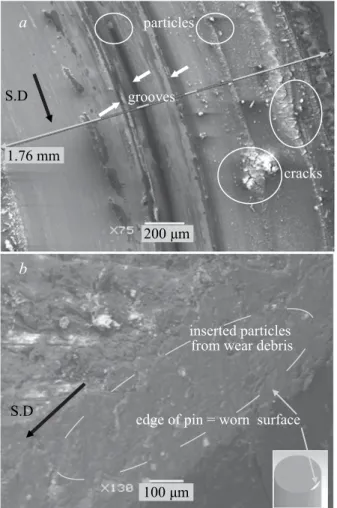
Figure 6 shows the wear scar on wood pin after 200 m sliding distance against duplex treated samples. Considerable difference exists between surface morphol-ogy of pin edge after sliding against F101 (Fig. 6a) and F102 (Fig. 6b) coatings. The wear scar of the pin in the case of the F101 coating shows few quantities of particles, dispersed on a smooth wood surface. These particles contain metallic and organic elements of wood as revealed by EDS analysis spectra. Again, no iron peak (Fe) or oxygen (O) were detected; that proves that coating in not en-tirely destroyed yet. Therefore, the detachment of the coating was presented in the form of wear debris. Some scratches (furrows) parallel to sliding direction are also present and are caused by particles (no oxides) between the contact surfaces. The small amount and size of the observed particles are not sufficient to cause an abrasive wear mechanism. Besides, the COF evolution curve of the F101 coating (Fig. 3), regardless the substrate, indicated that was a mild wear compared to the
Fig. 5. Duplex treated samples: example of SEM micrographs of wear tracks and corresponding EDS spectra at point ‘x’: C1+F101 (a) and C1+F102 (b)
W W W Cr Cr Cr Co W b X W 800 µm 1 2 3 4 5 6 7 8 9 10 11 kev kev S.D S.D 1 2 3 4 5 6 7 8 9 10 11 a X 800 µm C O Co W Co W Cr Cr CoW W
F102 one. As a consequence, no evidence of abrasive wear was found. We sup-pose that movement of particles during sliding can be due to rotation or rolling as reported in literature8–10. The coatings are worn gradually, slowly and with
continuous wear with micro-chipping of small coating fragments in connection to surface defects. The SEM micrographs of the pin worn surface sliding against F102 is shown in Fig. 6b. This part of the wear scar shows a significant amount of adhered counter material which indicates a stronger adhesion between contact surfaces. This is in agreement with the corresponding friction curve in Fig. 4, which shows significantly higher and more fluctuating values as compared with the friction curve displayed by F101 coating. The wear mechanism in this case is adhesive.
Quantitative analysis. From the wear track profile obtained by 3D profilometry, the volume loss and wear rate of disc were calculated, for all the samples. The wear scar of the counterpart (pin wood), is an ellipse. Then major and minor semi-axes were measured by profilometry and to calculate the volume loss CATIAV5 software was used (see the inserted image in Fig. 4b). The results are presented in Fig. 7.
Fig. 6. Example of SEM micrographs of worn surfaces of wood pins against C1+F101 (a) and against (C1+F102) (b). EDS analysis spectra carried out the particles indicate by X
300 µm S.D X a particles S.D 300 µm furrows W W Co Cr Cr W W Na O Cr C 1 2 3 4 5 6 7 8 9 10 11 W W Co Cr Cr Ca K Cl W W Na Cr C 1 2 3 4 5 6 7 8 9 10 11 X b kev kev
The highest wear rate was ob-tained for wood pin and the lowest for the duplex treated samples. An inter-mediate wear rate is observed for the cemented samples. This is probably due to the softer hardness of the wood pin in comparison to the cemented and duplex treated steel samples. Be-sides, the cemented samples showed a similar wear rate value as the duplex C1/F101 and C2/F101 or C1/F102 and C2/F102 treated samples. Neverthe-less, the duplex treated samples (wear rates K of about 1 to 2×10⁻⁶ mm3/N m)
were much more wear resistant than
the only cemented ones (wear rates K of about 7×10⁻⁶ mm3/N m).
It can also be seen that the F101 coating has a lower wear rate than the F102 one probably due to its low COF (0.2). This confirms SEM analysis and the COF evolution curves.
CONCLUSIONS
According to the above-mentioned results the following conclusion can be made: – An oxidative followed by an abrasive wear mechanism is observed when cemented samples were in contact with a wood pin.
– After sliding against the duplex treated samples, the severity of sliding friction depends strictly on the adhesive interactions of the wear debris. In the case of the F101 (Cr:W = 1.53:1) coating, a few and small metallic particles were detached and trapped between the contact surfaces, acting as a protective layer and thus reducing the friction coefficient while an adhesive wear characterised by larger and metallic debris was observed for the F102 (Cr:W = 1.12:1) coating;
– If the application of the steel is wood machining, the C1/F101 or C2/F101 duplex treatments are recommended to protect the steel cutting tools against wear and to have the lowest COF;
– The effect of a duplex treatment is obvious here to improve the wear re-sistance of the steel in comparison to carburising and in view to apply it in wood machining.
ACKNOWLEDGEMENT
The authors would like to thank Dr. M. J. Walock, Dr. A. Zairi, Pr. P. Jacquet, and D. Lagadrillère for their support in the experimental work.
Fig. 7. Estimated wear rates of the tribological couple wood pin/disc
20 15 10 5 0 disk wood pin wear rate ( ×10 –6) (mm 3/N m) C1 C1+F101C2+F101 C2C2+F102C1+F102 samples
REFERENCES
1. M. A. DJOUADI, C. NOUVEAU, P. BEER, M. LAMBERTIN: CrxNy Hard Coatings
Depos-ited with PVD Method on Tools For Wood Machining. Surf Coat Tech, 133, 134, 478 (2000). 2. C. NOUVEAU, E. JORAND, C. DECÈS-PETIT, C. LABIDI, M. A. DJOUADI: Influence of
Carbide Substrates on Tribological Properties of Chromium and Chromium Nitride Coatings: Application to Wood Machining. Wear, 258, 157 (2005).
3. B. WARCHOLINSKI, A. GILEWICZ, Z. KUKLINSKI, P. MYSLINSKI: Hard CrCN/CrN Multilayer Coatings for Tribological Applications. Surf Coat Tech, 204, 2289 (2010). 4. B. WARCHOLINSKI, A. GILEWICZ: Multilayer coatings on tools for Woodworking. Wear,
271, 2812 (2011).
5. E. TANRITANI , S. HIZIROGLU, N. AS: Effect of steaming time on surface roughness of beech veneer. Build Environ, 41, 1494 (2006).
6. T. OHTANI, K. KAMASAKI, C. TANAKA: On Abrasive Wear Property During Three-body Abrasion of Wood. Wear, 255, 60 (2003).
7. ASTM G99 – 95c, Standard Test Method for Wear Testing with a Pin-on-Disk Apparatus. 8. F. H. STOTT: The Role of Oxidation in the Wear of Alloys. Tribol Int, 31 (1–3), 61 (1998). 9. A. DEACONESCU, T. DEACONESCU: Aspects Regarding the Roughness of Surfaces
Ob-tained by Lapping. J Balk Tribol Assoc, 12 (1), 16 (2006).
10. F. ZIVIC, M. BABIC, N. GRUJOVIC, S. MITROVIC, D. ADAMOVIC, G. FAVARO: A Com-parison of Reciprocating Sliding at Low Loads and Scratch Testing for Evaluation of TiN (PVD) Coating. J Balk Tribol Assoc, 18 (1), 80, (2012).