1’ 39v t
Université de Montréal
Les bases anatomiques du lambeau perforant ostéocutané de l’artère iliaque circonflexe profonde
par
Léonard Bergeron, MD
Département de chirurgie Faculté de médecine
Mémoire présenté à la faculté des études supérieures en vue de l’obtention du grade de Maître ès sciences (M.Sc.)
en sciences biomédicales
novembre, 2006 © Léonard Bergeron, 2006
L—
n
7-V. Ô5
n
n
Université
.1k
de Montréal
Direction des bibliothèques
AVIS
L’auteur a autorisé l’Université de Montréal à reproduite et diffuser, en totalité ou en partie, par quelque moyen que ce soit et sur quelque support que ce soit, et exclusivement à des fins non lucratives d’enseignement et de recherche, des copies de ce mémoire ou de cette thèse.
L’auteur et les coauteurs le cas échéant conservent la propriété du droit d’auteur et des droits moraux qui protègent ce document. Ni la thèse ou le mémoire, ni des extraits substantiels de ce document, ne doivent être imprimés ou autrement reproduits sans l’autorisation de l’auteur.
Afin de se conformer à la Loi canadienne sur la protection des
renseignements personnels, quelques formulaires secondaires, coordonnées ou signatures intégrées au texte ont pu être enlevés de ce document. Bien que cela ait pu affecter la pagination, il n’y a aucun contenu manquant.
NOTICE
The author of this thesis or dissertation has granted a nonexclusive license allowing Université de Montréal to reproduce and publish the document, in part or in whole, and in any format, solely for noncommercial educational and research purposes.
The author and co-authors if applicable retain copyright ownership and moral rights in this document. Neither the whole thesis or dissertation, nor substantial extracts from it, may be printed or otherwise reproduced without the author’s permission.
In compliance with the Canadian Privacy Act some supporting forms, contact
information or signatures may have been removed from the document. While this may affect the document page count, it does flot represent any loss of content from the document.
Université de Montréal faculté des études supérieures
Ce mémoire intïtulé: Les bases anatomiques du lambeau perforant ostéocutané de l’artère iliaque circonflexe profonde.
présenté par: Léonard Bergeron
a été évalué par un jury composé des personnes suivantes: Julio femandez, MD, MSc
président-rapporteur Hubert Labelle, MD directeur de recherche
Louise Caouette-Laberge,
m
Steven Morris, MDcodirectrice codirecteur
Andreas Nikolis, MD, MSc membre du jury
Summary
Background: Perforator flaps are increasingly utilized due to advantages including reduced flap bulk, less donor site morbidity and more donor site options. The deep circumflex iliac artety (DCIA) osteornusculocutaneous flapwithiliac crest has been one ofthe most useful flaps used for mandibular reconstruction. However, its use lias been limited by its bulkiness and added donor-site morbidity due to the inclusion of an “obligatory muscle cuff’ of abdominal muscle. Early resuits at designing a DCIA perforator (DCIAP) flap to circumvent this problem have been varied. Details regarding the location, number, and reliability ofDCIA
musculocutaneous perforators have been conflicting. The purpose ofthis thesis is to comprehensivety document the anatomicat basis ofthe DCIAP flap.
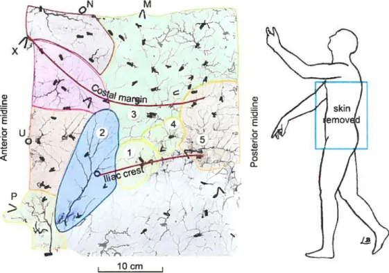
Methods: Six ftesh bodies underwent whole body tead oxide injection (n 12 specimens). Landmarks were identified with radiopaque markers. Dissection, angiography and photography were used to document the precise course of
individual perforators in the flank region. Angiograms were assembîed with Adobe Photoshop and analyzed with Scion Image Beta.
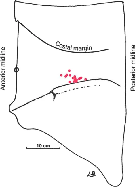
Resuits: An average of 1.6 DCIA perforators with a diameter ofO.7mm were present in 92% ofspecimens. Perforators were Iocated 5-11 cm posterior to the anterior superior itiac spine, 1-35mm superior to the iliac crest, with a perforator zone of3I cm2. The DCIA perfiised the media! aspect ofthe iliac crest.
Keywords: Perforator flap, osteocutaneous flaps, deep circumtlex iliac artery, DCIA, cadaveric study, Iead oxide.
Résumé en français
introduction : Les lambeaux perforants sont de plus en plus utilisés dû aux avantages qu’ils offrent: lambeau plus minces, réduction de la morbidité du site donneur et nombre accru de sites donneurs. Les lambeau ostéomusculocutané « classique» de l’artère iliaque circonflexe profonde a été l’un des lambeaux les plus utilisés pour la reconstruction mandibulaire. Toutefois, son usage n diminué à cause de son large volume et à la morbidité abdominale causéeparl’inclusion d’une« frange musculaire obligatoire». Les résultats
préliminaires sur l’utilisation d’un lambeau perforant ont été variés. Les détails concernant la localisation, le nombre et la fiabilité des perforantes musculocutanées sont conflictuels. Le but de ce mémoire est de documenter en détails les bases anatomiques du lambeau perforant de l’artère iliaque circonflexe profonde.
Méthode: Sixcadavresfraisont été injectés systémiquement avec une solution radio-opaque d’oxide de plomb et de gélatine (nl2 spécimens). Les repères anatomiques de surface ont étés identifiés. La localisation et l’origine exacte de chaque perforante rencontrée dans la région du flanc a été documentée à l’aide de la dissection, l’angiographie et la photographie. Les angiographies ont été aasemblées avec Adobe Photoshop et analysées avec Scion Image Beta.
Résultats: En moyenne, 1,6 perforantes de l’artère iliaque circonflexe profonde étaient présentes chez 92% des spécimens. Le diamètre moyen était de O,7mm. Elles étaient localisées 5-Il cm postérieures àl’épine iliaque antérosupérieureetde 1 à 35 mm
supérieuresàla crête iliaque. L’artère iliaque profonde perfusait la face médiale de la crête iliaque.
Table of contents
SUMMARY
iv
RÉSUMÉ EN FRANÇAIS V
TABLE 0F CONTENTS VII
L1ST 0f TABLES X
LIST 0F FIGURES Xi
LIST 0F ABBREVIATIONS XII
REMERCIEMENTS
xiii
1 INTRODUCTION I
2 CRITICAL REVIEW 0F 111E LITERATURE .. 2
2.1 TI1E DEVELOPI’vIENT 0F PERFORATOR f LAPS 3
2.1.1 Plastic surgely and the dfficultwound 3
2.1.2 Angiosomes andpeforatorzones 4
2.1.3 Vascrtlar anatomy andflapdesign 5
2.1.4 Freeflops in reconstnictive suigety 6 2. 1.5 Peiforatorflops: a revolutioninreconstructive surgery 7 2.1.6 Advantages and disadvantages ofperforatorflaps 2
2.2 MANDIBULAR RECONSTRUCTION $
2.2.] î-Jistoty 9
2.2.2 Osteocutaneousfree flops as the reconstructive n;ethod ofchoice 10 2.3 DEEP CIRCUMFLEX ILIAC ARTERY OSTEOMYOCUTANEOUS FLAP WJTH ILIAC CREST 12
2.3.1 flac des! vascularizallon 13
2.3.2 Refining the bony component 14
2.3.4 Addingperitoneurnfor infra-oral lining .15
2.3.5 Bulkproblerns 15
2.3.6 Strategies to reduce soft-tissue bulk 16 2.4 DEEP CIRCUMFLEX ILIAC ARTERY OSTEOCUTANEOUS PERFORATOR FLAP 16
2.5 CLINICAL OUTCOMES 17
2.5.1 Outcome ofthe DCM osteornusculocutaneousftap 18 2.5.2 Outcome qflhe DCIA osteocutaneous peiforatorfiap 18
2.6 METHODS FOR INVESTIGATING TISSUE VASCULARITY 19
2.6.] Presentation ofarticle 1 19
2.6.2 Article 1: A review ofvascutar injection techniquesfortue study ofpeiforatorflaps 20
2.6.3 Comparison 0fdffferent investigation inethods 29
2.7 LITERATURE REVIEW SUMMARY 29
3 RESEARCH QUESTIONS AND HYPOTHESIS 30
3.1 ARE THEREDCIAPERFORATORS9 31
3.2 Do DCIAPERFORATORS HAVE COMMON CHARACTERISTICS9 32 3.3 DoTHESEDCIAPERFORATORS CHARACTERISTICS ALLOW THE DISSECTION 0F ADCIA
PERFORATOR FLAP9 32
4 METHODS .. .. -. 35
4.1 BODY DONATION AND ETHICS APPROVAL 35
4.2 INCLUSION AND EXCLUSION CRITERJA 35
4.3 PRELIMINARY STUDIES 36
4.3.1 Embalmed cadavers 36
4.3.1.1 Grossdissection 36
4.3.1.2 Ink injection 37
4.3.2 fresh cadavers 37
4.4 TECHMQUE .39
4.4.1 Presentation ofarticle 2 39
4.4.2 Article 2: The anatomical basis ofthe deep circumfiex iliac artery perforatorflap
(DCJAP) with iliaccrest 40
4.4.3 Whole body lead oxide-getatine infusion 65
4.4.4 Dissection 65
5 RESULTS .. ..
6 DISCUSSION 66
6.1 REVIEW 0f MAIN FINDNGS 66
6.2 SIGNIFICANCE 0F MAIN FINDINGS 66
6.3 LIMITATIONS 67
6.3.1 Limitations ofthe method 67
6.3.1.1 Vessel measurements 67
6.3.1.2 Cutaneousterritotymeasurements 69
6.3.1.3 Prediction ofthe maximal eutaneous territory 69
6.3.1.4 Transposition of findings to a clinical setting 70
7 CONCLUSION
-Lïst of tables
Table 1. Osteocutaneous free flaps .11
Table 2. Comparison ofcutaneous territories as measured by photography and
Lïst of
figures
List of abbrevïations
ASIS Anterior superior iliac spine
DCIA Deep circumflexillacartery
DCIAP Deep circumflex iliac artery perforator
Remerciements
Merci à Dr Steven Morrispour m’avoir aidé dans le cheminement intellectuel nécessaire à la réalisation de ce projet. Merci de m’avoir accueilli et supporté si gracieusement.
Merci à Dr Louise Caouette-Laberge pour la planification de ce projet, sa logistique et son encouragment continuel.
Merci à Dr Maolin Tang pour sa précieuse aide avec ses connaissances anatomiques étendues et pour l’aide apportée durant les centaines d’heures de méticuleuses dissections.
Merci à Dr Hubert Labelle pour l’encadrement académique et ses précieux conseils.
Merci à Dr Amétie Botirget pour le support apporté tout au long de ce processus.
Funding provided by:
Capital District Health Authority Research foundation, Halifax, Nova Scotia, Canada
Department ofSurgery, Daihousie University, Halifax, Nova Scotia, Canada IRSC. Programme MENTOR, Microprogramme en mobilité et posture
I
Introduction
Perforator flaps are revolutionizing plastic surgery. Refinements in vascular anatomy knowledge aÏlow more precise isolation ofblood vessels supplying the skin and sparing ofunnecessary tissue components. Musculocutaneous flaps14 are currently the most widely used flap type when skin is needed. The perforator flap concept allows the exclusion of muscle—a passive vessel carrier— in the flap
design. This has contributed to diminish donor site morbidity as well as decreasing flapbulk. One ofthe areas in which this concept could be applied is mandibular reconstruction.
The deep circumflex iliac artery (DCIA) osteocutaneous flap with iliac crest has been one ofthe major flaps used for mandibular reconstruction since its
description in 19795,6. It is known for the large amount of vascularized bone
available, the similarity in shape between the iliac crest and the mandible7, and its vascular pedicle length and size5’6.
Anatomical research has allowed precise characterisation of various flap coinponents and improvements over the original flap design have been achieved. The inner cortex ofthe iliac crest is mainly supptied by the DCIA through
periosteal circulation6. This allows the longitudinal spiitting ofthe crest8’9 to reduce fiap bulkanddiminish donor site morbidity. The iliac crest can also be
osteotomized to better fit the jaw contour as long as the periosteum along the medial aspect ofthe iliac crest is lefiintactt0.Others have characterized the
contribution ofthe DCIA to the internai oblique muscle”, which bas been used to facilitate ciosure ofthrough and through oromandibular osteomucocutaneous defects’2
Despite the numerous advantages ofusing the iliac crest, the widespread use ofthe DCIA flap has been Iimited by the unnecessary buik ofthe “obligatory muscle cuff’ and the tethering ofthe skin to the bone which renders soft tissue placement problematic in complex oromandibular reconstructions.’315 Pioneering efforts by Safak’3andKimata’4”5 at designing a DCIA perforator (DCIAP)’6 flap to reduce the soft-tissue bulk ofthe flap have had limited success. There are only 7 cases reported in the Iiteratur&3’5.
The purpose ofthis thesis is to establish the anatomical basis ofa reliabie DCIAP flap for mandibuiar reconstruction. A critical review ofthe Ïiteratcire is conducted first. it is then foilowed by a description ofthe methods used, which includes a review article on vascular investigation techniques. A second article on the anatomical basis of the DCIAP flap constitutes the core ofthis thesis. An expanded discussion is included in this document, along with a conclusion.
2
Critïcal review of the literature
This section reviews thehistoryof perforator flaps, mandibular
reconstruction, and development of the iliac crest free flap as the reconstructive method ofchoice. The objectives ofthe pioneering efforts to deveiop a DCIA perforator flap were to reduce donor site morbidity and to diminish the soft-tissue
bulk ofthe classic DCIA osteomyocutaneous flap. The development and clinical use ofdifferent DC1A flaps is discussed herein. Finally, methods for investigating tissue vascularity and perforator flaps are reviewed.
2.1
The development of perforator flaps
2.1.1 Plastic surgery and the difficuit wound
Historically, Plastic Surgery has been concerned withthe closure ofdifficult wounds which can be the consequences of disease, trauma or oncologie surgery. The plastic surgeon’s arsenal consists ofdifferent grafting or tissue transfer techniques. A grafi is a piece of tissue which relies entirety on its recipient bed to meet its metabolic demands as it does flot have its own blood supply. A flap, is a mass oftissue(s) which is supplied by itsown arteryand vein: the pedicle. Free tissue transfers invoive either a graft or a flap that is taken from a donor site and “transplanted” to a recipient. Theartery and vein ofthe flap are anastomosed to an arteryand vein at the recipient site using special microsurgical instruments and a microscope, a technique called microsurgery. Grafis and flaps can be made ofone or many constituents: skin, muscle, bone, tendon, nerve, adipose tissue, etc. As a general rule, grafts are usually smaller and thinner as they rely on donor site
diffusion to rneet their metabolic requirements. Larger and more complex grafis are tess reliable as blood and nutrients fails to reach ceils away from the recipient site. Flaps are flot restricted by such size timits as they have their own circulatory system.
The required tissue constituents for closure of a wound are dictated by the wound characteristics. A cutaneous deficit requires skin for closure, a bone deficit requires bone for closure, a tendon deficit requires tendon, etc. In the same way, a multi-Iayered deficit ideally requires a multicomponent flap for closure. The ultimate goal is the restoration of both form and function.
2.1.2 Angiosomes and perforator zones
An angiosome17 is a bloc oftissue(s) or territory perfused by a named artery. An angiosome is to blood vessels what a dermatome is to cutaneous nerves. The human bodyhasmany angiosomes and they are relativeÏy consistent between individuals. For sirnplicity in this document, an angiosome will onty refer to the cutaneous contribution of a named artery. To reach the skin, a named artery gives off smatler branches called “perforators” because these vessels are “perforating” the deep fascia. One (cutaneous) angiosome, or vascular territory, is therefore the cutaneous tcrritoiy supplied by one or many perforators.
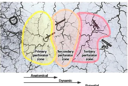
There is no anatomicat term to defrne the integument territory perfused by one single perforator. Cormack and Lamberty in their book on fasciocutaneous flaps’8 used the terms anatomical, dynamic, and potential territories to describe how blood flows from one vascular unit (the anatornical territory) to a second vascular unit (dynarnic territoiy) and even possibly to a third vascular unit (potential territory) through the rich network of choke vessels interconnecting these systems. However, this vocabulary is derived from physiological studies. Anatomy is a static, descriptive science and we preferred devising a more accurate vocabulary for
the purpose of our study. Therefore, the vascular territories are described as primary, secondary and tertiaiy zones (figure 1).
Figure 1. Anatomical and physiologicat definitions of vascular territories.
Perforator zones.psd
2.1.3 Vascular anatomy and flap design
To design a flap for a particular reconstruction, mie must know the precise vascular anatomy ofthe donor area. Surgical incisions in flap design are guided by the angiosomes principle so as to preserve the blood supply to the piece of tissue of interest. Failure to respect this vascular organisation will likely resuit in flap failure, or necrosis. Sir Harold Gillies made the comment19: “Plastic surgery is a constant battie between blood supply and beauty.”
Anatomical
flurnamir
2.1.4 Free flaps in reconstructïve surgery
A ftee flap involves the distant transfer of tissues. It atso requires re establishing its intrinsic circulation by anastomosing an artery and a vein under the operating microscope. Current microsurgery techniques currently allow for suturing ofvessels as small as O,5mm20.
A successfut microsurgical transferrequ ires a precise knowledge ofthe vascular anatomy of both the donor site and recipient areas21. A bloc of tissues, the flap, can then be safely dissected to its pedicle, knowing that it wiIl receive a
sufficient vascular supply and outflow to meet its metabolic demands and allow for its complete survival. The pedicle can then be severed and re-anastornosed at a distatit site to re-estabtish its blood circulation21’22.
The first successful skin free flap was performed in 1973 by Daniel and Taylor2t’22, who demonstrated that a solid anatomical knowledge ofcutaneous vascularization could allow the isolation ofa bloc of tissues on its pedicle and remain viable afler anastomosis at a distant site. Further research demonstrated a consistency in cutaneous vascularization territories known as angiosornes’7, and this provided the anatomical basis for severat free flap donor sites23. A consistency in muscle vascularization was also describedt. This leU to a multitude of
musculocutaneous flaps being used and described in the late 1970s and 1980s’6.
The arrangement ofblood vessels within bone has been disputed for many years and the most widely accepted description was made by Brookes24’25.
flaps have been more useful to identify reliable blood supply to bone for tissue transfer25, than the use ofa general bone vascularization classification.
2.1.5 Perforator flaps: a revolution in reconstructive surgery
f lap design is based on vascular anatomy. During the past decade or two, most flap designs were modified to fitthese vascular territories in an effort to improve tissue vascularity and stirvival. Musculocutaneous flaps in particular, were found to have a very reliable anatomy and were therefore some ofthe earliest flaps used in reconstructive surgery26. A muscle supplied by a large artery and vein supplies musculocutaneous perforators to the overlying skin. When a skin flap was used for reconstruction, the musculocutaneous composite flap was therefore raised en bloc, using the underlying muscle as a passive carrier for vessels supplying the overlying skin. Perforators had been identified, but were overlooked as their anatomy wasjudged unreliabte. Thus, initial flaps were quite bulky, and donor site morbidity was an issue. But this compromise was necessary to maintain the integrity of skin vascularization with current knowledge ofvascular anatomy.
Perforator flaps have revolutionized reconstructive surgery’6. Pioneer work by Koshima27 and Kro1128 has shown that the passive muscle carrier was flot necessaiy to pcotect the course ofperforators. Reappraisal of skin vascutar
anatomy29 and refinement of investigative rnethods30’31 have clearty established that perforators and perforator zones are a clinically useful entity. This new level of vascular knowledge has led to an explosion ofimprovements in current surgical practices3238. However, our abitity to perform successfully ftee tissue transfer has
improved much more than otir knowledge cf anatomy. New perforator flaps potential donor sites are stiil to be found and vascular anatorny principles6”7’23’396 need to be revisited.
2.1.6 Advantages and disadvantages of perforator flaps
The advantages of perforator ftaps are numerous. The isolation of the vascular pedicle and sparing ofunnecessary tissue components decreases donor site morbïdity, provides more versatile flap designs, and improves postoperative
recovery16. It is also thought that the long-term shape ofthe flap is more stable as there is flot atrophy of included muscle.
The main disadvantages cf perforator flaps over musculocutaneous flaps include a longer dissection to isolate the musculocutaneous perforators and variability in the size and position of perforators necessitating a preoperative Doppler examination47’48 to locate those vessels.’6 Moreover, the main factor limiting the development of new perforator flaps has been the lack of anatomical characterization and location of these perforating vessels, which woutd allow more reliable perforator isolation and surgical flap design.
2.2
Mandibular reconstruction
In this section, we will review the history cf mandibular reconstruction, one of the most challenging procedures in plastic surgery49. The evolution from bone grafting to vascularized bone flaps as the method ofchoice te restore mandibular
continuity is discussed, as well as current problems particular to oromandibular reconstruction.
2.2.1 History
Early mandibular reconstruction techniques were developed at the beginning ofthe20thcentury50. in 1916, Delangeniere discussed mandibular reconstruction with a tibial bone graft51’52. The iliac crest for mandibular reconstruction was described the same year by Lindrnan51. Early efforts at improving reconstruction
included delaying mandibular reconstruction, the use of internai wire fixation, and the introduction ofantibiotics during World War Ii50. A multitude ofconventional bone grafis and alloplastic materiai were subsequently used to restore mandibular continuity49.
Aftempts at mandibular reconstruction were complicated in the 1960s. Aggressive resection were performed and followed by radiotherapy which caused bone graft resorption and infection50. Poorly vascularized beds with dysfunctional wound healing were suboptirnal and reconstructive efforts were disappointing49’51. Attempts were made to reduce grafi infection rates by pediculing local
osteomyocutaneous ftaps9’52’53, which brought their own blood supply to the irradiated wound bed. Initial success rates of 35%, dropping to 15% at one year, were disappointing. Other pedicled osteomyocutaneous flaps described have had mitigated results9’50’54’55. Bone resorption was Îess than with grafis but available local bone sources were suboptimal50. This led to the conclusion that pedicÏed fiaps were unacceptable for primaiy rnandïbular reconstruction9.
2.2.2 Osteocutaneous free flaps as the reconstructive method of choïce
Microsurgery and the ability to transfer vascularized tissues22’56’57 from a distant donor site has revolutionized mandibular reconstruction5’6’9’49’5t, one ofthe most difftcult problems in head and neck reconstruction49’58. The surgeon was no more limited by anatomical proximity ofthe donor and recipient sites.
Microvascular composite tissue transfer has since become the rnethod of choice for primary reconstruction of the mandibte51’5961.
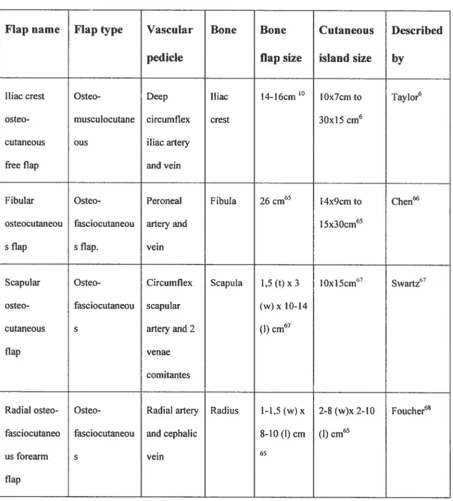
Four osteocutaneous flaps are now commonly used for mandibular
reconstruction60: the iliac crest, the fibula, the radius (radial forearm flap), and the scapula (Table 1). 0f these, the fibula and deep circumflex iliac artery (DCIA) flaps are the two flaps ofchoice6° when large bone deficits are present. The DCIA osteomusculocutaneous flap offers numerous advantages’5. A substantial amount of vascularized bone is supplïed by the deep circumflex iliac artery, which is of large diarneter. The shape ofthe iliac crest with its anterior superior iliac spine is similar to the body ofthe mandible with its angle. A reliable ccttaneous paddle if perfused by the DCIA. Multiple tissue components, such as the internai oblique muscle”62 can be raised on the DCIA pedicle to accommodate complex deficits’2’63’64.
Table 1. Osteocutaneous ftee flaps.
ftap name Flap type Vascular Boue Boue Cutaneous Described pedicle flap size island size by
Iliac crest Osteo- Deep iliac 14-16cm ‘°
lOx7cm to Taylor6 osteo- musculocutane circumflex crest 30x15cm6
cutaneous ous iliacarteiy
free flap and vein
f ibular Osteo- Peroneal Fibula 26 cm65 l4x9crn to Chen osteocutaneou fasciocutaneou arteryand 15x30cm65
s flap s flap. vein
Scapular Osteo- Circumflex Scapula 1,5 (t) x3 10x15cm67 Swartz67
osteo- fasciocutaneou scapular (w) x 10-14 cutaneous s arteryand 2 (1) cm67
flap venae
comitantes
Radial osteo- Osteo- Radial arteiy Radïtis l-1,5(w) x 2-8 (w)x 2-10 Foucher68 fasciocutaneo fasciocutaneou and cephatic 8-10 (1) cm (I) cm65
us forearm s vein 65
2.3
Deep circumilex iliac
artery
osteomyocutaneous
flap with iliac crest
The itiac crest with its overlying skin was readily identified as a potential donor site for an osteocutaneous composite flap in 1972 by Taylor and Watson69. They concluded înitially after their preliminary ink injection and dissection studies in 25 cadavers, that a segment ofthe iliac crest coutd be raised in continuity with its overlying skin, based on the superficial circurnflex iliac artery (SCIA) pedicle. Two clinical cases were reported.
Clinical observations while raising the SCIA osteocutaneous ftap prompted Taylor et aï. to investigate the contribution ofthe DCIA to the area6. The authors performed bilateral ink injection studies in 20 cadavers. They documented stained cutaneous territories and examined 30 ofthe iliac crests microscopically for ink staining. DCIA perforators were counted bilaterally in 10 abdominoptasty cases. Thirty clinical angiograms were also used to confirrn the course ofthe DCIA. They found that the DCIA is a large vessel (2mm diameter) originating from the externat iliac artery, proximal and deep to the inguinal ligament. It then ascends along the inner aspect ofthe iliac crest towards to the anterior superior iliac spine where it gives off a nutrient branch to the bone and an ascending branch which supplies exclusively the muscular components ofthe abdominal val1. The DCIA then pierces the transversalis fascia and transversus abdominïs as it travels posteriorly along the iliac crest. The venous drainage ofthe DCIA system is via venea
cornitantes that parailels the arteriai system5’6. They unite and form a single vein near the inguinal ligament, before draining into the extemal iliac vein5,6,62,70
The DCIA was found clinicatly to give an average of 6 cutaneous perforators in a 2,5cm wide area extending anteriorly ftom the ASIS, to 6cm posteriorly, and bordered by the iliac crest inferiorly. A dominant perforator was found in ail cases. A stained skin area, ranging ftom lOx7cm to 3Oxl5cm, was aiways present. The skin ellipse was centered on a point 4 to 8 cm posterior to the ASIS.
The authors successfully demonstrated the anatomical basis for the superiority ofthe DCIA as the main blood supply to the iliac crest
osteomusculocutaneous flap. They supported their findings by performing 11 clinical cases. Multiple authors subsequently studied the DCIA and its contribution to different tissue components”3’62’7’-75
2.3.1 Iliac crest vascularïzatïon
The iliac crest is known as a reliable source ofboth cortical and cancellous bone ofendochondral origin76’77. Long terni follow-up studies indicate that vascularized bone flaps are superior to bone grafling, as bone grafis undergo a larger and unpredictable volume loss due to resorption7883. The vascutarized iliac crest free flap has therefore been the preferred method of iliac crest transfer for mandibular reconstruction50.
Anatomical6’72’74 and dlinical studies5 have shown that the DCIA is the main blood supply to the anterior iliac crest. It has been recognized that the periosteum of the inner table ofthe illac crest provides sufficient vascularization to the iliac crest bone flap, and this property has been used to design a thinner bone flap that includes oniy the inner cortex of iliac crest flaps8’9. Other vessels contributing directly or indirectly to the vascularization ofthe iliac crest described in the literature include: the iliolumbar84’85, the iumbar86, the superior gluteal8789, the
69 909”
superficial circumflex iliac ,and lateral femoral circumilex - arteries.
2.3.2 Refining the bony component
In 1981, Taylor and Daniel reported the feasibility ofraising only the inner cortex ofthe iliac crest, along with a portion ofthe epiphysis, to promote flap growth in a 13 year-old patient8. Shenaq then applied this flap modification routinely to decrease donor site morbidity and contour deformity in aduit patients9’5’
2.3.3 Adding the internai oblique muscle for intra-oral lining
Rarnasastiy recognized the contribution ofthe DCIA to the f ntemal oblique muscle’1’62 Based on this information9, Urken proposed a triple tissue component fiap (iliac crest, internaI oblique muscle, and skin) based on the DCIA for
mandibular reconstruction’2’63’64. The skin paddle was used to reconstruct the cheek, the iliac crest to replace the mandible, and the denervated internai oblique muscle was used for infra-oral lining and skin grafted. The subsequent muscle atrophy and
retraction would help obtain a beller definition ofunderlying head andneck structures10”2 to ease fitting of dentures.
2.3.4 Adding peritoneum for intra-oral Iïning
To reduce the need for a second flap for intra-oral lining in compound mandibular defects, Karcher evaluated the possibility of including peritoneum to the DCIA flap for intra-oral lining He performed ink and barium studies ofthe DCIA in 32 dissections from 26 cadavers. He found an area of peritoneum that stained with ink, measuring in average 6x1 4cm. One case involved two flap components pedicled on the DCIA: a first classic osseomusculocutaneous DCIA flap was desïgned and a second musculoperitoneal component was made based on the ascending branch ofthe DCIÀ artery. It included the internai oblique muscle, transversus abdorninis muscle and underlying peritoneum. A second case involved only the transfer ofthe transversus abdominismuscle and underlying peritoneum based on the ascending branch ofthe DCIA. A third osteomusculoperitoneal flap (without mention ofthe exact tissue components) was also reported. The authors reported excellent flap vascularization. No hernias were reported at 9 months.
2.3.5 EuIk problems
Factors limiting the use ofthe DCIA iliac crest osteocutaneous flap
oromandibular reconstruction include the bulk’° associated with the inclusion of the “obligatory muscle cuff’5’6, a full-thickness fringe of abdominal muscles raised in continuity with the iliac crest5’6. According to the rnusculocutaneous flap concept, a sufficiently large mass of muscle must be included with the flap to incorporate a
significant number ofmusculocutaneous perforators to supply adequately the overlying skin10. This extra mass can complicate intra-oral reconstruction13’5.
2.3.6 Strategies to reduce soft-tissue bulk
To address the extra bulk associated with the obligatory muscle cuff some authors recommended raising two different flaps: one from the iliac crest and a second thin cutaneous one which would replace the thick musculocutaneous component ofthe DCIA flap. This would also facilitate three-dimensional
placement ofthe soft-tissue component as the integument is usuatly tethered to the underlying muscle. Flaps that have been combined with the DCIA bone flap include: SCIA/DCIA58’94’95, DC{Alradiat forearm96, DCÏA/ulnar forearm flap61, DCiAJtensor fascia lata flaps. Such procedures are complex and lengthy as they require elevation of two separate flaps, two sets of microvascular anastomosis, and closure oftwo donor sites.
2.4
Deep circumflex illac
artery
osteocutaneous
perforator flap
The classical iliac crest musculocutaneous flap5, with its “obligatory muscle cuff’, is quite bulky and complicates oral reconstructio&35. It is recommended that a 3x8 cm ftinge of full thickness abdominal wall musculature be kept in continuity with the iliac crest, even extending anterior to the anterior superior iliac spine (ASIS), to protect the DCIA musculocutaneous perforators. The mobility of the skin component is restricted by its aftachments to this muscular component and
this further complicates reconstructive efforts. With the recent aUvent ofperforator flaps, where the vesselsare isolated from their passive muscle carrier to diminish donor site morbidity16, several authors have questioned the utility ofthis
“obligatory muscle-cuff’ to improve the original design ofthe flap by reducing this bulk and increasing its component mobility’3’5.
Safak et aï.13, in 1997, challenged the “obligatory muscle cuf?’ concept and reported thetwofirst cases ofDCIA osteocutaneous flap without this obligatory muscle cuff Fiehad previously performed bilateral DCIA dissections in 10 non injected cadavers. Three vascularpattemswere identified by the authors. In 40% of cases, the DCIA travel leU deep thetransverszts abdorninisand liberated a series of small musculocutaneous perforators (0,3-0,5mm). In 30% of dissections, the DCIA penetrated the transversusabdominis3-4cm posterior to the ASIS and travelled between the transversus abdominis andthe internai oblique muscle and provided a similar pattern of small musculocutaneous perforators. in the last 30% of
dissections, a dominant rnuscutocutaneous branch was found 5-6 cm posterior to the ASI$ and 1-2cm above the iliac crest. It averaged 1,5mm in diameter and 6cm in Iength. Ris findings contrasted with Taylor’s6 in that he did flot find a consistent “dominant perforator” paffem during his dissections.
2.5
CIinical outcomes
In this section, we will review the fimctional outcomes ofthe classic iliac crest flap and the DCIA perforator flap, as weil as donor site morbidity.
crest flap design can decrease donor site morbidity. Besides reducing flap bulk and facilitating soft-tissue placement, the DCIA perforator flap design is thought to reduce the incidence of abdominal hernia by sparing the “obligatory muscle cuff’.
2.5.1 Outcome of the DCA osteomusculocutaneous flap
Shpitzer and Neligan97 present a retrospective analysis of LI 7 patients who underwent mandibular reconstruction. Fifty-nine percent of flaps used were iliac crests. Three iliac crest flaps were lost. A total of 31 patients in the iliac crest group were available for follow-up. When compared to fibula flap reconstructions, the iliac group demonstrated no statistically significant difference in functional and cosmetic outcome for oral competence, speech, and contour.
David6’ reported his ten-year experience with 32 iliac crest flaps for mandibular reconstruction. One bone flap’s pedicle thrombosed, but survived as a graft. The authors did flot note any donor-site complications.
Forrest studied 78 patients who had 82 iliac crest free flaps. The most ftequently encountered problem at the donor site was sensory change. femoral neuropathies and femoral hernias were infrequent. functional loss resultingfrom ftee iliac crest transfer was found to be acceptable.
2.5.2 Outcome of the DCIA osteocutaneous perforator flap
Safak first described two successful cases of a DCIA osteocutaneous perforator flap13. Based on previously published anatomical data on theDCIA
10 consecutive patients14”3. in 3 patients, a DCIA perforator could flot be found preoperatively with Doppler examination, so the DCIA perforator flap design was rejected. 0f the 7 cases were a perforator was ïdentified, only five were raised as a perforator flap. The perforating vessels were judged too small in the other 2 cases (0,5mm). One hundred percent flap survival was obtained in the DCIA
osteocutaneous perforator flap group. Preservation ofthe abdominal wall muscle integrity is thought to reduce the incidence of abdominal hernias’3’5.
2.6
Methods for investigatïng tissue vascularity
The gold standard for studying skin perforators is the lead oxide-gelatine technique30, which allows reliable visualisation ofvery fine vascular networks.
2.6.1 Presentation of article 1
A review ofthe methods ofvasctilar injection studies for the study of perforator flaps is presented. Our laboratory has improved the Iead oxide-gelatine technique3° to allow constant and reliable visualisation of fine vessels, a
prerequisite for the study of perforator flaps. This information was flot previously available in a summarized form. A section ofthe article expands on our methods.
The role ofDr Bergeron vas to find and summarize historical and current investigation techniques for the study of perforator flaps, as weIl as writing the current article.
2.6.2 Article I: A review of vascular ïnjection techniques for the study of perforator flaps
Bergeron L, Tang M and Morris S F. A review ofvascular injection techniques for the study of perforator flaps. Ptast Reconstr Surg 2006; 117:2050-2057. Reproduced under permissionbythe Editor.
A Review of Vascular Injection Techniques for
the Study of Perforator Flaps
Leonard Bergeron, M.D., C.M. Maolin Tang, M.D. Steven F. Morris, M.D., M.Sc.
Hatifax, Nova Scotia, anat1a
urgeons require detailed, accurate infor mation regarding the anatomy of cutane ous perforating vessels before using specific surgical llaps. With the rapid development and application of perforator flaps in plastic surgery, there has been renewed interest in the vascular anatomical basis of current and potential perfo rator flaps. Traditional injection techniques used for the study of tissue vascularity are often confusing and produce variable resuits. This has led to the refinement and validation of the ra diopaque lead oxide injection technique for the study of microcirculation.1 Other nonra diopaque techniques can potentially be usefiul. Unfortunately, there is no updated account of injection techniques in recent publications. The goals of this article are therefore to (1) review the history of arterial injection techniques; (2) review the modem techniques used for studying surgical flaps; and (3) describe in detail the in jection technique used in our laboratory that provides consistently high-quality angiograms of the vasculature of skin, bone, tendons, muscle, nerves, peritoneum, and viscera.
from the Departrnent of Anatomy and NeurobioÏogy and Surgery, Daihousie University.
Receieed for publication December 8, 2004.
Copyright ©2006 by theArnerican Society ofPlastic Surgeons DOl: 10J097/01 .prs.0000218321.36450.9b
E arly knowledge of vascular anatomy was first obtained from the dissections of anatomists in cluding Herophilus (circa 340 BC), who coined the term “artery”2; Galen (circa 129 to 200 AD), who established the basis ofmodern anatomy after his animal dissections; and Vesalius (1514 to 1564), who performed extensive human dissec tions. The discovery of capillaries was made inde pendently by Marchello Malpighi (1628 to 1694) and Antoni van Leeuwenhoek (1632 to 1723) in 1661 and 1668, respectively.2
Nonradiopaque Injection Studies
Jean Riolan (1580 to 1657) ivas the first anat omist to inject colored dyes to demonstrate the branching of the vascular tree.2 Whitten3 summa rized the various dyes used historically in the study of vascular anatomy. These included saffron, car mine, Prussian blue, India ink, and silver nitrate in aqueous or gelatin suspension.
India ink injections have since been exten sively used for the study of skin vascular territories to plan surgical flaps.48 Ink can be used to stain blood vessels to facilitate their dissection. k can also be used to identifi the skin territrny peffused by a given artery or perforator. Gelatin can be mixed with the ink9’2 to facilitate dissection. As
with other methods of selective vessel injection,
Background: With a new era ofllap surgery, additional anatomical information
is required. The relatively recent interest in musculocutaneous perforatorflaps
lias once again sparked interest in the vascular anatomy ofsurgical llaps. There
are a variety of anatomical techniques available to define the vascular anatomy of tissues of interest. In this article, the authorsreview vascular injection tech niques available and describe the technique currently used in their laboratoiy.
Methods: A comprehensive review of vascular injection techniques is summa rized. Barium sulfate and lead oxide in particular are reviewed in detail. Resuits: This article reviews the historical development of vascular injection techniques, oudines current investigative methods, arid expaiids 011 t ra diopaque lead oxide and gelatin injection method that provides high-quality angiograms.
Conclusions: The standard method for the study of perforator flap is the lead oxide—gelatin technique. However, other methods can provide complementaiy information on vascular anatomy. (Plast. Reconstr. Surg. 117: 2050, 2006.)
Volume 117, Number 6 • Vascular Injection Techniques overfihling of the studied angiosome is a frequent
problem. Any ink exceeding the “intraangioso mal” volume overflows to adjacent angiosomes by means of choke anastomotic vessels. There is no way of predicting the exact amount of dye neces saiy to fil an anatomical territory. Dye studies are useful for locating cutaneous paddles of fiaps, but information regarding the exact size and borders of the territory perfused should be regarded as imprecise.
Injection Masses
Various “injection masses” have also been used to f11 blood vessels to facilitate dissection. Swam merdam (1637 to 1680) injected colored vax in arteries and veins. He then dissected the specimen and covered it with resin. Substances such as starch, plaster of Paris, glue, glazier’s putty, as phait, latex or rubber, gum Arabic, sodium sili cate, oil of sesame, shellac, thymol, and mercury were injected for this purpose.3
Latex is stili widely used as a visual guide during gross dissections8”3”4 and as a suspending medium for various radiocontrast media.6”5 lis color makes k easier to identifi vessels during dissection and its elasticity helps preserve vessel integrity. Latex is sup plied in a liquid form and solidifies quickly in the presence of formalin. The standard injection tech nique takes advantage of this property. After flush ing ont blood, latex is injected in the arterial system and is a]lowed to distribute for a few minutes. For-malin is then injected in the venous system and slowly diffuses throughout the tissues and microvas culature. This speeds the hardening process of the latex necessary for dissection. Another, less reliable method consists offirst injecting the formalin in traarterially andtheninjecting the latex, hi contrast to ink, latex only allows visualization of blood vessels and does not aliow grossvisualassessmentofthe skin territoiy perftised by a given vessel.
Diaphanization (Spaltehoiz Method and Derivatives)
This process involves rendering cadaveric tis sues transparent by a series of chemical reactions according to a method developed by Spalteholz.’6 The basic steps consist of (1) injection oflndia ink or latex to allow later visualization of vessels, (2) fixation of the specimen with formalin, (3) op tional decalcification, (4) bleaching, (5) dehydra tion with alcohol, and (6) rendering the specimen transparent with a combination of methyl salicy
bone,17’9 tendons,20-22 and joints.23 It bas also been used for study of surgical procedures24 and for the study of the vascularization of the skin and subcutaneous tissues.’1’25 This method aliows visu alization of vascularization in situ with proper in travascular staining. However, the procedure is time consuming and can only be applied to rela tively small and thin specimens. It is not ideal for studying soft tissues, as shrinkage occurs,24’26’27 pre venting accurate measurements.
Tissue Corrosion
Tissue injection followed by corrosion has also been used extensively tu define vascular anatomy. Most techniques involve the use of a medium with a low melting point that is injected at a higher tem perature and allowed to solidifr. Bidloo (1685) used Rose’s metal (alloy of bismuth, lead, and tin) as an injectant and boiled the specimen to remove con nective tissues. Ruysch (1704) injected metal in cor onary vessels and used maggots and larvae to de-compose the tissues and obtain a vascular cast. Lieberkuhn (1711 to 1746) was thefirstto use acid to corrode tissues. Since then, various mixtures of injectants have been used, and tissues surrounding the casts have been corroded with various agents such as hydrochloric acid or potassium hydroxide.3 Corrosion casts are stili in use today to study surgical anatomy.28-3° Various resins have been used: epoxies,3’ methymethacrylate,30’32 and acrylic.33 Some of them, such as aciylic, do not penetrate the capillaiy bed of human organs.34 Such studies must often be combined witb other types of investigation, as the relationship of the vasculature with its sur rounding tissues is lost.
Radiopaque Injection Techniques
In 1895, Roentgen discovered x-rays, and within a few weeks of this discovery, the first angiogram was produced by Haschek35 in 1896 after injecting chalk into the arteries of a ca daveric hand. Other early contrast media include3’36 calcium sulfate,37’38 mercury,39 barium,4° bismuth,4’ colloidal silver,42 lead oxide,43 lead chromate,44 vermilion (mercuric suif de),36
sodium bromide,45 and iodized oils.46 In 1923, Berberich performed femoral angio graphy on a living subject for the first time with strontium bromide.47 Table 1 presents the his torical development of contrast media.7’356 The
Plastic and Reconstructive Surgery • May 2006 Table 1. The Development of Contrast Media for Anatomical Vascular Studies
Year Investigators Radiopaque Medium Suspending Medium
1896 Haschek and Linderthal, 1896 Chalk N/A
1896 Dutto, lS96 Calcium suiphate N/A
1896 Braus, 1896 Mercmy N/A
1899 Baumgarten, 1899.11 Bismuth N/A
1907 Jamin and Merkel, 1907’ Lead oxide Gelatin
1910 frank and Mwens, 1910’ Colloidal silver N/A
1913 Parker, l9l3 Lead chromate N/A
1920 Gough, 192010 Barium N/A
1923 Hinman et al., 1923 Barium and sodium bromide Gelatin 1923 Berberich and Hirsch, 1923 Strontium bromide N/A
1924 ferguson, 1924—25 Vermilion N/A
1924 Cadenat, 192416 Iodized oils N/A
1936 Salmon, 193616.9 Lead oxide Ou, phenol, colophony, ether
1938 Schlesinger, 1938 and 195750,51 Lead phosphate Agar or gelatin
1941 Olovson, 194192 White lead Acacia
1950 Lindbom, 1950 Barium Acacia and gelatin
1953 Tmeta and Harrison, y95354 Barium, silver iodide Latex
1974 Shehata, 1974 Barium Starch
1986 Rees and Taylor, 1986 Lead oxide Gelatin
1987 Taylor and Palmer, y9$77 Lead oxide Gelatin
N/A, flot applicable.
Banum Sulfate
Barium sulfate is a well-known radiographic con trast agent. lis use was flrst described in 1920.° The technique involves flushing out infravascular hlood and injection of barium sulfate mixed with gelatin or latex to fitcffitate subsequent dissection. It has been used with moderate success in the early investigation of cutaneous vascular anatomy. Barium was soon re placed by lead oxide as the standard contrast agent for the study of veiy fine vascular networks such as those found in the integumencu49.E’8 However, the barium sulfate technique bas been reappmised lately. Some authors have improved the technique and obtained angiograms of veiy high quality by using mammogIa phy teclmiques.57 This technique, however, is limited to small tissue samples, as the specimen lias to fit in a conventional mammography machine!’8
Lead Oxides
Lead oxide is the standard for visualization of blood vessels required for the planning of surgical fiaps. It is not expensive, is simple to prepare, and reliable resuhs are obtained. Lead oxide in gelatin was first used by Jamin and Merkel in 1907.-Salmon, in 1936, perfected the technique to study
muscle and skin vascular anatomy.’t8’49 In 1986, Rees and Taylor rediscovered Salmon’s work and proposed their simplified lead-oxide injection technique.56 They used lead oxide in its litharge form (PbO) instead of red lead (Pb304), and gel atin ivas reintroduced in the mixture to facilitate
dissection. However, Taylor lias gone back to Pb304.7’606’ The bright orange-red color of the lead is very easy to identifî and facilitates dissec tion of fine structures.
Different forms of lead oxide used for injec tion studies are often confused. Red lead, litharge, and massicot are degradation products of Pb00, which degrades following the pathway Pb02 (plat tnerite) —Pb304 (red lead) —PhO (litharge) —
PbO (massicot).62 Table 2 compares these chemicals.°2 Red lead oxide is the most frequently used form of lead oxide for injection studies. Technique
Our laboratory lias refined the lead oxide in jection technique’ outlined by Rees and Taylor.5° fresh bodies are obtained within 4$ hours ofdeath through the Daihotisie University Donor Pro gramme. Ail projects are approved by the Dalhou sie University Ethics Committee. Exclusion crite ria include evidence of severe peripheral vascular Table 2. Comparison of Various Forms of Lead Oxide Used for Injection Studies
Red Lead (minimum) Litharge Massicot
Formula Pb504 Tetragonal PbO Orthorhombic PbO
Volume 117, Number 6 • Vascular Injection Techniques
disease, extensive muscle atrophy, extensive sur gical scars, scars over the area ofinterest, pressure sores, postmortem body degradation, evidence of skin metastasis or neoplasia, missing limb, major joint fusion, disarficulation or prosthesis suggest ing extensive surgical exploration, and anatomical landmark distortion.
Body preparation and injection are performed within 48 hours of death. The femoral artery and vein are approached unilaterally by means of a minimal longitudinal incision inferior to the in guinal ligament. Foley catheters of appropriate sizes are inserted proximally and distally by means of a longitudinal or transverse arteriotomy. The femoral vein is cannulated with a standard metal lic embalming cannula that is large enough to accommodate the passage of large blood cloths. Five to 10 liters of tap water containing 30 g/liter of potassium acetate is warmed to 40 to 50°C. It is then injected in the arterial system under contin
tremities from distal to proximal can increase the rate of intravascular cleaning. When capillary thrombosis occurs in dependant areas, gentle mas sage of the discolored skin improves capillary cleaning as evidenced by skin whitening.
The body is then floated into a warm bath of water at approximately 40°C. This step relieves pressure points over bony prominences and helps liquefi residual blood. We believe it is the most crucial step in the injection technique. The warm bath significantly increases the temperature of the integument and keeps the lead oxide—gelatin mix ture above its melting point. This allows the in jectate to circulate in the microvasculature with out solidifring. Water temperature over 50°C can denature certain types of gelatins,1 and tempera tures above 60°C can induce skin burn and slough ing.
The lead injectate is prepared as follows: 5 g of 300 Bloom pharmaceutical grade gelatin derived from porcine skin (Merck KGaA, Darmstadt, Ger many) is diluted in 100 ml of tap water heated to
b
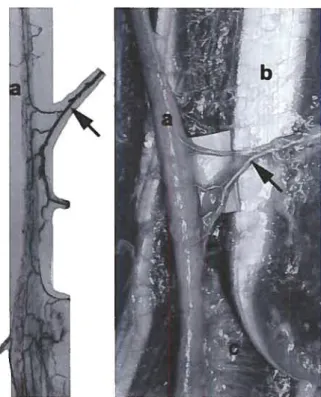
Fig. 1. Skin angiogram ofthe anterior trunk. Note the inferior epigastric artery fa) and a perforator from the deep inferior epi gastric artery (arrow).
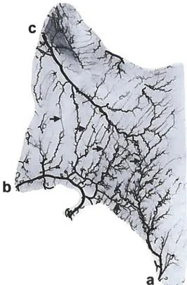
Fig. 2. Muscle angiogram ofthe externat oblique muscle. Note the intramuscular anastomotic connections (arrows) between the deep circumflex iliac (o), fourth lumbarartery(b), and twelfth intercostal(C)arteries.
Plastic and Reconstructive Surgery • May 2006
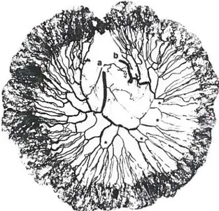
Fig. 5. Angiogram ofthe peritoneum of the right hemiabdo men, from the iliac crestto the costal margin (U, umbilicus). Note the contribution ofthe deep circumflex iliac artery (u) to the peri toneum in an “axial” pattern.
to prevent sedirnentation of the lead oxide. Rapid injection ofthe arterial system is undertaken until the characteristic patchy orange pattern is scen on the integuments, extremities, and conjunctiva. Once finished, Foley catheters are clamped. The average time required for injection is approxi mately 5 to 10 minutes. The average amount of lead oxide mixture injected is between 20 and 30 cc/kg, depending on the cadaver’s degree ofobe sity. Thinner bodies require less mixture per ki logram and obese bodies require more mixture per kilogram.
The skin is rinsed to rernove any deposits of lead oxide and the cadaver is placed in a freezer. Mter 48 hours, whole-body radiographs are taken to plan dissection. The body is then spiit in the appropriate planes and eviscerated while stiil frozen to prevent the spillage of contents of hollow organs. Angiograms are taken at every step to further define the vascular anatomy and variations encountered.
f”
I
a
Fig. 3. Bone angiogramofa fibula. Note the contribution ofthe peroneal arteryta) to the periosteum ofthe fibula (asterisks).
Fig.4. Small bowel angiogram. Note the vascular arcadestas terisks)betweentwobranches of the superior mesentericartery
Volume 117, Number 6 • Vascular Injection Techniques Angiograms are digitalized with a 5-megapixel
Nikon Coolpix 5000 camera (Nikon Corporation, Tokyo, Japan). Images are manipulated and as sembled to scale as required with Adobe Photo shop CS (Adobe Systems, Inc., San Jose, Calif.). Measurements and surface area calculations are performed with Scion Image Beta 4.02 (Scion Cor poration, Frederick, Md.). Typical angiograms can be seen in Figures 1 through 7.
Our modification of the lead oxide injection technique is a simple method for produce high quality angiograms. Three main problems with tra ditional injection methods have been addressed. First, a lead oxide suspension in gelatin with opti mal radiopacity and elasticity and a lower sedimen tation rate has been devised (Table 3). Second, pressure points from prolonged body storage are relieved by floating thebody inwamwater. Third, keeping the integument temperature above die melting point of gelatin during injectionallowsbet ter penetrance ofthe fine angiosomal networks of
/ \.r-T1
Fig.6. Angiogram of the quadriceps tendon and patellar liga ment. Note thevasculararcades atthejunction ofthe quadriceps
theinteguments. Our technique ailows us to obtain high-quality angiograms of integuments, muscles, bones, periosteum, tendons, nerves, viscera, and pesitoneum (Figs. 1 through 7).
Limitations of die method include the inabil ity to prevent bursting of small capillaries when excessive pressure is appiied during injection, in abiiity to reverse postmortem degradation of the vascular system, and inability to completely inject areas of unrecognized premortem pressure sores. Also, overfihling of the arterial system can iead to venous filiing, sometimes seen in the superficial venous system of the extremities. Lead oxide is aiso a toxic substance that requires the operator to wear a mask and gloves during manipulation. A special faciiity for disposai ofiead is also necessary.
This article provides a historical review of in jection techniques. Multiple injection techniques
Table 3. Lead Oxide Preparation
Ingredients Quanflty
300 Bloom gelatin 5 g
Fig. 7. Nerve angiogram ofthe median nerve. Note the intran eural course ofa branch ofthe radiaiartery(arrow) in the median nerve fa). Flexor poilicis longus(b);pronator quadratus(C).
Plastic and Reconstructive Surgery • May 2006
of interest to the plastic surgeon have been re viewed. The details provided in the article should allow the investigator to produce high-quality an giograms of the microcirculation that are neces sary for the study of perforator flaps.
Stevenf. Marris, M.D., M.Sc. Division of Plastic Surgeiy, Room 4443 1796 Summer Street Halifax, Nova Scotia B3H 3A7, Canada
1. Tang, M., Geddes, C. R., Yang, D., et al. Modified lead oxide gelatin injection technique for vascular studies. Chin.j Clin. Anat. 1: 73, 2002.
2. Paweletz, N. Birth of the life sciences in The Netherlands and Belgium. Nat. Rev. Mot. C’ett. Biot. 2: 857, 2001.
3. Whitten, M. B. A review of the technical methods of dam onstrating the circulation ofthe heart. Arch. Intern. Mcd. 42: 846, 1928.
4. Palmer,J. H., and Taylor, G. I. The vascular territodes ofthe anterior chest wall. Br. j PÏast. Swg. 39: 287, 1986. 5. Taylor, G. I., Townsend, P., and Corlett, R. Superiority of the
deep circumfiex iliac vessels as the supply for ftee groin [laps. PÏast. Reconstr. Surg.64: 595, 1979.
6. Stokes, R. B., Whetzel, T. P., Sommerhaug, E., et al. Arterial vascular anatomy of the umbilicus. PlasI. Reconstr. Surg. 102: 761, 1998.
7. Taylor, G. 1., and Palmer,J.H. The vascular territories (an giosomes) of die body: Experimental study and clinical ap plications. Br.j Plast. Surg. 40: 113, 1987.
8. Whetzel, T. P., and Lechtman, A. N. The gracilis myofascio cutaneous flap: Vascular anatomy and clinical application. Flast. Reconstr. Surg.99: 1642, 1997.
9. Gajisin, S., Bednarkiewicz, M., and Zbrodowski, A. Blood supply of the digital sheath. Chir. Main 17: 147, 1998. 10. Gajisin, S., and Zbrodowski, A. Local vascular contribution of
the superficial palmar arch. Acta Anat. (Baset) 147: 248, 1993. 11. Zbrodowski,A., Giimener, R., Gajisin, S., et al. Bloodsupply ofsubcutaneous tissue in the leg and its clinical application. Clin. Anat. 8: 202, 1995.
12. Zbrodowski, A., Mariethoz, E., Bednarkiewicz, M., et al. The blood supply of the lumbrical muscles.j Hand Surg. (Br.)23: 384, 1998.
13. Zenn, M. R., and Heitmann, C. Extended TRAM flap: Fea sibility study on fresh human cadavers. Ann. Plast. Surg. 50: 256, 2003.
14. Yousif, N.J.,Ye, Z., Grunert, B., et al. Analysis of the distri bution of cutaneous perforators in cutaneous flaps. Ptast. Reconstr. Surg. 101: 72, 1998.
15. Godat, D. M., Sanger,J. R., Lifchez, S. D., et al. Detailed neurovascular anatomy of the serrams anterior muscle: Im plications for a functional mtiscle [lap with multiple mdc-pendent force vectors. PlasI. &constr. Surg. 114: 21, 2004. 16. Spalteholz, W., and Hirsch, C. Coronararterien und Herz
mc,skel: Anatomische und experimentelle Untersuchungen. Dtsch. Med. Wochenschr. 1: 790, 1907.
17. Gelberman, R. H., and Mortensen, W. W. The arterial anat omy of the talus, foot Ankle 4: 64, 1983.
18. Handley, R. C., anti Pooley,J. The venous anatomy of the scaphoid. j Anat. 178: 115, 1991.
19. Fasol, P., Munk, P., and Strickner, M. Blood supply of the scaphoid bone ofthe hand. Acta Anat. Baset) 100: 27, 1978.
20. Geppert, M.J., Sobel, M., and Hannafin,J.A. Microvascu lature of the tibialis anterior tendon. Foot Anktc 14:261, 1993. 21. Sobel, M., Geppert, M.J., Hannafin,J., et al. Microvascular anatomy of die peroneal tendons. foot Ankle 13: 469, 1992. 22. Weinstabl, R., Wagner, M., Schabus, R., et al. Anatomical bases of patellar tendon grafts used in anterior cniciate lig ament reconstruction. $urg. Radial. Anat. 8: 163, 1986. 23. Mikic, Z. The blood supply of the human distal radioulnar
joint and the microvasculature of its articular disk. Clin. Orthop. 275: 19, 1992.
24. Koebke,J., Schafer, W., and Aust, T. Carpal tunnel topog raphy during endoscopie decompression. j Hand Surg. (Br.) 24: 3, 1999.
25. Mu, L., Yan, Y., Li, S., et al. Transparent morphology of the thoracoabdominal wall.j Reconstr. Microsurg. 17: 611, 2001. 26. Bemardes, A., Esperanca-Pina,J. A., Goyri O’Neill,J., et al. Diaphanization: Modifications of organ weight and volume
(in French). Bail. Assoc. Anal. (Nancy) 76: 53, 1992. 27. Steinke, H., and Wolff, W. A modified Spaltehoiz technique
with preservation of the histology. Ana. Anal. 183: 91, 2001. 28. Zhong, S. Z., Wang, G. Y., Yuan, L., et al. Anatomic basis of
venous drainage in donor flaps. Surg. Radial. Anat. 16: 349, 1994.
29. Crouzet, C., foumier, H., Papou, X., et al. Anatomy of the arterial vascularization ofthe lips. $urg. Radial. Anal. 20: 273, 1998.
30. Cheung, L. K The blood supply of the human temporalis muscle: A vascular corrosion cast study. I Anal. 189: 431, 1996.
31. Winters, H. A., Bouman, M. B., Boom, F., et al. The perito neal free fiap: An anatomic study. Plasl. Reconstr. Surg. 100: 1168, 1997.
32. Travers,V., Kanaujia, R. R., andlkuta,Y. Resin corrosion cast in experimental evaluation of femoral microanastomosis. Ann. Uiir. Main 6: 324, 1987.
33. Skinner, S. A., Tutton, P.J., and O’Brien, P. E. Microvascular architecture ofexperimental colon tumors in the rat. Cancer Res.50: 2411, 1990.
34. Walocha,J.A., Szczepanski, W., Miodonski, A.J., et al. Ap plication ofacrylic emulsion Liqtutex R (Binney and Smith) for the preparation of injection specimens and immtinohis tochemical studies: An observation. folia Morphol. (Warsz.) 62: 157, 2003.
35. Haschek, E., and Linderthal, O. T. Ein Beitrag zur praktis chen Venverthung der Photographie nach Rontgen. Wien Kiin. Wochenschr. 9: 63, 1896.
36. Ferguson, F. R. Roentgenological injection masses: Old and new. j Anal. 59: 297, 1924—25.
37. Dutto, U. Photographies du système artériel obtenues avec les rayons de Rôntgen. Arch. Ital. Biol. 25: 320, 1896. 38. Dutto, U. Fotografi del sistema arterioso ottenute con raggi
Rôntgen. &nctk fraie Acad. Lincei. 5: 129, 1896.
39. Braus, H. Uber Photogramme von Metallinjektionen mittels Rontgenstrahlen. Anat. Anz. 11: 625, 1896.
40. Gough,J. A. A method of injecting the blood-vessels for roentgenological studies and simtiltaneously embalming. Anal. Rec. 18: 193, 1920.
41. Baumgarten, W. lnfarction in tise heart. Arn.j Physiol. 2: 243, 1899.
42. Frank, O., and Alwens, W. Kreislaufstudien am rontgen schirm. Munch. Mcd. Wchenschr. 57: 950, 1910.
43. Jammn, F., and Merkel, H. Die Koronararterien des rnenschtichen Henens unlernonnaten undpathologischen Verhattnissen.Jena: G. Fisher, 1907.
44. Parker, G. H. Notes on Roentgen-ray injection masses. Anat. fer. 7: 247, 1913.
Volume 117, Number 6 • Vascular Injection Techniques 45. Hinman, F., Morison, D. M., and Lee-Brown, R K Methods of
demonso-ating die circulation in general.JA.M.A. 81: 177, 1923. 46. Cadenat, F. M. Endartérite oblitérante du tronc axillo-hu méral droit; repérage dii siège de l’oblitération par injection intra-artérielle de lipiodol. Butt. Mém. Nat. Soc. Chir. Paris 50: 1149, 1924.
47. Berberich, J., and Hirsch, S. Die roentgenographische Darstellung der Arterien und Venen am Lebenden. Munch. Kiin. Wochenschr. 49: 2226, 1923.
48. Salmon, M. Artères de la peau: étude anatomique et chirur gicale. Paris: Masson, 1936.
49. Salmon, M. Artères des muscles de la tête et du coti. Paris: Masson, 1936.
50. Schlesinger, M.J. An injection plus dissection study ofcoronaiy artelyocclusions and anastomoses. Am. Heartj 15: 528, 1938. 51. Schiesinger, M.J. New radiopaque mass for vascular injec
tion. Lab. Invest. 6: 1, 1957.
52. Olovson. Beitrag zur Kenntnis des Verbindungen zwischen a. iliaca interna und a. femoralis beim Menschen. Acta hir. Scanct. Suppl. 67, 1941.
53. Lindbom, A. Arteriosclerosis and arterial thrombosis in the lower limb: A roentgenological study. Acta Radiot. Suppi. 80: 1, 1950.
54. Tnteta,J., and Harrison, M. H. M. The normal vascular anatomy of die femoral head in aduit man.j Bonejoint Surg. (Br.) 35: 442, 1953.
55. Shehata, R. Radio-opaque modification ofKellner’s injection mass. Acta Anat. 87: 461, 1974.
56. Rees, M.J., and Taylor, G. I. A simplified lead oxide cadaver injection technique. Plast. Reconstr. Surg. 77: 141, 1986. 57. Tan, B. K., Ng, R. T. H., Tay, N. S., et al. Tissue microan
giography using a simplified baritim sitiphate cadaver in jection technique. Ann. Acad. Mcd. Singapore28: 152, 1999. 58. Quinodoz, P., Quinodoz, M., Nussbaum,J., et al. Baiium sctlphate and soft-tissue radiology: Mlying the nid and the new for the investigation of animal cutaneous microcircula tion. Br. j Ftast. Surg. 55: 664, 2002.
59. Jamin, f., and Merkel, H. Stereoscopic skiagrams of the coronary arteries of the human heart under normal and pathological conditions (Abstract). Arch. Roentg. Ray 11:328, 1906—07.
60. Houseman, N. D., Tayior, G. I., and Pan, W. R. The angio somes of the head and neck: Anatomie study and clinical applications. Ftast. Reconstr. Surg. 105: 2287, 2000. 61. Taylor, G. I. New approach to vasctilar injection in fresh
cadaver dissection (Discussion). J. &constr. Microsurg. 20: 457, 2004.
62. Burgio, L., Clark, R.J., and Firth, S. Raman spectroscopy as a means for the identification ofplattnerite (Pb02), oflead pigments and of their degradation products. Anatyst 126: 222, 2001.
2.6.3 Comparison of different investigation methods
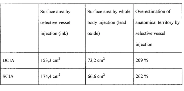
OÏder anatomical investigation techniques relied on the selective injection of bÏood vessels with either ink6 or radiopaque material99. It is though that selective injection ofblood vessels could overestimate the actual anatomical territory ofa given vesse! since the injectate overflows in adjacent territories via choke vesse!s’°°’1°1. However, there is no objective information on this topic in the !iterature, which could be usefiti in comparing our results with earlier studies.
2.7
Literature review summary
The DCIA osteocutaneous flap with itiac crest has been one ofthe major fiaps used for mandibular reconstruction since its description in I97956• is known for the large amount of vascularized bone available, the similarity in shape between the iliac crest and the mandible, and its vascular pedicle length and size.
Anatomical research bas allowed precise characterisation of various flap
components and improvements over the original flap design have been achieved. The inner cortex ofthe iliac crest is mainly supplied by the DCIA through
periosteal circulation6. This allows the longitudinal spiitting ofthe crest8’9 to reduce flap bulk and diminish donor site morbidity. The iliac crest can also be
osteotomized to beller fit the jaw contour as long as its the periosteum is left intact’0 Others have characterized the contribution of the DCIA to the interna! oblique muscle”, which has been used to facilitate closure ofthrough and through osteomucocutaneous defects ofthe
The soft-tissue component of the DCIA flap however, bas received littie attention. Two major problems have halted the development and usage ofthe DCIA osteomusculocutaneous flap for mandibular reconstruction: the unnecessary bulk brought by the “obligatory muscle cuf?’ 13-15and the tethering ofthe skin to the bone which renders soft tissue placement problematïc in complex oromandibular reconstructions13’5. Rapid developments in the field of perforator flap surgery could help solve this problem.
Current anatomical descriptions of the DCIA perforators5’6’13 are conflicting. Pioneering efforts by Safak’3 and Kimata’4”5 at designing a DCIA perforator flaps bave had limited success and retiabitity ofthe DCIA perforators bas been
questioned. The exact number and location ofperforators, and skin territory ofthe DCIAP remains unclear.
3
Research questions and hypothesis
Our main research question is: “Is it possible to reliably design and use a DCIA osteocutaneous perforator flap?” To answer this question, three specific questions need to be answered:
• Are there consistent DCIA perforators?
• Do DCIA perforators have common characteristics?
• Do these characteristics allow the dissection ofa DCIA osteocutaneous perforator flap?
The research objectives ofthis thesis are thus:
• To clarify the presence or absence of DCIA perforators.
• To determine a common set ofcharacteristics for the DCIA perforators
• To dernonstrate the vascularization of a DCIA osteocutaneous perforator flap.
We hypothesize that it is possible to establish the anatomical basis ofa DCIÀ osteocutaneous perforator flap. This section expands on measurements necessary to answer the research questionsand states the research hypotheses.
3.1
Are there DCIA perforators?
The existence of DCIA perforators is assessed throughtwovariables: the presence or absence ofperforators, and the number ofperforators. Measures: identification and counting ofeach cutaneous perforators from the DCIA in the tumbar region with the help of angiography and photography. Presence ofDCIA perforator(s) in at Ieast 80% ofspecimen is adequate. This number is generally accepted in clinicat practice to say that the vascular anatomy ofa fiap is reliable.
Hypothesis 1
32
Do DCIA perforators have common
characteristics?
The DCIA perforators characteristics pertinent to this research relate to the number of perforators, the perforator diameter, the distance to iliac crest, the distance from ASIS, the pedicle length to deep fascia, the angiosome surface, and the “perforator zone” surface. Measures: Average number of perforators, mean perforator diameter, shortest distance to iliac crest, distance from ASIS, pedicle length to deep fascia, angiosorne surface, “perforator zone” surface.
Hypothesis 2
DCIA perforators have a set of common characteristics that allows their clinical location.
3.3
Do these DCIA perforators charactenstîcs allow
the dissection ofa DCIA perforator flap?
The possibility to dissect a DCIA perforator flap is assessed through five criteria: the perforator diameter, the location ofperforators, the cutaneous territory stipp lied by the perforator, the identification of the perforator, and the integrity of the vascularization. These criteria are presented wïth the corresponding measures.
1) Perforator diameter
The cutoffsize is set at >O,5mm since the microanastomosis of vesse! smaÏler than O,5mm is nearly impossible in current clinica! practice. Also, Dopplers commonly used to map pre-operative!y perforators cannot easi!y detect vessels smaller than O,5rnm. Internai diameter bas been chosen as it is the most accurate method to measure vesse! diameters with the !ead oxide technique.
2) Location of perforators
The location ofthe perforator must be precisely described.
Measure: Distance from anatomica! landmarks (iliac crest and ASIS).
3) Cutaneous territory
Each perforator should supply an adequate skin region.
Measure : Average perforator zone. Set at 22cm2, this is the average perforator zone of musculocutaneous perforators, as reported by Cormack and Lamberty’°2.
4) Discriminant and confluent identification ofthe perforator during dissection
a) Discriminating measure. During dissection, the DCIAP should be distinguishab!e from other perforators in the area.