HAL Id: hal-03039545
https://hal.inria.fr/hal-03039545
Submitted on 3 Dec 2020
HAL is a multi-disciplinary open access
archive for the deposit and dissemination of
sci-entific research documents, whether they are
pub-lished or not. The documents may come from
teaching and research institutions in France or
abroad, or from public or private research centers.
L’archive ouverte pluridisciplinaire HAL, est
destinée au dépôt et à la diffusion de documents
scientifiques de niveau recherche, publiés ou non,
émanant des établissements d’enseignement et de
recherche français ou étrangers, des laboratoires
publics ou privés.
Multiple Permanent Faults Mitigation Through
Bit-Shuffling for Network-on-Chip Architecture
Romain Mercier, Cédric Killian, Angeliki Kritikakou, Youri Helen, Daniel
Chillet
To cite this version:
Romain Mercier, Cédric Killian, Angeliki Kritikakou, Youri Helen, Daniel Chillet. Multiple
Perma-nent Faults Mitigation Through Bit-Shuffling for Network-on-Chip Architecture. ICCD 2020 - IEEE
International Conference on Computer Design, Oct 2020, Hartford / Virtual, United States. pp.1-8.
�hal-03039545�
Multiple Permanent Faults Mitigation Through
Bit-Shuffling for Network-on-Chip Architecture
Romain Mercier
Univ Rennes, Inria, CNRS, IRISA Lannion, France
C´edric Killian
Univ Rennes, Inria, CNRS, IRISA Lannion, France
Angeliki Kritikakou
Univ Rennes, Inria, CNRS, IRISA Rennes, France [email protected]
Youri Helen
DGA MI Rennes, France [email protected]Daniel Chillet
Univ Rennes, Inria, CNRS, IRISA Lannion, France
Abstract—Since several decades, fault tolerance has become a major research field, due to transistor shrinking and core number increasing in System-on-Chip (SoC). Especially, faults occurring at the Network-on-Chips (NoCs) of those systems have a significant impact, since NoCs are the key component of on-chip communication. Several fault tolerant approaches have been proposed, which are, however, limited against multiple permanent faults. To reduce the impact of these faults on the data communications, we propose a bit-shuffling method for fault tolerant NoCs. The proposed approach exploits, at run-time, the position of the permanent faults and changes the order of bits inside a flit. Our bit-shuffling method reduces as much as possible the fault impact, by transferring the faults from Most Significant Bits (MSBs) towards Least Significant Bits (LSBs). With this technique, we show that, in presence of multiple permanent faults, the Mean Square Error (MSE) on the payload
transmission is reduce from 1017to 105 under three permanent
fault for 32-bit unsigned integers. This technique also ensures the correct transmission of headers under multiple permanent faults.
Index Terms—Network-on-Chip, Fault Mitigation, Approxi-mate Computing, Bit-Shuffling
I. INTRODUCTION
Due to increasing chip density, platforms are developed with large number of processing elements, i.e. cores, on a single System-on-Chip (SoC). However, conventional commu-nication means, such as buses and point-to-point links, cannot ensure efficient communication on these multicore and many-core platforms. To address this gap, Network-on-Chip (NoC) appeared as a scalable solution to manage communications between a large number of cores [1].
Meanwhile, the technology scaling and the transistor density increase enabled voltage reduction. As a result, the intrinsic failure rate of electronics, due to gate oxide breakdown, is increased [2]. Moreover, as the transistor size reaches 10 nm and below [3], the engraving thinness causes more and more hardware defects, due to manufacturing process, creating permanent faults that affect the reliability of devices [4]. During system operation, electromigration and time-dependent dielectric breakdown become additional sources of permanent
faults on devices [5]. In this technology era, interconnects and routers of NoC became more sensitive to permanent faults [6], affecting their functionality.
Fault tolerance techniques are commonly applied on the NoC [7] to deal with permanent faults. They are usually based on i) mitigation through routing algorithms [8], ii) reconfig-uration [7], iii) correction through circuit replication [4] and iv) information redundancy [9]. Although the aforementioned approaches are efficient for single permanent fault, they are less adequate for multiple permanent faults. They introduce high costs, in terms of latency, area and power consumption, while their mitigation capabilities are limited, as discussed in Section II.
To efficiently deal with multiple permanent faults, we pro-pose a bit-shuffling hardware technique with low area and performance overhead. The proposed technique focuses on reducing the impact of faults, instead of fully mitigating them. It ensures the protection of Most Significant Bits (MSBs) of the data, by transferring the impact of the permanent faults to the Least Significant Bits (LSBs), instead of the MSBs. This is achieved by dividing a flit into several blocks of bits, named Sub-Flits (SFs), and by exchanging (shuffling) the position of the SFs, at run-time. Following the proposed approach, spatial redundancy is not required, thus the area overhead is reduced, while faulty routers are not excluded, removing the negative impact in terms of performance. Moreover, the pro-posed technique can reduce the impact of multiple permanent faults, according to the accuracy needed by the application executed on the NoC based architecture. As a result, it is especially suitable for several application domains, such as image processing, data mining, machine learning, information gathering, etc., where approximate data are tolerated, both for computations and for communications [10].
The rest of this paper is organized as follows. Section II presents the related work on fault tolerant NoC. The proposed bit-shuffling technique is presented in Section III. Section IV presents the experimental results. Finally, we conclude this study and we present our future work in Section V.
II. RELATEDWORK
Fault tolerant techniques for NoCs can be grouped into four main categories, described in the following paragraphs.
Routing algorithms are used to avoid faulty paths or faulty regions in NoCs [8]. For instance, only the remaining healthy resources of NoCs are used during transmission [11]. These algorithms are generally table-based [11], including rules to avoid congestion and deadlock during packet transmissions. Therefore, as the NoC size increases, the hardware cost drastically increases. Using routing algorithms is efficient, as long as the number of faults is limited. Otherwise, the latency may become higher than the acceptable limit, and thus, some Intellectual Properties (IPs) become unreachable. Therefore, this solution is less suitable for large NoCs and multiple faults. Reconfiguration replaces a faulty element of the NoC by using spare resources at different levels [12]. As spare re-sources can be used only once, these techniques have large overhead in terms of area and power consumption, while they can tolerate few faults. Other reconfiguration approaches use default-backup paths to avoid data corruptions and packet re-transmissions [13]. Although default-backup paths have low area and power consumption, the latency drastically increases under multiple faults, due to the routing complexity. In the worst case, several IPs become unreachable.
Circuit replication, called N-Modular Redundancy (N-MR), replicates N times, fully or partially, the architecture and votes the replicated outputs. The most popular approach is Triple Modular Redundancy (TMR) [4], where a module is replicated three times. To reduce hardware cost, the voter circuit is excluded from transistor triplication [14] and the circuit parts, to be triplicated, are isolated [15]. Multiple faults are masked if they occur in the same module. However, if more than one module is affected, the voter cannot correct the output. The overhead in terms of area and power consumption stays significantly high, e.g., more than three times for TMR.
Information redundancy inserts additional bits inside mes-sages using Error-Correcting Codes (ECCs). The most com-monly used coding scheme for NoC is the Hamming code, which can detect two faulty bits but can correct only one. Despite the increase of the bus size of the complete NoC, Hamming code is efficient for correcting single faults [9]. To increase the number of correctable faulty bits, the message is encoded on two dimensions [16]. However, using ECCs to correct more than one faulty bit dramatically increases the area overhead [17]. As a result, the application of ECC approaches is limited against multiple faults.
Last but not the least, approximate computing approaches have been proposed in several research fields, with a similar idea of transferring the impact of faults towards LSBs, through bit-shuffling. In telecommunication, interleaving methods manage burst errors by spreading the errors across several packets. However, they are limited to serial transmissions [18]. In NoCs, data are forwarded through buses and permanent faults impact every flit that crosses a faulty bus or router. Since faults always appear in the same positions in each
flit, the application of interleaving methods is limited in this context. In memory, bit-shuffling methods, called scrambling, are used to prevent memories from faults and increase their lifetime [19].
Contrary to the aforementioned approaches, our work effi-ciently addresses the mitigation of multiple permanent faults for data transferred through the NoC, based on a low overhead hardware mechanism.
III. PROPOSEDBIT-SHUFFLINGTECHNIQUE This section presents the proposed bit-shuffling method, which tackles the impact of multiple permanent faults on the data traversing the NoC. This is achieved by re-organizing the data bits to allocate LSBs on faulty locations.
A. Target domain and assumptions
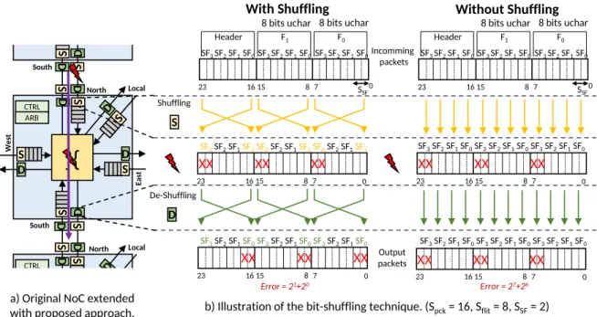
The proposed approach focuses on multiple permanent faults that are located in i) the interconnection between routers, and in ii) the buffers and the crossbar within the routers, as illustrated by the red lightnings in Fig. 1-(a). In the context of data transferred on NoCs, multiple permanent faults can appear as several Single Bit Upsets (SBUs) and Multiple Bit Upsets (MBUs) [20]. While SBUs are composed by several Single Event Upsets (SEUs), which affects several bits in the same flit, MBUs are induced by a single SEU which affects several adjacent bits of the same flit. With nanoscale tech-nologies and power scaling, devices become more susceptible to multiple permanent faults [21]. As buffers and crossbar are the biggest components of a router, they have higher probability of accumulating faults due to radiation effects, manufacturing defects or other intrinsic failures. For the same reasons, interconnections are often impacted by permanent faults, usually stuck-at or bridge type faults.
This work does not focus on fault detection. We assume that the positions of the faults are provided by methods such as Built-In Self-Test (BIST) techniques [12], which diagnose faults in interconnections and routers using Test Pattern Gen-erator (TPG) and Output Response Analyzer (ORA) blocks. In this techniques, TPGs send test packets through the NoC, while ORAs analyze the received packets to deduce if faults occurred between these two blocks, providing their positions and the fault type. As these techniques are largely studied in the literature, they are not detailed in this paper. Further details can be found in [22].
As the objective of the proposed approach is to reduce the impact of multiple faults, instead of correcting them, the targeted domains consist of error resilient applications, i.e. applications which can tolerate errors until a certain level, such as image processing and machine learning [10].
B. Bit-shuffling principle
We consider classic NoC routing messages of Smsg bits.
Fig. 2 illustrates the organization of such a message into packets and flits. A message is decomposed into NP packets
of Spck payload bits, each packet contains NF flits of Sf lit
8 bits uchar 0 1615 8 7 23 F0 F1 Header 8 bits uchar 0 1615 8 7 23 0 1615 8 7 23 SSF SF0 SF1 SF2 SF3 SF0 SF1 SF2 SF3 SF0 SF1 SF2 SF3 SF0 SF1 SF2 SF3 SF0 SF1 SF2 SF3 SF0 SF1 SF2 SF3 SF3 SF1 SF2 SF0 SF3 SF1 SF2 SF0 SF3 SF1 SF2 SF0 Shuffling De-Shuffling Error = 21+20 X X X X X X X X X X X X D S CTRL North Ea st Local South W es t S D S D ARB South S D CTRL North Local ARB S D
}{
S S D D S D S D S S D D 8 bits uchar 0 1615 8 7 23 F0 F1 Header 8 bits uchar 0 1615 8 7 23 SSF SF0 SF1 SF2 SF3 SF0 SF1 SF2 SF3 SF0 SF1 SF2 SF3 SF0 SF1 SF2 SF3 SF0 SF1 SF2 SF3 SF0 SF1 SF2 SF3 Incomming packets X X X X X X Output packets 0 1615 8 7 23 Error = 27+26 X X XX X X SF0 SF1 SF2 SF3 SF0 SF1 SF2 SF3 SF0 SF1 SF2 SF3a) Original NoC extended
with proposed approach. b) Illustration of the bit-shuffling technique. (Spck= 16, Sflit= 8, SSF= 2)
With Shuffling Without Shuffling
Fig. 1: Illustration of the bit-shuffling technique through an extended original NoC.
Smsg-1 Message SF0 SFn-1 Pi PNp-1 … Flit0 Flit1 FlitNf-1
Header Packets and Flits
SF0 SF0 SFNsf-1 SFNsf-1 Smsg Sflit Sflit P0 Flit0 Flit1 FlitNf-1 Header Sub-Flits (SFs) Sflit Sflit SSF … … … … … … … … … … … … … … … … … … … …
Legend: Payload Control
Header
Fig. 2: Message formatting into packets, flits and sub-flits.
Symbol Definition Symbol Definition
Smsg Message size NP =
Smsg
Spck Number of packets
Spck Payload size NF =
Spck
Sf lit Number of flits
Sf lit Size of a flit NSF =
Sf lit
SSF Number of sub-flits
SSF Size of a sub-flit
TABLE I: Notation summary.
As depicted in Fig. 2, we further decompose each flit into NSF Sub-Flits (SF) of SSF bit size to enable the proposed
bit-shuffling technique. Table I summarizes the notation. The proposed method applies shuffle and de-shuffle func-tions that switch, at run-time, two or more SFs within the same flit, in order to move the impact of errors on LSBs. Fig. 1 illustrates through an example the principles of our approach. Let’s consider flits crossing a faulty router from north to south, as shows the purple arrow of Fig. 1-(a). For simplification reasons, the illustration example considers a single buffer, but
the proposed approach is also applicable with virtual channels. The example focuses on payload flits, while header flits are discussed in Section III-D2. As depicted in Fig 1-(b), we consider Sf lit = 8 bits and a SF size equal to SSF = 2.
Therefore, the number of SFs (NSF) in a flit is equal to
NSF = 4 (SF0 to SF3). When no faults occur, the shuffle
and de-shuffle functions are disabled and each flit crosses the NoC router without modification.
Let consider now that two permanent faults occur in the input buffer, affecting the MSBs, i.e., bits 7 and 6 of all incoming flits. The right part of the Fig 1-(b) illustrates the crossing of packets without the proposed bit-shuffling method. The bits 7 and 6 of the two payload flits are affected, leading to errors included in the range {0, +64, +128, +192}, depending on the initial value of the affected bits. The left part of the Fig 1-(b) illustrates the proposed shuffling method. The bit-shuffling technique is enabled in the input ports of the router, before crossing the faulty path. The SFs are re-organised by placing the LSBs on the faulty positions, i.e. SF0 and SF3
are swapped inside each flit. As a result, the impact of the permanent faults in terms of absolute error for the payload part is reduced to the range {0, +1, +2, +3} according to the bit values of the LSBs. Before the flit leaves the NoC router, the SFs are brought back in their initial position, and then, the flit is sent to the output port.
C. Method implementation
1) Hardware architecture: To implement the proposed ap-proach, a classic NoC router is extended with extra hardware blocks: Shuffle (S) and De-shuffle (D) blocks. The goal of the shuffle block is to re-organize the SFs with the objective of minimizing the impact of the faults. The goal of the De-shuffle block is to bring back the initial order of the SFs. To deal with the targeted faults, the bit-shuffling method is applied i) between two routers to mitigate errors on the interconnection
bus, and ii) between the input and output ports to mitigate errors inside the router. To achieve that, the aforementioned paths integrate S and D hardware blocks, as depicted in Fig. 1-(a).
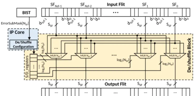
The S and D blocks have the same hardware architecture which is presented in Fig. 3. It is composed of NSF simple
multiplexers (SSF-to-1) and registers, which contain the
con-figuration of the multiplexers. The only difference between S and D blocks, is the value of the registers that configures the MUXs. These values are named S registers and D registers for a S and D block, respectively. Their values are computed by the IP core associated to the router. It takes as input the position of the permanent faults, which is the output of BIST techniques. The BIST is classic, efficient, localization and fault characterization technique, detailed in [12].
2) Shuffle and Deshuffle registers computation: The com-putation of the register values applied to the MUXs of the shuffle and deshuffle blocks is done by the sorting algorithm presented in Algorithm 1. This algorithm is similar to bubble sort [23]. Its aim is to compute the bit-shuffling configuration that minimizes the impact of faults in order to configure the registers that control the multiplexers. The algorithm is executed on the dedicated IP core of the router based on the BIST results (position of the faults). This algorithm takes as input a mask of error position, having the same size as the databus of the considered NoC. Each bit of this error position mask defines the state of the datapath bit-line: a ’0’ indicates that the path of the bit is fault-free and a ’1’ indicates that the path of the bit is faulty. For sake of clarity, we organize the error position mask bits in NSF groups of SSF bits, which are
named SubM ask in Algorithm 1. In this way, each SubM ask gives the fault impact value of the associated subflit. For example, if we consider a 16-bit datapath with 4-bit subflits, where bits 6, 7 and 13 are faulty, we have an error position mask = [0010, 0000, 1100, 0000] that gives SubM ask[0] = 0, SubM ask[1] = 12, SubM ask[2] = 0, and SubM ask[3] = 2. In lines 1 − 5 of the Algorithm 1, the variables and registers are initialized. Each register is set with the value of its position (S register = [3, 2, 1, 0]), hence the data cross the block without modification.
In lines 7 − 16, a bubble sort algorithm computes the values of the deshuffling register, according to the input SubM ask[NSF]. For that, the sort algorithm orders the
SubM ask values in a decreasing order and applies the same ordering on the table D register. For example, if SubM ask[1] is inferior to SubM ask[2], the two values are swapped, and the values D register[1] and D register[2] are also swapped. When the computation is over, the deshuffling register contains the multiplexer configuration D register[NSF] for the architecture presented in Fig. 3. In
this way, the i-th value of the register indicates which input subflit is set into the i-th output subflit.
Finally, as the hardware architectures of a S and D blocks are similar, the shuffling register is simply computed from the deshuffling one, as shown from lines 18 to 20.
log2(NSF) Input Flit … … … … … SFNsf-2 SF1 SF0 SFNsf-1 … … … … … Output Flit … … … … …
MUX NSF:1 MUX NSF:1 MUX NSF:1 MUX NSF:1
SSF SSF SSF SSF SSF SSF SSF SSF S/D_ re gis te rs … … log2(NSF) lo g2 (NSF ) lo g2 (NSF ) De/s h u ffle B lo ck BIST De/Shuffle Configuration IP Core ErrorSubMask[NSF]
Fig. 3: Hardware architecture of shuffle (S) and deshuffle (D) blocks.
Input: SubM ask[NSF]
Output: S register[NSF], D register[NSF]
1: // Variable Initializations
2: reset register(S register)
3: reset register(D register)
4: inversion ← T RU E
5: // Deshuffling Register Computation
6: for ((i = 0 to NSF− 2) && (inversion)) do
7: inversion ← F ALSE
8: for (j = 0 to NSF− 2 − i) do
9: if (SubM ask[j] < SubM ask[j + 1]) then
10: swap(SubM ask[j], SubM ask[j + 1])
11: swap(D register[j], D register[j + 1])
12: inversion ← T RU E
13: end if
14: end for
15: end for
16: // Shuffling Register Computation 17: for (i = 0 to NSF − 1) do
18: S register[D register[i]] ← i
19: end for
20: return S register[NSF], D register[NSF]
Algorithm 1: Shuffling/deshuffling registers update
D. Packet organization
To efficiently protect the communication with the proposed method, the following packet organization has to be consid-ered. However, as packet organization is always included in common NoC through the Network-interface (NI), which is the link between an IP core and a router, the proposed method does not require extra hardware.
1) Data Organization: The implementation of the proposed method must take into account the data size (Sdata) and the flit
size (Sf lit) to organize the flits inside the Network Interfaces
(NIs) of the NoC. For sake of clarity, we define as Most Significant Subflit (MSS) the SF including the MSB of the flit, and Low Significant Subflit (LSS) the SF including the LSB of the flit. Considering different data sizes, three cases, illustrated in Fig. 4, can occur:
a) Sdata = Sf lit, this is the straightforward case, since the
data are placed inside the flits without any reorganization, as show in Fig. 4a. The LSBs of the data are placed on the LSSs, and the MSBs of the data are placed on the MSSs. b) Sdata < Sf lit, more than one data is sent in one flit.
MSB LSB MSS LSS 32-bit data 32-bit flit SF3 SF2 SF1 SF0 SF3 SF2 SF1 SF0
(a) Data equal to flit size
MSS LSS 32-bit flit MSB LSB 16-bit data MSB LSB 16-bit data SF00 SF01 SF10 SF11 SF11 SF01 SF00 SF10
(b) Data smaller than flit size
MSS LSS 32-bit flit SF4 SF6 SF2 SF0 MSS LSS 32-bit flit SF5 SF7 SF3 SF1 … MSS LSS 64-bit data SF0 SF7 SF6 SF1
(c) Data larger than flit size Fig. 4: Flit organization illustrations 32-bit flit for different data sizes.
Hence, the data are interleaved within the flit, as shown in Fig. 4b: the MSBs of the data are grouped inside the MSSs, and the LSBs of the data are placed in the LSSs. c) Sdata > Sf lit, a data is sent on several flits. The LSBs
and MSBs of the data are equally distributed on the flits, as illustrated in Fig. 4c.
With this organization, the MSS always hold the important data, compared to the LSSs, making efficient the bit-shuffling method, even when the datapath is impacted by multiple permanent faults.
2) Header Protection: Header flits consist of control data, and these data contain in particular information for the packet routing. Hence, errors cannot be tolerated in these flits. To handle that, the proposed approach is extended as follows: For NoCs using large data buses (i.e. 64 bits), header flits usually include several unused bits, which are placed on the LSBs. When faults occur on the MSBs, inducing faulty routing, our bit-shuffling method transfers the faults on the unused SFs, ensuring a correct control of the flit. However, header flits with small data buses (i.e. 16 bits) do not usually include enough unused bits, and another solution must be included to ensure correct routing. To address this, the header flit is divided into two flits, which artificially inserts unused bits. Hence, half of the new header flits can be used to tolerate errors, with a small impact on the NoC latency, i.e. adding only one flit in a packet.
IV. EXPERIMENTALRESULTS
In this section, we compare the behavior of the proposed ap-proach with state-of-the-art apap-proaches. Section IV-A presents the evaluation of payload and header protections under multi-ple faults. Then, the proposed approach is validated with two benchmarks: i) Sobel filter and ii) k-mean clustering algorithm in Section IV-B. Finally, Section IV-C presents the hardware implementation costs.
A. Packet Level Simulations
1) Payload mitigation: We evaluate the robustness of the proposed method considering random 32-bit payload flits, which contain 32-bit unsigned integer data organized into 4-bit subflits. As we focus on approximate applications, payload flits can tolerate data approximation up to a certain level. Therefore, we used the Mean Square Error (MSE) metric to quantify the impact of faults, considering each possible fault position on the payload flit. Fig. 5 compares the results of i)
the proposed approach (shuffled), with ii) flits protected with Hamming code and iii) unprotected flits. In this figure, we can observe that for one permanent fault, Hamming code is able to correct the data which means that the MSE is equal to zero while the shuffling method reduces the MSE from 1.9 × 10¹⁷ to 2.1 × 101. However, when more than one permanent faults are present, the Hamming code is not able to correct faulty bits and can even make false correction. In this case, the MSE obtained with the Hamming code is approximately equal to the MSE obtained when no protection is used, while the bit-shuffling method drastically reduces the MSE. For example, when three permanent faults are present, the MSE is reduced from around 6×10¹⁷(Hamming and unprotected) to 2.2×10⁵
with bit-shuffling.
1 2 3 4 5
Fault number per flit
100 103 106 109 1012 1015 1018
Me
an
Sq
ua
re
Err
or
(M
SE
)
Shuffled Hamming Unprotected Fig. 5: Payload flit accuracy.2) Header Protection: Regarding the protection of header transmissions, which cannot tolerate any corruption, we an-alyze the percentage of correct header transmissions (i.e. no control bits are faulty) in function of the number of permanent faults, in Fig. 6. We consider different methods for this evaluation: i) unduplicated and unprotected (U/U), ii) unduplicated and with Hamming code (U/H), iii) unduplicated and shuffled (U/S), iv) duplicated and unprotected (D/U), v) duplicated and with Hamming code (D/H), and vi) duplicated and shuffled (D/S) headers.
Fig. 6a presents the percentage of correct transmissions for a 64-bit header flit that contains 32 control bits, i.e. there is 32 unused bits in the header. In this case, header duplication is unnecessary until 5 faults per header, while the Hamming code ensures the correct header transmission when only one fault occurs. In Fig. 6b, a 32-bit header flit which contains 32
control bits is considered, i.e. there is no unused bits in the header. In this case, header duplication is necessary to achieve 100% of correct header transmissions up to 3 faults against 0 fault without header duplication. In both cases, the Hamming code is able to manage only one fault per header. Furthermore, we observe that applying shuffling to the header flit can assign unused bits on multiple permanent faulty bits (equal to the number of unused bits in one header). For large databus, the header duplication is not required to manage fault(s) with the bit-shuffling technique. However, when a small data bus is used, header duplication is useful, as shown in Fig. 6b.
Notice that, today’s NoC are typically based on large bus i.e. 64 bits. Hence, the duplication of headers is a solution that requires to be applied only in specific conditions, as the shuffling technique is sufficient by itself.
1 2 3 4 5
Fault number per header
0 20 40 60 80 100
Co
rre
ct
he
ad
er
tra
nsm
issi
on
(%
)
U/U U/H U/S D/U D/H D/S(a) 64-bit flit size
1 2 3 4 5
Fault number per header
0 20 40 60 80 100
Co
rre
ct
he
ad
er
tra
nsm
issi
on
(%
)
U/U U/H U/S D/U D/H D/S(b) 32-bit flit size. Fig. 6: Header flit accuracy. B. Application Level Evaluations
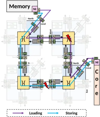
1) Experimental Setup: For the rest of the experiments, we consider data exchanges between a main memory and a core, located in a distance of 2-hops of a large mesh NoC, as illustrated in Fig.7. A XY routing algorithm is used to transmit data through the NoC, with 32-bit flit size, composed of 4-bit SFs. Hence, each flit has 8 SFs. The purple arrow depicts the routing path from memory to core for the load operation. The blue arrow is the routing path from the core to the memory for the store operation. The proposed bit-shuffling method is implemented through the S and D blocks to mitigate
permanent faults inside routers and interconnections. The red flashes represent faults on the data path, impacting flits. We consider: i) one 3-bit Multiple Cell Upsets (MCUs) permanent fault on the loading path (bits 27, 28 and 29) with stuck-at one fault model, and ii) two 2-bit MCUs permanent faults on the storing path (bits 7, 8 and 24, 25) with stuck-at zero fault model. CTRL North Ea st Local South W est S D ARB D S D S CTRL Ea st W est S D ARB S D D S S D S D S D D S S D Local North S D CTRL North Ea st Local South W est S D S D ARB D S D S CTRL Ea st W est S S D ARB S D D S S D S D S D
}{
S D}{
S D Local North D S D South D S South D S S D S D}{
S D D S}{
Memory
NI S DC
o
r
e
NI S D Loading StoringFig. 7: Localisation of faults on the load and the store paths for the two benchmarks deployed on a part of large mesh NoC. 2) Sobel Filter: For the first experiment, we simulate the execution of a Sobel filter, used for edge detection in image processing. Initial and output images are stored in the memory, shown at the top of Fig. 7. During load operations, 8-bit data (unsigned integer) transit the NoC through the purple path. During store operations, 64-bit data (double precision) transit the NoC through the blue path. As the flit size of the NoC is 32 bits, data are organized within flits, as described in Section III-D1.
To evaluate our approach, the Peak Signal-to-Noise Ratio (PSNR) is computed based on the fault-free reference. We compare the results of the Sober filter with the proposed bit-shuffling approach, the Hamming code approach and without any fault-tolerant technique. Fig. 8a shows the result obtained without any fault injection, i.e., the fault-free reference. Fig. 8b shows the result of the Sobel filter without any fault-tolerant technique. We observe that the edges intensities are drastically reduced, due to the stuck-at zero faults occurring at the store path. Moreover, stuck-at one faults on the load path induce anomalies in the original image, which are detected by the gradient computation of Sobel filter. Hence, noisy edges (not present in the fault-free reference) appear. According to these defects, the PSNR metric is equal to 13.07. On the contrary, when the bit-shuffling method is applied, the impact of faults
can be significantly reduced, as shown in Fig. 8c. In this case, the obtained image is very close to the reference image, despite the existence of faults. Indeed, our method achieves a PSNR equal to 34.58, which represents a gain of a factor of 2.5. Fig. 8d presents the Sobel result obtained when an Hamming code is applied. We can observe that the obtained result is worse than the result without any fault-tolerant method. This result is due to the fact that Hamming code cannot correct more than one fault and detect more than two faults in the same flit. Moreover, when multiple faults occur, false correction can be done which false the result. In this case, the computation of the PSNR gives no result considering the divergence of the result compared to the reference.
3) K-Means Clustering Algorithm: For the second experi-ment, we simulate the K-means clustering algorithm, typically used in signal processing and data mining, e.g., image classifi-cation and voice identificlassifi-cation. The algorithm’s input is a set of random data to be clustered, by minimizing the square distance between centroids and their data, through an iterative process. Experiments are simulated with a C++ testbench, using 32-bit signed fixed-point data with 1 bit for the integer part. We use 20 data sets composed of 15 centroids and 1000 sample data are generated by centroids. The number of iterations for each data set is limited to 150.
To evaluate the results, the MSE of the centroid positions and the Clustering Error Rate (CER) are computed. Fig. 9 depicts the results for the first data set. The fault-free result is given in Fig. 9a and it is used as reference for MSE and CER computation. Fig. 9b depicts the obtained output under faults, without fault-tolerant method. In this case, the K-mean algorithm cannot perform clusters, due to the square distance computation, which is totally distorted by the presence of the permanent faults on the load and store paths. On the contrary, the proposed bit-shuffling method enables a correct clustering, which is visually very close to the reference, as shown on Fig. 9c. To further evaluate our approach, we compare the MSE and CER considering all 20 data sets. The bit-shuffling method, under permanent faults, reduces the mean centroid positions MSE from 1.45 × 10⁻²to 7.47 × 10⁻⁸and the CER from 92.83% to 0.09%, compared to the version without fault-tolerant method. Fig. 9d displays the results obtained when Hamming code is used. On this figure, clusters are not visible, leading to low quality result, as in the case no fault-tolerant method is used to protect the data. The evaluation of the metrics gives us a mean centroid position MSE of 1.17×10⁻² and a CER of 91.86%.
C. Hardware Implementation Cost
The proposed S and D blocks have been synthesized on 28 nm FDSOI technology through in High Level Synthesis (HLS) tools of Mentor Graphic by targeting a clock frequency of 1 GHz. As comparison, we also synthesized an extended Hamming checker, which is usually used inside NoC routers. Table II shows the area, power, and slack required for different flit and SF sizes. We compute slack as the difference between the critical path and the target clock.
Sf lit 16 32 64 SSF 4 8 4 8 16 4 8 16 32 Shuffling/De-shuffling blocks Area (µm²) 105.8 77.4 355.0 187.8 147.0 1273.6 596.7 344.2 288.4 Power (mW) 0.103 0.093 0.233 0.205 0.178 0.652 0.435 0.357 0.360 Slack (ns) 0.82 0.81 0.75 0.71 0.72 0.45 0.75 0.72 0.45 Hamming Checker Area (µm²) 308.9 519.0 1318.0 Power (mW) 0.370 0.663 1.695 Slack (ns) 0.48 0.31 0.15 CONNECT Router [24] Area (µm²) 21247.8 33441.0 57302.3 Power (mW) 18.522 29.092 50.147 Bit-Shuffling overheadI Area (%) 4.98 3.64 10.61 7.41 4.40 22.23 10.41 6.01 5.03 Power (%) 5.56 5.02 8.01 7.05 6.12 13.00 8.67 7.12% 7.18
Hamming checker overhead
Area (%) 36.84 30.95 33.76 Power (%) 41.35 38.50 44.33
TABLE II: Comparison of hardware implementation. For 64-bit flits with 8-bit SF, the area of one S or D block is only 596.66 µm2and it consumes 0.435 mW. We observe that
more area is required for smaller SF, due to the higher number of multiplexers (a smaller SSF means a higher NSF). Overall,
if the flit size increases, the area and power for the S and D blocks also increase, however, they remain small compared to the Hamming implementation. The Hamming checker requires more area and power than the proposed technique, e.g., for 64-bits, it requires 1, 318.00 µm2 and consumes 1.69 mW, while it is able to correct only a single error.
Finally, we integrated the proposed method in the state-of-the-art CONNECT router based on a 5-ports router, with four virtual channels of 8-flit depth, and a round-robin arbi-tration [24]. Table II provides the area and power cost of this router, considering 28 nm FDSOI technology. For 64-bits flit, the router requires 57, 302.3 µm2 area and consumes 29 mW.
To apply the proposed bit-shuffling method over the CON-NECT router, we need to include five S and five D blocks, one for each port. To compare with Hamming error correction code, we integrate five Hamming checkers in the inputs and five Hamming checkers in the outputs of CONNECT router. Table II compares the area and power overhead of the proposed bit-shuffling method and the Hamming checker, over the CONNECT router. From the obtained results, the proposed method provides a lightweight solution capable of handling multiple faults. For instance, for 64-bit flit with 8-bit SFs, the area overhead of the proposed approach is only 10.41% and the power overhead 8.67%, compared to 33.76% area and 44.33% power overhead inserted by the Hamming checkers.
V. CONCLUSION
In this work, a bit-shuffling technique for NoC is proposed to mitigate permanent faults through a re-organization of the flits which contain data. The proposed approach swaps sets of bits, called subflits, transferring faults from MSBs to LSBs, to maintain the correct value of MSBs. The obtained results demonstrate the efficiency of our technique, even when multiple MBUs occur, which significantly affect the data. In addition, it inserts lower area, power and critical path over-heads than existing state-of-the-art methods, such as Hamming code. The method also ensures the correct transmission of
(a) Fault-free reference (b) Without bit-shuffling (c) With bit-shuffling (d) With Hamming code Fig. 8: Sobel filter results.
−0.6 −0.4 −0.2 0.0 0.2 0.4 0.6 −0.6 −0.4 −0.2 0.0 0.2 0.4 0.6
(a) Fault-free reference
−0.6 −0.4 −0.2 0.0 0.2 0.4 0.6 −0.6 −0.4 −0.2 0.0 0.2 0.4 0.6 (b) Without bit-shuffling −0.6 −0.4 −0.2 0.0 0.2 0.4 0.6 −0.6 −0.4 −0.2 0.0 0.2 0.4 0.6 (c) With bit-shuffling −0.6 −0.4 −0.2 0.0 0.2 0.4 0.6 −0.6 −0.4 −0.2 0.0 0.2 0.4 0.6
(d) With Hamming code Fig. 9: K-means clustering results for the first data set.
headers for packet forwarding through faulty NoCs, which keeps the routing algorithm running smoothly.
ACKNOWLEDGMENT
The authors acknowledge the support of the Directorate General of Armaments (DGA) for their support in these researches.
REFERENCES
[1] J. Xu, W. Wolf, J. Henkel, and S. Chakradhar, “A methodology for design, modeling, and analysis of networks-on-chip,” in International Symposium on Circuits and Systems (ISCAS), pp. 1778–1781 Vol. 2, May 2005.
[2] J. Srinivasan, S. V. Adve, P. Bose, and J. A. Rivers, “The impact of technology scaling on lifetime reliability,” in International Conference on Dependable Systems and Networks, 2004, pp. 177–186, June 2004. [3] M. T. Bohr, “Logic technology scaling to continue moore’s law,” in 2018
IEEE 2nd Electron Devices Technology and Manufacturing Conference (EDTM), pp. 1–3, March 2018.
[4] E. Dubrova, Fault-tolerant design. Springer, 2013.
[5] J. P. Gambino, T. C. Lee, F. Chen, and T. D. Sullivan, “Reliability chal-lenges for advanced copper interconnects: Electromigration and time-dependent dielectric breakdown (tddb),” in 2009 16th IEEE International Symposium on the Physical and Failure Analysis of Integrated Circuits, pp. 677–684, July 2009.
[6] S. Rehman, M. Shafique, and J. Henkel, Reliable Software for Unreliable Hardware: A Cross Layer Perspective. Springer, 2016.
[7] S. Werner, J. Navaridas, and M. Luj´an, “A survey on design approaches to circumvent permanent faults in networks-on-chip,” ACM Comput. Surv., vol. 48, pp. 59:1–59:36, Mar. 2016.
[8] B. Fu, Y. Han, H. Li, and X. Li, “Zonedefense: A fault-tolerant routing for 2-d meshes without virtual channels,” IEEE Transactions on Very Large Scale Integration (VLSI) Systems, vol. 22, pp. 113–126, Jan 2014. [9] G. Liva, L. Gaudio, T. Ninacs, and T. Jerkovits, “Code design for short
blocks: A survey,” arXiv preprint arXiv:1610.00873, 2016.
[10] A. B. Ahmed, D. Fujiki, H. Matsutani, M. Koibuchi, and H. Amano, “Axnoc: Low-power approximate network-on-chips using critical-path isolation,” in Proceedings of the Twelfth IEEE/ACM International Symposium on Networks-on-Chip, NOCS ’18, (Piscataway, NJ, USA), pp. 6:1–6:8, IEEE Press, 2018.
[11] Z. Chen, Y. Zhang, Z. Peng, and J. Jiang, “A deterministic-path routing algorithm for tolerating many faults on wafer-level noc,” in 2019 Design, Automation Test in Europe Conference Exhibition (DATE), pp. 1337– 1342, March 2019.
[12] H. J. Mohammed, W. N. Flayyih, and F. Z. Rokhani, “Tolerating permanent faults in the input port of the network on chip router,” Journal of Low Power Electronics and Applications, vol. 9, no. 1, 2019. [13] M. Ebrahimi, M. Daneshtalab, J. Plosila, and H. Tenhunen,
“Minimal-path fault-tolerant approach using connection-retaining structure in networks-on-chip,” in 2013 Seventh IEEE/ACM International Sympo-sium on Networks-on-Chip (NoCS), pp. 1–8, April 2013.
[14] A. Mukherjee and A. S. Dhar, “Triple transistor based triple modular redundancy with embedded voter circuit,” Microelectronics Journal, vol. 87, pp. 101 – 109, 2019.
[15] P. Balasubramanian and R. T. Naayagi, “Redundant logic insertion and fault tolerance improvement in combinational circuits,” in 2017 International Conference on Circuits, System and Simulation (ICCSS), pp. 6–13, July 2017.
[16] X. Chen, Z. Lu, Y. Lei, Y. Wang, and S. Chen, “Multi-bit transient fault control for noc links using 2d fault coding method,” in 2016 Tenth IEEE/ACM International Symposium on Networks-on-Chip (NOCS), pp. 1–8, Aug 2016.
[17] A. Sanchez-Macian, P. Reviriego, and J. A. Maestro, “Hamming sec-daed and extended hamming sec-ded-taed codes through selective short-ening and bit placement,” IEEE Transactions on Device and Materials Reliability, vol. 14, pp. 574–576, March 2014.
[18] Y. Q. Shi, Xi Min Zhang, Zhi-Cheng Ni, and N. Ansari, “Interleaving for combating bursts of errors,” IEEE Circuits and Systems Magazine, vol. 4, no. 1, pp. 29–42, 2004.
[19] M. Han, Y. Han, S. W. Kim, H. Lee, and I. Park, “Content-aware bit shuffling for maximizing pcm endurance,” ACM Trans. Des. Autom. Electron. Syst., vol. 22, pp. 48:1–48:26, May 2017.
[20] A. Neale, “Design and analysis of an adjacent multi-bit error correcting code for nanoscale srams,” 2014.
[21] L. Mutuel, “Single event effects mitigation techniques report,” Federal Aviation Administration, William J. Hughes Technical Center, Aviation Research Division, Atlantic City International Airport, Final report DOT/FAA/TC-15/62, 2016.
[22] B. Bhowmik, S. Biswas, J. K. Deka, and B. B. Bhattacharya, “A low-cost test solution for reliable communication in networks-on-chip,” Journal of Electronic Testing, vol. 35, pp. 215–243, Apr 2019.
[23] O. Astrachan, “Bubble sort: An archaeological algorithmic analysis,” in Proceedings of the 34th SIGCSE Technical Symposium on Computer Science Education, SIGCSE ?03, (New York, NY, USA), p. 1?5, Association for Computing Machinery, 2003.
[24] M. K. Papamichael and J. C. Hoe, “Connect: Re-examining conventional wisdom for designing nocs in the context of fpgas,” in Proceedings of the ACM/SIGDA International Symposium on Field Programmable Gate Arrays, FPGA ’12, (New York, NY, USA), pp. 37–46, ACM, 2012.