Science Arts & Métiers (SAM)
is an open access repository that collects the work of Arts et Métiers Institute of
Technology researchers and makes it freely available over the web where possible.
This is an author-deposited version published in:
https://sam.ensam.eu
Handle ID: .
http://hdl.handle.net/10985/15421
To cite this version :
Claude R. PHIPPS, Christophe BONNAL, Frédéric MASSON, Michel BOUSTIE, Laurent
BERTHE, Matthieu SCHNEIDER, Sophie D BATON, Erik BRAMBRINK, Jean Marc CHEVALIER,
Laurent VIDEAU, Séverine A.E BOYER - Transfers from Earth to LEO and LEO to interplanetary
space using lasers - Acta Astronautica - Vol. 146, p.92-102 - 2018
Any correspondence concerning this service should be sent to the repository
Administrator :
[email protected]
Transfers from Earth to LEO and LEO to interplanetary space using lasers
Claude R. Phipps
a, *, Christophe Bonnal
b, Fr'ederic Masson
b, Michel Boustie
c, Laurent Berthe
d,
Matthieu Schneider
d, Sophie Baton
e, Erik Brambrink
e, Jean-Marc Chevalier
f, Laurent Videau
g,
S'everine A.E. Boyer
ha Photonic Associates, LLC, Santa Fe, NM, 87508, USA
b CNES, Direction des Lanceurs, 52 Rue Jacques Hilairet, 75612, Paris Cedex, France c
CNRS-Universit'e Poitiers, Poitiers, France
d
CNRS-Arts et Metiers ParisTech, Paris, France
e LULI, CNRS- E'cole Polytechnique, Palaiseau, France f CEA, DAM, CESTA, Paris, France
g CEA, DAM, DIF, Paris, France
h Mines ParisTech, CEMEF PSL, Paris, France
A R T I C L E I N F O
Keywords: Laser ablation Laser-produced plasma Ultrashort lasers Laser space propulsion
A B S T R A C T
New data on some materials at 80ps pulse duration and 1057 nm wavelength give us the option of proportionally combining them to obtain arbitrary values between 35 (aluminum) and 800 N/MW (POM, polyoxymethylene) for momentum coupling coefficient Cm. Laser ablation physics lets us transfer to LEO from Earth, or to interplanetary
space using repetitively pulsed lasers and Cm values appropriate for each mission. We discuss practical results for
lifting small payloads from Earth to LEO, and space missions such as a cis-Mars orbit with associated laser system parameters.
1. Introduction
The physics of small payload transfers from Earth to low Earth orbit (LEO) using laser ablation propulsion concepts, as well as for laser pro- pulsion in space were considered in some detail in earlier work [1], [2]. There are many other applications for this technology in space [3]. We predicted that costs of small-target transfers to LEO using this technique could be far below today's $10,000/kg with multiple launches per day. Missing from these early reports was data on particular ab materials giving practical values of the mechanical coupling coefficient Cm. The
history of photon propulsion begins ninety years ago with Tsander [4], Tsiolkovsky [5] and Oberth [6], leading to today's “solar sails.” In 1953, S€anger published his concept for photon rockets [7] well before the in- vention of lasers.
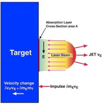
However, for usefully large forces - for example, enough to counteract gravity or accelerate a several-kg object to orbital speeds in a short time, laser ablation propulsion is more attractive than pure photon propulsion. Laser ablation propulsion operates, ideally in vacuum, by inducing a jet of vapor and plasma from a target using a laser pulse, which transfers momentum to the target (Fig. 1) [8]. Terminology is explained in more
detail in our review of the field [9].
2. Purpose of this paper
The purpose of this paper is to update the reference [2] analysis of propulsion into low Earth orbit (LEO) by including direct launch from the Earth, and to extend the analysis to interplanetary transfers at much higher velocity using new impulse coupling data we recently obtained. We first briefly review the physics and history of this field, then discuss the two applications. When mission duration is at a premium and laser power is not, we will show that Cm as low as 70 N/MW is a good optimum
for getting from LEO to Mars and 100–150 N/MW from ground to LEO. 3. Laser momentum transfer physics
The laser impulse coupling coefficient Cm is the ratio of momentum
delivered to a target by an ablation jet to the incident beam energy W for a laser pulse, or of surface pressure to incident intensity,
the Eq. (2) value for the Cm of light arises from the fact that the energy
density of light I/c is doubled on reflection. At 1 kW/m2 at our distance
from the Sun, a 10-km diameter reflective sail will generate 520 N thrust. Using this thrust, a 2 μm, 250-ton Al-coated plastic reflective film with this diameter could accelerate to 3 km/s in 17 days. The main problem is how to deploy such a film. Despite decades of development, the largest sail yet deployed (JAXA IKAROS [10], 2010) is 14 x 14 m.
Variable vE can be achieved by adjusting laser intensity on target – by
changing focal spot area, laser pulse duration and energy – which causes exhaust velocity to vary across the range from chemical reactions (approximately 5 km/s) to much higher values easily reaching 50 km/s. 10,000 K ion temperatures are readily created by a laser pulse. Exhaust velocity is only a matter of intensity [11]. Thrust can be varied inde- pendently of vE by changing the laser pulse repetition rate.
3.1. Ablation propulsion with pulsed lasers
Ablation efficiency is defined as in Eq. (3) where u is drift velocity:
2 2 2 2
ψ ¼ <vx>/<vx> ¼ (u þ2kT/me)/u (4)
Fig. 1. Impulse from laser ablation.
In Eq. (1), mT is target mass, p is surface pressure at the target, I is
intensity (W/m2), Φ ¼ Iτ is fluence on target (J/m2), vE is exhaust velocity
of the laser ablation jet and δμE is areal mass density (kg/m2) in the
ablation jet column created by one pulse. Cm has dimensions N-s/J or N/
W. Cm for pure-photon pressure is minute: the “momentum coupling
coefficient” for pure radiation reflecting off a polished surface is
Cm ¼ 2/c ¼ 6.7 mN/MW. (2)
A 10-kW laser reflecting perfectly off a surface would produce a thrust of only 67 μN. The other important parameter for any type of photon propulsion is propellant exit velocity, vE, simply c for light, but (2kTi/
mi)1/2≪c for laser ablation propulsion. Ti and mi are ion temperature and
mass.
Conservation of energy says that the efficiency of the whole process is
ηAB ¼ ψCmvE/2. (3)
The parameter ψ � 1, as we discuss after Eq. (4).
For very long trips, where time is available, solar sails represent a practical use of pure photon propulsion, taking advantage of the fact that, for light in reflection, Isp ¼ c/go, a very large number. The factor of 2 in
This parameter ψ is the result of the fact that the exhaust velocity distribution is a drifting maxwellian with a nonzero mean velocity. However, it can be shown [12] that high intensity ablation plumes correspond to ψ ::: 1.15, and we will assume ψ ¼ 1 for simplicity in
Fig. 3. Results from simulations of laser-powered flights to LEO [2] (with different assumptions than the present work).
Fig. 2. Illustrating optimum coupling Cmopt and fluence Φopt ¼ Ioptτ which occur when parameters are those to produce maximum Cm. Both vapor and plasma regime
Material→ Al POM
Pulsewidth Cm(N/MW) Φ(kJ/m2) Cm(N/MW) Φ (kJ/m2)
400fs 28 ± 3 50 ± 20 125 ± 12 32 ± 6
Fig. 4. Simulations in Ref. [2] showed that mass, mass ratio and cost optimize at different values of the coupling coefficient Cm.
Table 1
New laser momentum coupling results (1057 nm).
80ps 28 ± 3 3 0 ± 7 773 ± 70 40 ± 8
Fig. 5. Laser-propelled flyer.
discussing efficiency. If ψ is larger, Eq. (3) shows it's a bonus for ηAB.
The change in velocity of the target from a single pulse is
δvT ¼ CmΦ/μT (5)
Fig. 6. Geometry for laser launch.
Fig. 7. Laser station inserts the target into orbit. hf is final altitude. and
δvTjj ¼ ηcCmΦ/μT. (6)
In Eqs. (5) and (6), μT is the target's areal mass density, ηc is an
average geometrical efficiency factor taking account of the shape of the target and the fact that the ablation jet will be normal to each facet of its surface, not necessarily antiparallel to the laser beam. The quantity δvTjj
is the change in target velocity in the beam direction. Eq. (6) is a numerically convenient formulation for space applications because we can deliver a fluence Φ to a region containing the target and be sure that any object within that region having mass density μT and the same Cm
will gain the same velocity increment from the pulse. This is valid because space debris tend to exist in families with similar μT. For direct
comparison to electric propulsion engines, the thrust to electrical power ratio is
Cme ¼ ηeoCm. (7)
Laser electrical-to-optical efficiency ηεο can range from 25 to 80%,
depending on the laser type. Exhaust velocity can be determined from the product of the easily measured quantities Cm and Q (J/kg ablated) as
m T AB m AB mo m AB E m sp o Table 2
Ways to achieve initial target altitu de above denser part of atmosphere.
Method Problems Additional Est. Cost
in one pulse is
δx ¼ C2 Φ/(2ρ η ) (12)
and fuel use rate is
Balloon to • 35 km Uncontrolled $300/kg dm/dt ¼ 2 PηAB/(goIsp)2 (13) target position at laser turnon •To launch 6 targets, 9900 m3 volume
This can equivalently be written
dm/dt ¼ PC2 /(2η ) (14) Very large gun Loitering jet plane Black Brant Rocket 8 km tower •$45 k helium cost •Helium is a precious resource •1000 G's Acceleration •Need 1 km/s muzzle velocity •Facility cost dominant •Noise, gov't opposition •$3 k/hr cost •12 km max altitude •4 h/fuel load •8-target load at 50/day •One flight per target •$600 k/launch •Uncertain development cost •Uncertain stability •8 km not enough to help much $200/kg $60/kg to 12 km $2400/kg Uncertain
In Ref. [2], we took ηAB ¼ 1 for simplicity and because Q (or Isp) were
not measured for many materials. This is still true, because these are difficult to measure in single shots.
But we can play a trick: if we write
Cm¼CmoηAB (15)
and
P¼Po/ηAB, (16)
Eq. (14) becomes
dm/dt ¼ PoC2 /2 (17)
a constant as ηAB varies, as is thrust, F¼PoCmo. The rate of material
ablation is very small. As an example, for an aluminum target (density
ρT ¼ 2700 kg/m3), if Cm ¼ 70 N/MW, Φ ¼ 35 kJ/m2 and ηAB ¼ 1, Eq. (12)
gives δx ¼ 32 nm. At laser repetition frequency f ¼ 50 Hz, even in one minute operation, total ablation depth is 95 μm. We assume a perfectly uniform beam, such as is achievable with modern methods of apodization.
We note that a consequence of Eqs. (9) and (15) is that the rocket equation for the mass fraction delivered by a flight can be written
m/M ¼ exp (-CmoΔv/2), (18)
so that especially in space, with a small enough Cmo and adequate Po,
almost any mission is possible.
In the laser propulsion examples given in Figs. 8–12 and Table 3, initial laser average power is 5MW/ηAB. It increases as ηAB decreases, and
Cm decreases in the same ratio, so that thrust F¼PCm and fuel usage rate
are constant. Future measurements will tell us what ηAB is.
The laser-produced plasma jet is always perpendicular to the irradi-
Laser •Combusting target in atmosphere •Penalty on laser energy at lower launch altitude Zero additional cost
ated surface. Temperatures and pressures in plasma that can be achieved by an ultrashort-pulse laser interacting with a target in space range up to 100,000 K and 100 kbar with velocities of several km/s.
3.2. Optima
Q ¼ W/δmT ¼ Φ/δμT, (8)
it can be seen dimensionally that the product CmQ must be velocity:
vE ¼ CmQ. (9)
Note that δμT ¼ δμE by mass conservation. Eq. (9) can be extended to
show that ablation efficiency is given by
ηAB ¼ CmvE/2 ¼ δμEv2 /(2Φ) ¼ C I g /2, (10)
where go is the acceleration of gravity and Isp is the so-called specific
impulse. Cm and Isp are a constant product in which Isp varies inversely
with Cm for engines with the same efficiency. The units of Isp are seconds.
Another constant product is
C2 Q/2 ¼ η . (11)
There are a number of optima to consider in laser propulsion system design. One is the fluence which gives maximum Cm. Fig. 2 shows [13, 14] experimental and notional plots of Cm values vs. incident fluence Φ to
illustrate this optimum. In other work, we have called this Cm value and
the fluence at which it occurs Cmopt and Φopt.
There is another kind of optimum which gives minimum energy cost to complete a mission. From Fig. 3, it is clear that Cm ¼ 1000 N/MW had
an infinite cost for a 200s flight with the parameters of [2]. For these conditions, Fig. 3 shows that each mission had an optimum-cost impulse coupling coefficient. Lines are theory, dots are simulations for a real at- mosphere. Flight time depends on laser power. The purpose of Fig. 4 from Ref. [2] is to illustrate these optima. In Ref. [2], initial masses were 10 and 20.4 kg, and delivered payload mass was 6.1 kg. In the present work, we are not trying to minimize energy expenditure. Instead, we are trying to achieve absolute maximum payload mass fraction delivered at the end of the mission. In Ref. [2], initial mass is 25 kg and delivered mass as large as 13.5 kg. finite vE], mass delivered to LEO maximizes at CFig. 4 shows that mass ratio m/M maximizes at Cm ¼ 200 N/MW m ¼ 0
Because δμΤ ¼ ρTδx, the thickness of the solid target material ablated [in
Fθ ¼ PCmsinα, where (20)
F¼PCm¼(dm/dt)vE (21)
is the total force.
E
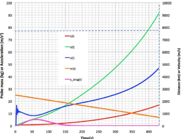
Fig. 8. Case 3. Single power launch from 1 km altitude with Cm ¼ 150 N/MW. Excessive vr produces -1.6 km perigee altitude. assumed ηAB ¼ 1 in Ref. [2], so exit velocity is vE ¼ 2/Cm. These optima
are specific to the ref. [2] case. In Ref. [2], delivered mass ratios were much lower than in the present work because we only considered P ¼ 1 MW, requiring larger Cm to counteract gravity and smaller zenith
angles. Different results are obtained in the present work which involves higher laser power levels. In consequence, more efficiency is reported in this work. Our work in laser propulsion is to find lasers and materials which achieve a desired optimum.
4. DIY coupling coefficient
In experiments conducted at the LULI Laboratory of E'cole Poly- technique [15], we measured Cm on several materials at 400fs and 80 ps,
1057 nm [Table 1]. In the future we will repeat the measurements at 528 nm, which may be more favorable for Cm. For our purposes, the most
important results were for Al and POM (polyoxymethylene, Delrin®). The latter material gave very large Cm at 10.6 μm with the Myrabo [16] flyer,
which achieved a flight altitude of 72 m in air in 2000 [17]. We found very high Cm for this material at 1057 nm, 80 ps. The same was not true at
400 fs. The POM Cm is too large for most laser launch projects [see Fig. 3],
but it is very useful in this way: we now plan to cast ablation fuel from a mixture of Al dust and POM to obtain any value we want in the range from 30 to 770 N/MW at 80 ps. As an example, an Al/POM mixture of 5% POM and 95% Al should give Cm ¼ 70 N/MW. Density of the combination
is 2640kg/m3, only slightly different from that of Al. The required flu- ence (~30kJ/m2) is about the same for both materials. For various reasons having to do with available laser hardware at 400 fs, this pulse duration is not attractive compared to 80 ps, so it doesn't concern us that Cmopt for POM at 400fs is much less than at 80 ps.
5. Laser launch from Earth to LEO
Fig. 5 shows our notional flyer design, both for launch to LEO and for
interplanetary travel (next section). Diameter is 50 cm. The craft is launched spinning about an axis perpendicular to the beam and very slowly presessing, so that all elements of the surface have equal exposure to the laser beam. A small canister and gas jets produce and maintain these rotations during launch. The mass of the insulation and discardable shell holding the ablator is assumed to be 0.5 kg. For the two cases, the ablator shell will have different Cm values and thicknesses. For LEO
launch through the atmosphere, as we will see, Cm will be in the range
110–150 N/MW, while for interplanetary travel Cm ¼ 70 N/MW. As we
will show, a craft designed to do both would have two layers: high Cm to
get to LEO and low Cm, for the interplanetary portion of the flight.
In Ref. [2], our method of laser-launching an object to low Earth orbit (LEO) was to separate the problem into two parts. First, we drove vertically through the atmosphere to altitude ho, leaving a vertical ve-
locity vro. Then, a second laser located at an appropriate distance to
satisfy the geometrical constraints applied as much tangential thrust as possible to achieve orbit. This was too complex. Figs. 7 and 8 show the launch geometry for the present work.
5.1. Equations of motion
Figs. 6 and 7 show the geometry for launch from Earth to LEO. Here, we include atmospheric drag in the simulations. Referring to Fig. 6 for the symbols, we note that
cosα¼(r2þz2—R2 )/(2rz) (19)
and that the tangential force on the spacecraft from incident laser power P is
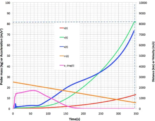
Fig. 9. Case 5. Our only successful single-power laser launch, from 35 km altitude to LEO with Cm ¼ 130 N/MW. Flight time 429s, laser range s(t). Altitude at insertion
is 409 km. Initial zenith angle is 60o and final zenith angle is 90o . Drag loss is significant, mass ratio delivered to orbit 28%. With final radial velocity 1.47 km/s and final velocity 9.09 km/s, vector velocity slope at insertion is barely acceptable (9.3o ) for a successful orbit. Perigee 112 km, apogee 10000 km.
Because
dL/dt ¼ m[r(dvθ/dt)þ(dr/dt)vθ] ¼ Fθnetr ¼ torque, (22)
dividing by r and including drag,
Fθ net ¼ (F—CdAρv2/2)sinα ¼ m{dvθ/dtþ[((dr/dt)/r)]vθ}, (23)
And Fr net ¼ (F—CdAρv2/2)cosα þ m[vθ 2/r—g Ro E E 2 /(R þ h)2] ¼ mdv /dt (24) r
In Eqs. (19) – (24), A ¼ (πDp2/4) is the exposed cross section area of the spherical flyer, Dp is the flyer diameter, ρ(h) is the atmospheric density – an exponential with scale height 7 km - at altitude h and v2 is the sum square of the radial and tangential velocities. In Eqs. (19)-(24), all quantities except the obvious constants are functions of time. ηc is a structural efficiency factor to account for the spacial average of the ablation thrust vector, which we take to be 0.8. Cd is the drag coefficient, vr is vertical velocity, μ is the target areal mass areal density (to match the dimensions of Φ), P is total laser power on target, and f is pulse repetition frequency.
5.2. Initial target altitude and ways to achieve it
The ways we considered are listed in Table 2. Ultimately, we decided the laser itself is the best method vs. balloons, guns, etc.
5.3. Launch strategy
A large number of factors interact to achieve a successful laser launch. Some of these are Cm, flight time, laser range, laser power, delivered mass fraction, final elevation angle, minimum altitude, insertion altitude and laser propagation range. Finding an optimum combination is a matter of art. We found that whatever you do with a laser on the earth's surface, even with the 5–15 MW average power rep-pulse laser which we
used here, it is easy to have the target disappear over the horizon before insertion as well as for it to have an undesirable amount of residual radial velocity. Best performance was obtained with Cm ¼ 120–150 N/MW. Compared to the cases discussed in Ref. [2], this choice increases fuel lifetime [see Eq. (17)].
5.4. Flights to LEO
Table 3 and Figs. 8–11 show our results. In our simulations, initial altitudes were chosen as 1, 10, 15 and 35 km. Laser beam range was always <2000 km. The laser station was assumed to be at 3 km altitude on a mountain so that large zenith angles are more manageable. Accel- eration was always modest.
5.4.1. Single phase flight
It is difficult to achieve good flight parameters when laser power is applied continuously. Fig. 8 (case 3 in Table 3) shows a bad example, in which launch from 1 km altitude produces excessive final radial velocity vrf, and perigee altitude is negative. Fig. 6 makes it clear why this hap-
pens. Even if the flight is initially tangent to the Earth's surface, after a long flight, angle α is no longer π/2 and an undesirable radial component of thrust exists. A solution is to launch higher.
We were not able to launch from the ground in any single-power flight. In case 3, beginning at 1 km altitude also involved significant loss to drag: delivered mass ratio was 23%. In the Fig. 9 flight (Case 5 of
Table 3), we launched from 35 km altitude to minimize energy expended in drag. Even so, only 28% of the mass survived into LEO despite the 35 km launch altitude. To avoid excessive vrf in a single-power flight, the
beam elevation angle must be small, leading to high drag in Case 5, and negative perigee in Case 3. The question of how best to get to 35 km still remains (Table 2). This was our only successful single-phase flight.
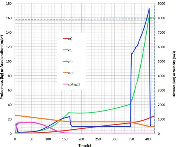
Fig. 10. Case 3A. Laser-launch from 1 km altitude lasting 160 s at 5 MW gets us above the atmosphere quickly. Then, a 180s coast followed by a 10 MW burst in the last 60s gets us into to LEO. Cm ¼ 150 N/MW. Initial zenith angle is 56o , final zenith angle 90o , mass ratio delivered to orbit 38%. Final radial velocity is 238 m/s and
final velocity 7.98 km/s. Perigee is 96 km and apogee is 842 km.
the point beneath the satellite at launch. T is flight duration. Tpkdrag is the
time at which drag is maximized. ϕo and ϕf are initial and final zenith
angles, ho, hp and ha initial, perigee and apogee altitudes, vrf final radial
velocity and sf final laser range to the spacecraft, amax is maximum ac-
celeration, m is mass delivered to orbit and M is mass on the ground. Perigee and apogee altitudes are assessed using Eqs. (25-28). In Eqs.
(25)-(26), μ is the gravitational parameter for Earth (rather than mass areal density), vf is total velocity, and vrf radial velocity at insertion,
g ¼ asin (vrf/v), and C ¼ rf vf cos(g), and we have 2 -1
apogee with 54% of launch mass delivered suggests applications to in- spection of GEO satellites.
5.5. Lasers
Laser parameters assumed in this work are listed in Table 4. Such high repetition rate, high pulse energy lasers are not yet demonstrated, but are being developed. The state of the art in the lasers we currently need to implement these applications is represented in the HiLASE program [18], where the Rutherford Appleton Laboratory's “DiPOLE 100” laser
ach-a ¼ (2/rf -vf /μ) (25) ieved 10 Hz, 100 J pulses at 10ns pulse duration. Higher repetition rate in
e ¼ [1-C2/(μa)]0.5 (26)
this monolithic laser design and higher capacity cooling are needed. Tens fiber lasers, but CW lasers are inappro-
ra ¼ (1 þ e)a (27)
rp ¼ (1-e)a (28)
5.4.2. Three-phase flight
Now, we use a different technique, in which an initial laser burst gets us above the atmosphere, we coast long enough to develop significant negative radial velocity and then apply a final burst at maximum azimuth angle at 2-3X normal power to achieve orbit with minimum radial ve- locity. This is called “heat capacity mode operation,” in which the laser medium is operated beyond its ability to dissipate heat continuously, for a short time.
Fig. 10 (case 3A) shows results of such a “three-phase flight.” Fig. 11
shows that a 45o initial zenith angle is permitted in a three-phase com-
plex flight profile [Table 3, Case 11B]. For this flight, the 41,700 km
of kW are available now in CW
priate for laser propulsion. Fiber amplifiers give much better heat dissi- pation, but 100 k pulsed fibers are necessary to generate 100 J pulses [15].
We prefer 1057 nm for the wavelength in atmosphere because ab- sorption is unacceptable at the second and third harmonics, especially at low elevation angles. In space, 355 nm is ideal. For energy storage, 6 GJ, 15 MW super batteries using zinc hybrid cathode technology have now been developed [19]. These batteries can be totally discharged without lifetime penalty. Because 10% discharge/recharge is the rule for most other battery types to ensure long life, this development increases battery mass efficiency by an order of magnitude.
5.6. Discussion
Why are the results here so much better than in Ref. [2]? The main reason is that much larger laser power allows us to oppose gravity with
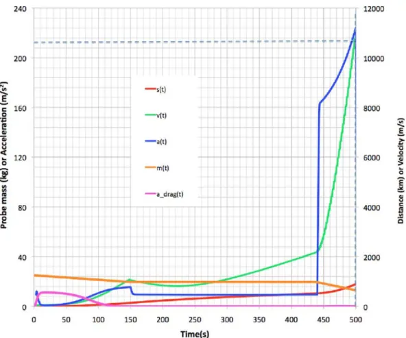
Fig. 11. Case 11B. Fascinating launch from ground (1 km altitude) with Cm ¼ 120 N/MW. A 300s coast followed by a 15 MW burst during 60 s at the very end gets our
craft into orbit. This profile gives m/M delivered to orbit of 54% (13.5 kg). Initial zenith angle 45.5o , final zenith angle 90o . Final radial velocity is 389 m/s, final
velocity 10.4 km/s, perigee 104 km, and apogee 41,700 km, 117% of geosynchronous altitude. Insertion slope is 2.12o . Minimal energy is wasted in drag, even though we are starting from the ground.
Table 3
Launch summary. Common parameter: P ¼ 5MW/ η AB. P doubles or triples at end.
Case Cm/ηAB (N/MW) Chord (km) T (s) T pk drag ϕo (o ) ϕf (o ) amax (m/s2) vrf (km/s) mf/M (%) ho (km) hp (km) ha (km) sf (km)
3 150 1.5 344 60 57 84 73 2.87 23 1 -1570 4080 1270
5 130 61 429 55 60 90 47 1.47 28 35 112 10,000 1680
3A 150 1.5 402 60 56 84 173 0.25 38 1 96 842 1030
11B 120 1 496 10 45.5 90 216 0.39 54 1 104 41,700 873
Table 4
Laser and target parameters.
Type Diode-pumped Nd
Wavelength 1057 nm for ground launch, 532 nm in space Pulse duration 100ps
Pulse energy 5 kJ
Pulse repetition rate 250 Hz/1kHz/2kHz/3 kHz Laser average power Po 1.25–15 MW
Target initial mass m 25 kg
Cmo Various, 70–150 N/MW
Db (Mirror diameter) 6 m/3 m
smaller Cm, and this leads to better insertion trajectory, higher Isp and
longer fuel life [Eq. (13)]. This is because higher temperature gives larger mass velocity in the laser-produced jet. Having 300% of normal power available in a burst at the end of the flight also vastly improves mass delivery, as we show in Table 3. This is our best case for a flight from the ground, with 54% of mass delivered to LEO (1 km starting altitude). Some calculations showed an m/M value of 61% from a 15 km starting
altitude.
To choose the best flight parameters, there are additional constraints: considering diffraction, scintillation and adaptive optics, maximum permissible range is 2000 km for 1060 nm and a 6-m mirror.
This launch technique can easily reach very large apogees. Delivered mass fraction was very impressive. Contrary to our expectations, launching directly through the atmosphere was possible.
5.7. Energy cost perspective
For the simulations reported in Fig. 5, the minimum emitted laser beam energy cost per kg delivered to orbit was 80 MJ/kg. In case 11B, this cost was 120 MJ/kg. In Ref. [2], we assumed perfect alignment of the beam with the target trajectory, which was supposed to have been ach- ieved with a guidance system and tilting reflectors on the tail of the flyer. In this work, we use a more realistic target that always provides reaction along the beam axis without special mirrors or guidance, but the thrust vector is not perfectly aligned with the path to orbit. This explains the difference in energy cost. The inherent total energy change to create the orbits in Table 3 vary from about 2.4 MJ/kg to 24 MJ/kg. Riding an
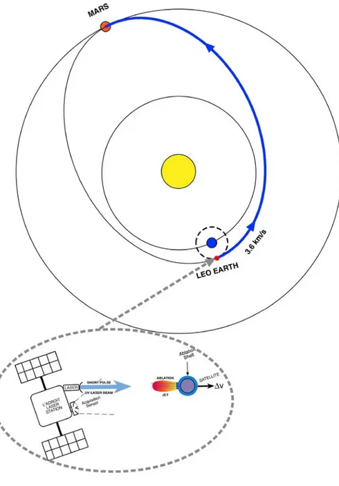
Fig. 12. A cis-Mars trajectory starting from LEO re- quires Δv ¼ 3.6 km/s.
elevator to 150 km amounts to 1.5 MJ/kg. A bullet with 7.98 km/s ve- locity contains 32 MJ/kg. The parameter Q in Eq. (8) is related to, but incommensurate with, all these values, because it relates to the mass ablated rather than the mass delivered. Q derived from Eq. (11) for a typical flight at 120 N/MW is 140 MJ/kg.
6. Laser-powered rockets
In this section, we consider a laser-propelled rocket, consisting of the
Fig. 5 flyer. Flight trajectory is shown in Fig. 12. This is an instantaneous launch, from the point of view of the astrodynamics. Here, we don't have to worry about minimum perigee.
6.1. Equations of motion
The equation of motion in this case is very simple:
d2s/dt2 ¼ PoCmoηc/m (29)
because there is no drag. The laser and the target are in a micro-G
environment in LEO, not on the ground. Because an object launched from LEO as shown in Fig. 13 needs a Δv of 3.6 km/s to reach its goal, our only problem is to generate this Δv, rather than worrying about the detailed gravity fields of Earth and the Sun between LEO and Mars. Earth and Sun gravity influence the flight along the way, but all we need to know at the outset is the required Δv and pointing direction, and to deliver it quickly. A flight result is shown in Fig. 13. Mass fraction delivered to Mars is 73%.
6.2. Discussion
The laser-powered rocket is an exciting project for future research. This laser is powered from high performance 6 GJ “super-batteries” [19] which are recharged by solar panels in one day at a 70 kW rate. Laser power is only 1.25 MW, not 5, and can be the third Nd harmonic (355 nm) in space. For this reason the mirror can have 3 m diameter rather than 6 m, as in the LEO launch analysis. Although Cm and Isp have
not been measured at 355 nm, theory [ref. (3)] says Cm should be better
at the shorter wavelength. We remind the reader that the laser power and Cm values listed in Table 5 should be understood to be adjusted according
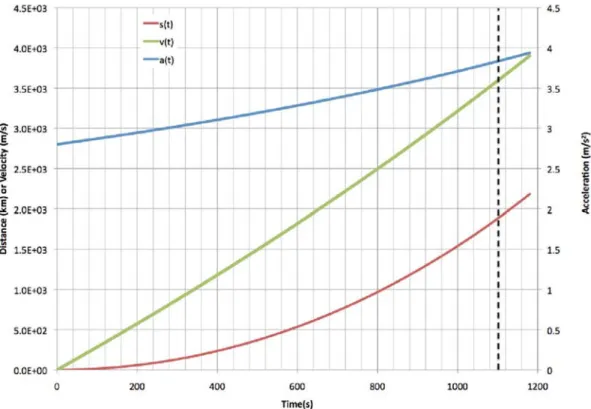
Fig. 13. The necessary velocity of 3.6 km/s is obtained after accelerating for 18.5 min, and 18.2 kg is delivered to the cis-Mars trajectory.
Table 5
Parameters for flight to Mars.
Wavelength (nm) 355 Pulse duration (ps) 100 Pulse energy (kJ) 5 Repetition rate (Hz) 250 Average power (MW) 1.25 Cm(N/MW) 70 Fluence Φ (kJ/m2) 35 Target diameter (cm) 50 Initial mass (kg) 25 Final mass (kg) 18.2 (73%) Final velocity (km/s) 3.6 Acceleration time (min) 18.5 Mirror diameter (m) 3 Maximum range (km) 1900 Maximum acceleration (m/s2) 3.84 Ablation efficiency 1.0
to Eqs. (15)–(16) when ablation efficiencies are known. If such a flight were concatenated with a maximally efficient launch from ground to LEO, total mass fraction would be 39% from Earth to Mars, using a combination of groundbased and spacebased lasers. But, that's another paper!
7. Conclusions
For several years, scientists have been launching thin foils with short- pulse lasers to 8 km/s velocities [20]. A way to understand the work reported here is that we launch the equivalent of 400,000 or so thin foils at similar velocities toward the laser beam, one at a time, and the reaction momentum propels a craft in space efficiently.
For the first time, we showed it is possible to laser launch directly from the Earth's surface, and still obtain excellent mass fraction m/M greater than 50% delivered to LEO. This is more than a factor-of-10 improvement over state of the art m/M ratios with chemical rockets. This, an exciting result of this study, can be utilized by assembling larger
stations on orbit from pieces, or for launching swarms of micro- or nanosatellites at low cost.
We used a novel design in which a sphere covered with ablation fuel is caused to rotate randomly so that the entire surface is used for fuel, creating a jet which is always directed opposite to the laser beam. Rotation is presumed to be caused by, e.g., gas jets from a small internal canister. The direction of the beam itself governs the direction of the sphere's trajectory.
These are all passive ablation fuels. As we showed in Ref. [11], it is possible to obtain 3-4 times larger Cm with energetic materials like gly-
cidyl azide polymer (GAP).
In the absence of accurate data on specific impulse Isp for our target
materials, we showed that it is still possible to use a scaling with laser power inversely proportional to ηAB and coupling coefficient Cm pro-
portional to ηAB to provide constant thrust and fuel lifetime.
Flight times to LEO were 250–540s. Initial laser power was 5MW/ηAB
and the probe initial mass was 25 kg. In the best cases, a burst of 10–15 MW/ηAB was applied in the last 80s, producing a significant increase in
m/M as well as a better values for final orbit parameters.
If a practical, low-cost way (balloon, gun, tall tower) is developed to lift the flyers to 15 km before laser acceleration, we showed even better m/M values for the overall flight. The cost of doing this may not be worthwhile. The gains for initiating the flight at 35 km rather than 15 km are probably not worth the additional effort.
Our calculations show that this technology, combined with a 1B$ groundbased laser station capable of 30 launches/day, can reduce launch costs to LEO to about $300/kg, a factor of 30 below present experience, because station cost is dominant at high launch rate.
An important application of this work is to launching constellations of Earth-observing microsatellites, to more carefully monitor global climate change and its consequences, in order to spot trends at the earliest possible time and to develop very highly detailed global models. Another application is to sending inspection craft to geosynchronous (GEO) orbit.
The second important result of this work is that it is not difficult to send a probe to Mars in a year or so, with 73% of the mass surviving. Laser wavelength should be the Nd 3rd harmonic in this case (355 nm) because of its better Cm and lower divergence, making possible smaller
mirrors than for the LEO launch case. Maximum laser range was 2000 km.
Further applications of this work are to longer flights within the solar system on one extreme of difficulty, and to placing satellites in LEO or GEO orbits on the other. As higher power lasers are developed, larger masses than 25 kg can also be laser-launched.
Because of Eq. (18), almost any goal can be reached starting from LEO with a sufficiently small Cmo, and sufficient laser power.
Acknowledgments
This paper is the written version of Paper no. 679, presented at the
7th European Conference for Astronautics and Space Sciences (EUCASS), Politecnico di Milano, 3–6 July 2017.
The research of my coauthors developing the Table 1 data and exploring a new area in Space Science was partly funded by the CNES through grant AVP-CT-0-1603. The authors thank the LULI Program Committee for having allocated pluriannual beamtime for us to use the ELFIE facility 16TW-F6.
C. R. Phipps benefited immensely from discussions with coauthors, especially Messrs. Bonnal and Masson during development of this topic. C. R. Phipps' work did not receive any specific grant from funding agencies in the public, commercial, or not-for-profit sectors.
Appendix A. Supplementary data
Supplementary data related to this article can be found at https://doi.org/10.1016/j.actaastro.2018.02.018.
Acronyms and abbreviations
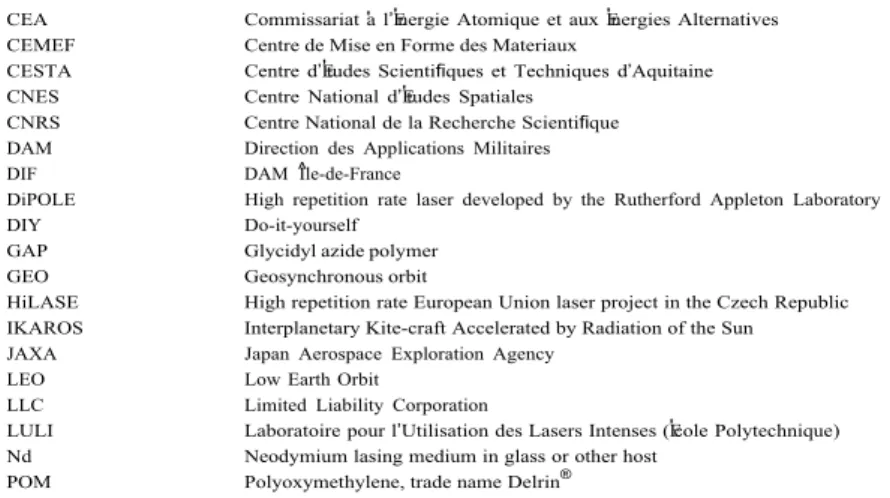
Table 6: Acronyms and abbreviations used in this work.
CEA Commissariat 'a l’E'nergie Atomique et aux E'nergies Alternatives CEMEF Centre de Mise en Forme des Materiaux
CESTA Centre d’E'tudes Scientifiques et Techniques d’Aquitaine CNES Centre National d’E'tudes Spatiales
CNRS Centre National de la Recherche Scientifique DAM Direction des Applications Militaires DIF DAM ^Ile-de-France
DiPOLE High repetition rate laser developed by the Rutherford Appleton Laboratory DIY Do-it-yourself
GAP Glycidyl azide polymer GEO Geosynchronous orbit
HiLASE High repetition rate European Union laser project in the Czech Republic IKAROS Interplanetary Kite-craft Accelerated by Radiation of the Sun JAXA Japan Aerospace Exploration Agency
LEO Low Earth Orbit
LLC Limited Liability Corporation
LULI Laboratoire pour l’Utilisation des Lasers Intenses (E'cole Polytechnique) Nd Neodymium lasing medium in glass or other host
POM Polyoxymethylene, trade name Delrin®
References
[1] C.R. Phipps, M. Michaelis, LISP, J. Laser Part. Beams 12 (1) (1994) 23–54. [2] C.R. Phipps, J. Reilly, J. Campbell, Optimum parameters for laser-launching objects
into low earth orbit, J. Laser Part. Beams 18 (4) (2000) 661–695.
[3] C.R. Phipps, C. Bonnal, A spaceborne, pulsed UV laser system for re-entering or nudging LEO debris, and re-orbiting GEO debris, Acta Astronaut. 118 (2016) 224– 236.
[4] F. Tsander, Flight to other planets, in: Ye Moshkin (Ed.), Development of Russian Rocket Technology, Mashinostroyeniye Press, Moscow, 1924 (1973) (in Russian). [5] K. Tsiolkovsky, Plan of Space Exploration, 1926 (in Russian), available in English in “Exploration of the Universe with Reaction Machines: Exploring the Unknown,” NASA History Series. NASA SP 4407, Washington, D.C. (1995).
[6] H. Oberth, Die Rakete zu den Planetenr€aumen (The Rocket to the Planet Spaces), Oldenbourg Verlag, München, 1923.
[7] E. S€anger, Zur Theorie der Photonenraketen, Probleme der Weltraumforschung (IV), in: Internationaler Astronautischer Kongress, Zürich 1953; S. 32, Laubscher, Biel-Bienne, 1955.
[8] C.R. Phipps, Pulsed lasers for clearing debris in LEO and GEO, paper LSSE1-1, in: Optics and Photonics International Conference, Yokohama, 17–20 May 2016, 2016. [9] C.R. Phipps, M. Birkan, W. Bohn, H.-A. Eckel, H. Horisawa, T. Lippert, M. Michaelis,
Y. Rezunkov, A. Sasoh, W. Schall, S. Scharring, J. Sinko, Review: laser ablation propulsion, J. Propul. Power 26 (4) (2010) 609–637.
[10] H. Yano, Cosmic dust detection by the IKAROS large area dust detectors ion interplanetary space from the Earth to Venus, in: 42nd Lunar and Planetary Science Conference, 2011 [in Japanese].
[11] C.R. Phipps, J. R.Luke, W. Helgeson, Laser-powered, multi-Newton thrust space engine with variable specific impulse, in: High-Power Laser Ablation VII, Proceedings of SPIE 7005, 1X1-1X-8, 2008.
[12] C.R. Phipps, J.R. Luke, Laser space propulsion, in: Laser Ablation and its Applications, Chap.16, Springer, 2007, pp. 407–434.
[13] C.R. Phipps, J.R. Luke, D. Funk, D. Moore, J. Glownia, T. Lippert, Laser impulse coupling at 130fs, Appl. Surf. Sci. 252 (2006) 4838–4844.
[14] Courtesy of H.-A. Eckel, DLR Stuttgart, 2016.
[15] C.R. Phipps, M. Boustie, J.-M. Chevalier, S. Baton, E. Bambrink, L. Berthe, M. Schneider, L. Videau, S.A.E. Boyer, S. Scharring, Laser impulse coupling and ablated mass measurements at 400fs and 80ps using the LULI facility at 1057nm wavelength, J. Appl. Phys. 122 (2017) 193103, https://doi.org/10.1063/ 1.4997196.
[16] L.N. Myrabo, D.G. Messitt, F.B. Mead Jr., Ground and flight tests of a laser propelled vehicle, paper AIAA 98-1001, in: 36th AIAA Aerospace Science Meeting & Exhibit, 1998, 12-15 January 1998, Reno, NV.
[17] L.N. Myrabo, World record flights of beam-riding rocket lightcraft: demonstration of ‘disruptive’ propulsion technology, paper AIAA 2001-3798, in: 37th AIAA/ ASME/SAE/ASEE Joint Propulsion Conference, 2001, 8-11 July 2001, Salt Lake City, UT.
[18] HiLASE Project, Czechia, Advanced DPSSL Laser, DiPOLE 100, Delivers 1kW Performance, 2016. http://www.hilase.cz/en/advanced-dpssl-laser-dipole-100- delivers-1kw-performance/.
[19] See https://eosenergystorage.com/products-technology/ for high energy density ZNYTH Zinc Hybrid Cathode Technology.
[20] Z. Gong, et al., Experimental Study for Laser-driven Flyer Plates up to 8km/s, International Astronautical Federation, 2015 paper IAC-15, A6,3,8,x29049.
C. R. Phipps earned a Ph.D. from Stanford University in 1972 and B.S. and M.S. degrees from the Massachusetts Institute of Technology. He worked at Lawrence Livermore Labo- ratory and Los Alamos National Laboratory before forming Photonic Associates, LLC in 1995. His interest in laser propulsion goes back to that year.
![Fig. 4. Simulations in Ref. [2] showed that mass, mass ratio and cost optimize at different values of the coupling coefficient C m](https://thumb-eu.123doks.com/thumbv2/123doknet/7435362.220164/4.892.481.819.83.443/simulations-showed-ratio-optimize-different-values-coupling-coefficient.webp)