Pépite | Intégration du retour tactile sur des objets mobiles communicants : analyses et spécifications
147
0
0
Texte intégral
(2) Thèse de Thomas Sednaoui, Lille 1, 2016. © 2016 Tous droits réservés.. lilliad.univ-lille.fr.
(3) Thèse de Thomas Sednaoui, Lille 1, 2016. LILLE UNIVERSITY. Résumé L2EP- Laboratoire d’électrotechnique et d’électronique de puissance de Lille. Docteur en Sciences Pour L’Ingénieur. Intégration du retour tactile sur des objets mobiles communicants : analyses et spécifications Par Thomas Sednaoui. L’usage des écrans tactiles est devenu omniprésent ces dernières années. Ces appareils prennent une place de plus en plus importante dans notre de vie de tous les jours, on les retrouve dans nos maisons, bureaux et même dans nos poches. L’abondance de ces nouvelles interfaces a soulevé l’intérêt pour les technologies permettant une stimulation tactile, et mis en perspective le manque de ce type d’interfaces dans les nouvelles générations d’appareils mobiles avec écrans tactiles. Aujourd’hui, les appareils possédant ce type d’écran se contentent de fournir un retour sensoriel sous la forme de simples vibrations, qui n’ont pas pour objectif de recréer les sensations du toucher de surfaces. La recherche de nouvelles interfaces tactiles, plus performantes, et assurant une restitution plus proche d’une sensation naturelle est donc en cours. Plusieurs solutions technologiques ont prouvé leur efficacité mais posent des problèmes d’industrialisation. Dans cette thèse, une de ces méthodes adaptées aux écrans tactiles, la lubrification ultrasonique, est présentée. Cette méthode de stimulation s’appuie sur la création d’une onde stationnaire ultrasonore au sein d’un résonateur en verre et est capable de faire varier en temps réel la sensation de frottement entre le doigt de l’utilisateur et la surface du résonateur. Grace à des mesures tribologiques, les paramètres influents tels l’amplitude vibratoire, la vitesse d’exploration du doigt, la fréquence de résonance du stimulateur sont mis en évidence. Cette analyse permet la proposition d’une première série de spécifications techniques pour la conception de dispositifs à retour tactile. L’étude est ensuite complétée par l’analyse des problèmes d’alimentation et de contrôle du système, avec en considération les questions d’intégration au sein de dispositifs portables et les problèmes d’industrialisation du processus de fabrication. Enfin, des études psychophysiques sont menées pour affiner du point de vue perceptuel le cahier des charges de conception d’un tel dispositif.. © 2016 Tous droits réservés.. lilliad.univ-lille.fr.
(4) Thèse de Thomas Sednaoui, Lille 1, 2016. © 2016 Tous droits réservés.. lilliad.univ-lille.fr.
(5) Thèse de Thomas Sednaoui, Lille 1, 2016 ii. Contents. LILLE UNIVERSITY. Abstract L2EP- Laboratoire d’électrotechnique et d’électronique de puissance de Lille. Doctor in Engineering Sciences. Tactile feedback integration on mobile communicating devices: analysis and specification By Thomas Sednaoui. The last few years have seen the emergence of ubiquitous mobile devices and tactile interfaces. These devices take an ever-important place in our daily life, they are present in our home, office, cars and even pockets. The abundance of these novel interfaces raised the interest in touch based human-machine interactions and highlighted the problem of the lack of natural touch feedback in the existing generation of tactile displays. Today’s smartphones all possess basic haptic feedback thanks to low frequency vibrations. However, these vibrations are far from the natural touch sensation of a surface. The search for a better tactile feedback, closer to the natural human perception, is ongoing. Multiple solutions are being explored to deliver improved haptic feedback on existing mobile platforms such as smartphones or tablets. In this thesis, we investigate the tactile feedback thanks to ultrasonic lubrication, well adapted to touch screen. This technology uses the creation of a resonating standing wave in a substrate to modulate in real time the friction perceived by user moving his finger on the resonator surface; the principle is effective even on a flat glass surface. By a series of experimental friction measures, the influence of the relevant parameters such as the vibration amplitude, the exploratory speed, the resonance frequency is highlighted. This analysis is used to build advanced tactile interfaces, based on ultrasonic friction modulation. The control and the supply of the tactile interfaces are also investigated, considering the issues of integration and industrialization of the process. Finally, these new interfaces are used to explore advanced control methods, improving further the quality and reliability of the generated sensation. Psychophysical analysis is performed to fulfil the specifications of these devices on a perceptual point of view.. © 2016 Tous droits réservés.. lilliad.univ-lille.fr.
(6) Thèse de Thomas Sednaoui, Lille 1, 2016 iii. Contents. CONTENTS Contents ..................................................................................................................................... 3 Acronyms .................................................................................................................................... 6 Introduction................................................................................................................................ 7 1. Literature Review ................................................................................................................ 0 1.1. Introduction ................................................................................................................. 1. 1.2. Haptic: Fooling The Human Perception of Touch........................................................ 2. 1.2.1. General anatomy of the human hand related nervous system ........................... 2. 1.2.2. Cells and Corpuscles involved in tactile sense ..................................................... 3. 1.2.3. Discrimination of frequencies .............................................................................. 7. 1.2.4. Creating Haptic Illusions ....................................................................................... 7. 1.3. Tactile Stimulation Adapted to Mobile Devices ........................................................ 10. 1.3.1. Growth of the haptic industry ............................................................................ 10. 1.3.2. Vibrating Load .................................................................................................... 11. 1.3.3. Texture based tactile feedback .......................................................................... 12. 1.4. Tactile Stimulation Mediated by Ultrasonic Lubrication Effect ................................ 16. 1.4.1. Development of the UL based tactile stimulation ............................................. 16. 1.4.2. Design and Optimization of an Ultrasonic Lubrication plate ............................. 19. 1.5. Conclusion ................................................................................................................. 24. 2 Physical characterization of the interface between human fingers and an ultrasonic vibrating surface ....................................................................................................................... 25 2.1. Objectives: Creating a set of design guidelines for the designers of UL displays ..... 26. 2.2. Description of the methodologies ............................................................................. 28. 2.2.1. Design and control of the UL devices specialized for tribological measures ..... 28. 2.2.2. Tribometric approach to measure the dynamic friction coefficient.................. 29. 2.3. © 2016 Tous droits réservés.. Asymptotic limit of achievable reduction of the friction coefficient ........................ 34. 2.3.1. Objectives of the Experiment ............................................................................. 34. 2.3.2. Experimental Setup ............................................................................................ 34. 2.3.3. Evaluation of the Friction Reduction Results ..................................................... 38. 2.3.4. Conclusion .......................................................................................................... 42. lilliad.univ-lille.fr.
(7) Thèse de Thomas Sednaoui, Lille 1, 2016 iv. Contents. 2.4. Influence of the Resonant Frequency on Ultrasonic Friction Reduction Devices ..... 43. 2.4.1. Objectives of the Experiment ............................................................................. 43. 2.4.2. Experimental Setup ............................................................................................ 44. 2.4.3. Evaluation of the Friction Reduction Measures ................................................. 46. 2.4.4. Conclusion .......................................................................................................... 49. 2.5. Comparison of measured data with existing models ................................................ 51. 2.5.1. Historical background on the Ultrasonic Lubrication ........................................ 51. 2.5.2. Evaluation of the Squeeze Film model ............................................................... 51. 2.5.3. Evaluation of the Intermittent Contact Spring Model ....................................... 55. 2.5.4. Conclusions......................................................................................................... 63. 2.6. List of Requirements for an ULD and Design Rules ................................................... 64. 2.6.1. Amplitude of Vibration ....................................................................................... 64. 2.6.2. Frequency of the resonant mode....................................................................... 64. 2.6.3. Rise time of the Vibration Amplitude ................................................................ 64. 2.6.4. Conclusion .......................................................................................................... 65. 3 Design and Development of Optimized Tactile Devices Integrating Haptic and Visual Feedbacks ................................................................................................................................. 67 3.1. Introduction ............................................................................................................... 68. 3.2. Coupling Visual and Tactile Feedbacks ...................................................................... 69. 3.2.1. Engineering challenges of coupling UL and visual feedbacks ............................ 69. 3.2.2. Optimized Transparent UL Stimulator: Discreet Piezoelectric Actuators .......... 70. 3.2.3. Optimized Transparent UL Stimulator: Thin Film Piezoelectric Actuators ........ 78. 3.3. 3.3.1. Description of the goal of a piezoelectric driver and its constraints: ................ 87. 3.3.2. Power inverter and amplifier dedicated to UL stimulation ............................... 87. 3.3.3. Topology of piezoelectric driver ......................................................................... 89. 3.3.4. Description of the design of simple H bridge piezoelectric amplifier: ............... 90. 3.3.5. Low level signal generation and control system ................................................ 91. 3.3.6. Final realization and integration of the optimized piezoelectric driver ............ 95. 3.4 4. © 2016 Tous droits réservés.. Design of a Control System Adapted to Optimized UL Feedbacks ............................ 87. Conclusion ................................................................................................................. 97. Psychophysical studies of Multi-Sensorial Interfaces ....................................................... 98. lilliad.univ-lille.fr.
(8) Thèse de Thomas Sednaoui, Lille 1, 2016 v. Contents. 4.1. Introduction ............................................................................................................... 99. 4.2. Methodologies ......................................................................................................... 100. 4.2.1 4.3. Introduction to the psychophysical protocols and analysis ............................. 100. Perceptive thresholds assessment of the UL single pulse modulation parameters 103. 4.3.1. Introduction and psychophysical protocol....................................................... 103. 4.3.2. Minimal perceptible signal duration ................................................................ 103. 4.3.3. Minimal perceptible response time ................................................................. 105. 4.4. Optimization of the power consumption through duty cycle reduction ................ 107. 4.4.1. Introduction...................................................................................................... 107. 4.4.2. Psychophysical protocols ................................................................................. 108. 4.4.3. Results of the duty cycle modulation ............................................................... 109. 4.4.4. Impacts on the energy consumption ............................................................... 111. 4.4.5. Comparison with existing solutions and conclusion ........................................ 113. 4.5. Cross compensation of UL modulation parameters ................................................ 115. 4.5.1. Introduction...................................................................................................... 115. 4.5.2. Psychophysical protocol ................................................................................... 115. 4.5.3. Evaluation of the preliminary results ............................................................... 116. 4.6. Perspectives and Conclusion ................................................................................... 118. 4.6.1. Discussion on the fidelity of the psychophysical curves fitting ....................... 118. 4.6.2. Conclusions....................................................................................................... 119. Conclusions And Perspectives ................................................................................................ 120 Annex A: Bandwidth Estimation............................................................................................. 122 Annex B: Thin Film Deposition for a Transparent 4 inch Display ........................................... 123 Annex C: Alternative Psychophysical Fits ............................................................................... 125 References .............................................................................................................................. 126. © 2016 Tous droits réservés.. lilliad.univ-lille.fr.
(9) Acronyms. Thèse de Thomas Sednaoui, Lille 1, 2016 vi. ACRONYMS AC AlN Au CAD CPU DC DSP EMI ERM FA I FA II FE FEM GUI HMI JND LCD LRA MCU Mo PCB PWM PZT RLC RT SA I SA II SAW SiO2 SL SNR THD UL. © 2016 Tous droits réservés.. Alternative Current Aluminum nitrate gold Computer Assisted Design Central Processing Unit Direct Current Digital Signal Processor Electromagnetic Impulsions Eccentric Rotating Mass fast Adapting 1: Meissner cells Fast Adapting 2 : Pacini corpuscles Finite Element Finite Element Method Graphical User Interface, graphical user interface Human Machine Interfaces Just Noticeable Difference Liquid Crystal display Linear Resonant Actuator Microcontroller Unit Molybdenum Printed Board Circuit Pulse-Width Modulation Lead zirconium titanate Resistance Inductance Capacitor Rise Time Slow Adapting 1: Merkel cells Slow Adapting 2 : Ruffini corpuscles Surface Acoustic Wave silicon oxide Signal Length Signal to Noise Ratio Total Harmonic Distortion Ultrasonic Lubrication. lilliad.univ-lille.fr.
(10) Thèse de Thomas Sednaoui, Lille 1, 2016 vii. Introduction. INTRODUCTION Context Human is a visual and social based creature, and it is thus natural that when the technology became available, the first Human Machine Interfaces (HMI) were focused on the replication of vision and sound. First mobile phones continued this tendency with the implementation of a simple screen and mechanical keyboard, fulfilling all the users’ needs. But with the advance of silicon and miniaturization, mobile phones changed name to be called smartphones, reflecting their increasing processing power and applications. Simple mechanical HMIs proved unadapted to the efficient control of such complex devices. In 2007, a full touch screen device was the game changer. It solved a problem that is, by its nature, grounded in the necessary modularity of complex visual interface. Previous smartphones were limited in their functions, not by technical capabilities and processing power, but by the need for a modular interface that could adapt to the growing need of the users: phone call of course, but also internet browser, text editor, media player, and photo and video camera. But full touch screen was soon revealed to carry a new inconvenience, felt by users as a step backward in ergonomics. Interacting with a purely visual interface without any inherent tactile sensations felt wrong. And while nowadays most smartphone owners are used to this problem, the search for a solution was not abandoned by industrials and researchers. Today, multiple technological advancements give hopes that such an HMI will soon be found. With the objective of giving the illusion of a natural touch sensation on touch screen devices, this work focuses on friction modulation: the ability to dynamically change the tribologic conditions between a surface and a user’s finger sliding on it. This effect can be reached through several technologies, but the results are similar, they offer the possibility to recreate different roughness or even textures on a perfectly flat glass surface.. PROTOTOUCH Project This work is part of the European Marie Curie project PROTOTOUCH (www.prototouch.com). This project focuses on the next generation of haptic and tactile interfaces, for the implementation of high definition haptic feedback, i.e. the simulation of the tactile sensation of a texture or a pressed button. The main research goal is to exploit multiscale multiphysics simulation software, supported by neurophysiological measurements, for the virtual prototyping and optimization of tactile displays. With the associated research activities, the project will lead to a radical understanding of the underlying design principles and hence to the development of future generation devices. This objective was achieved by the deployment of an inter-disciplinary network involving experts in tactile displays, computer simulation,. © 2016 Tous droits réservés.. lilliad.univ-lille.fr.
(11) Thèse de Thomas Sednaoui, Lille 1, 2016 viii. Introduction. cognitive and neural sciences, psychophysics, information processing, material science, tribology and medical rehabilitation. The inter-sectoral dimension of the consortium links fundamental and applied scientists and engineers in 7 universities. This thesis is the result of a partnership between two members of the PROTOTOUCH Consortium: the company STMicroelectronics (Crolles, France), and the laboratory L2EP in the University of Lille1 (Lille, France). The main objective of my thesis within the consortium and through this partnership, was to develop a better understanding of tactile stimulation mediated by Ultrasonic Lubrication (UL) thanks to experimental measurements and to implement optimized design for the integration of this technology within touch based mobile phones.. Thesis Structure This manuscript is organized into four parts: Chapter 1: This chapter is an introduction to the biological mechanoreceptors involved in the human tactile sense. The anatomical distribution and the electromechanical characteristics of the multiple mechanoreceptors used to perceive touch are described in a first part. In a second part, a review of the different technologies adapted to the fingertip stimulation for mobile device is done. Finally, a more complete look is given to friction modulation mediated by Ultrasonic Lubrication (UL) effect, which is the focus of this thesis. Chapter 2: In order to gain a better understanding of the UL effect and how it could be better harnessed for the improvement of friction modulation, a series of tribology experiments were conducted. This work, which combines in vivo experiment and measurements with an artificial finger, was used as the groundwork for the refining of the theory behind the Ultrasonic Lubrication effect. Following this better understanding, a set of new design rules for the realization of future UL devices will be presented. Chapter 3: This chapter capitalizes on the explorative study of the UL effect performed in Chapter 2 and deduces the development process of a series of optimized tactile HMIs. The main problematics which occur while designing a new UL based tactile device are reminded, including integration and industrialization issues. In a second part, the development process of a piezoelectric driver and its control, dedicated to UL devices, is presented and characterized. Chapter 4: With the help of an advanced UL tactile HMI presented in Chapter 3, a series of psychophysical experiments are conducted to evaluate the limits of the human perception of UL effect. Control systems are then presented to take advantage of these limits to improve the repeatability of the stimulation and to reduce the power consumption of UL devices.. © 2016 Tous droits réservés.. lilliad.univ-lille.fr.
(12) Thèse de Thomas Sednaoui, Lille 1, 2016. © 2016 Tous droits réservés.. lilliad.univ-lille.fr.
(13) Thèse de Thomas Sednaoui, Lille 1, 2016. 1 LITERATURE REVIEW Summary 1. Literature Review. 0. 1.1. Introduction. 1. 1.2. Haptic: Fooling The Human Perception of Touch. 2. 1.2.1. General anatomy of the human hand related nervous system. 2. 1.2.2. Cells and Corpuscles involved in tactile sense. 3. 1.2.3. Discrimination of frequencies. 7. 1.2.4. Creating Haptic Illusions. 7. 1.3. 10. 1.3.1. Growth of the haptic industry. 10. 1.3.2. Vibrating Load. 11. 1.3.3. Texture based tactile feedback. 12. 1.4. Tactile Stimulation Mediated by Ultrasonic Lubrication Effect. 16. 1.4.1. Development of the UL based tactile stimulation. 16. 1.4.2. Design and Optimization of an Ultrasonic Lubrication plate. 19. 1.5. © 2016 Tous droits réservés.. Tactile Stimulation Adapted to Mobile Devices. Conclusion. 24. lilliad.univ-lille.fr.
(14) Chapter 1.1: Introduction. Thèse de Thomas Sednaoui, Lille 1, 2016 1. 1.1 INTRODUCTION The last few years have seen the emergence of ubiquitous mobile devices and tactile interfaces. These devices take an ever-important place in our daily life, they are present in our home, office, cars and even pockets. The devices shown in Figure 1-1 are all common appliance of the consumer market in todays developed world. The abundance of these novel interfaces raised the interest in touch based human-machine interactions and highlighted the problem of the lack of natural touch feedback in the existing generation of tactile displays. This problem was partly responsible for the first slow adoption of the touchscreen technology among consumers. First attempts made in 1985 to add tactile feedback to these first generations of touchscreen showed the ergonomic difficulty of the process [1]. Today’s smartphones all possess basic haptic feedback thanks to low frequency vibrations. The search for a better tactile feedback, closer to the natural human perception, is ongoing. Multiple solutions are being explored to deliver improved haptic feedback on existing mobile platforms such as smartphones or tablets.. Figure 1-1: Common Interfaces based on touchscreen technology. The first part of this chapter is dedicated to a better understanding of the biological and anatomical concept of touch for humans. The perception of touch is a complex fusion of the signals sent by multiple specialized cells. The categorization of these structures is necessary to the understanding and classification of the different modalities of tactile exploration. Based on this understanding of the human touch, a survey of the methods developed to simulate its effects will be presented. The final goal of these methods is to replicate the natural feel of touch on touch screen devices; or at least to create a tactile stimulation which makes sense for finger based perception Finally, a deeper look will be given to one of these tactile simulation technologies, the Ultrasonic Lubrication (UL) effect. The application of this effect to a surface allows the dynamic reduction of the friction coefficient, which in turn enables the recreation of virtual patterns and textures. The methods used to design and develop a device integrating this technology will be presented.. © 2016 Tous droits réservés.. lilliad.univ-lille.fr.
(15) Chapter 1: Literature Review. Thèse de Thomas Sednaoui, Lille 1, 2016 2. 1.2 HAPTIC: FOOLING THE HUMAN PERCEPTION OF TOUCH Haptic and tactile perception, in combination with our other senses, is central in our understanding of the world. This central situation makes it difficult to create devices able to simulate the natural sensation of touch. This section focusses on the specialized mechanoreceptors and structures involved in shape, grip and texture perception to provide a basis for the development of specialized tactile illusion devices. 1.2.1 General anatomy of the human hand related nervous system The somatosensory system, responsible for our understanding of the external world is only one of the five senses typically determined in humans; gustatory, olfactory, visual, auditory and somatosensory. It is the combination of information from all these modalities of perception that shapes the reality around us. Visual interface alone without touch based input feels inadequate and leads to inaccuracies. As soon as we interact with a visual object directly with our hands, a haptic feedback is required to give satisfaction of this reality to the central nervous system. Due to this fact, Haptics should never be analyzed alone, but as a part of the whole process of perception. Care must be taken to ensure the compatibility between what is seen and what is felt.. Figure 1-2: General organization of the human perception. The left side represent the different classes of receptors used to detect a stimulus. The center expresses the usual division of perception modalities and the right detailed the encoded perception. Adapted from [2].. A shown in Figure 1-2, the small subset represented by the somatosensory system and the haptic senses can be itself divided into multiples categories: -. -. © 2016 Tous droits réservés.. The Tactile sense, created by the mechanoreceptors, gives us an ability to discriminate between textures touching our skin. This sense is also partly responsible of shape recognition and grip perception. The Proprioception and Kinesthetic sense allows us to position ourselves in space by giving us acceleration and rotation measure capabilities in all 3 axes. This sense also encompasses the knowledge of members’ positions in space.. lilliad.univ-lille.fr.
(16) Chapter 1.2: Haptic: Fooling The Human Perception of Touch. -. -. Thèse de Thomas Sednaoui, Lille 1, 2016 3. The Thermal sense gives us information and warning about the absolute and relative temperature of objects. It is also able to differentiate between different thermal transfer rates. The nociception is responsible for the transfer of pain and all relevant warnings associated with touch exploration (excessive force, compression, shear, heat etc.).. All these senses have been exploited in the past to create illusion of real touch from a simulated contact. This thesis is focused on the tactile sense dedicated to touchscreen devices, the goal is to fool the human perception to create simulated textural environment. But before discussing the various means of haptic feedback and texture reproduction, a better understanding of the mechanoreceptors operating in the skin of the hand is desirable. 1.2.2 Cells and Corpuscles involved in tactile sense As haptic implementation on smartphones mostly involves the hands and especially fingers, this study will focus on the tactile mechanoreceptors located in the fingers. The skin of the hand is populated by four kinds of mechanical sensing cells with a wide range of densities. The two-dimensional distribution, density and overall size of these mechanotransducers at the fingertips bear a lot of resemblances to the fovea of the retina [3]. Both, of course, present multiple differences as seen in [4]. The skin present on the fingertips and the palm of the hand is called glabrous skin due to its lack of hair follicles, and a different repartition of mechanoreceptors. These mechanoreceptive cells act by converting mechanical stresses and disturbances into action potential that are then transmitted by the nerves to the central nervous system. More information on the pathway of sensory transmission can be found in [5]. This review is focalized on the mechanoreceptors, but the glabrous skin of the hands also possesses other receptors responsible for the transmission of information such as pain and temperature.. Figure 1-3: Section cut of the human skin displaying the mechanoreceptors, adapted from [6]. © 2016 Tous droits réservés.. lilliad.univ-lille.fr.
(17) Chapter 1: Literature Review. Thèse de Thomas Sednaoui, Lille 1, 2016 4. The mechanoreceptors present in the glabrous skin were difficult to observe and characterize due to their sub-millimeter size. Two methods were mainly used to understand their electrical and mechanical response: anatomical observation and electrophysiology. The first method helps reveal the presence of four categories of mechanotransducers connected to the myelinated nerve endings reaching the hands. This nerve ending then interfaces with the central nervous system. These receptors present different densities in the glabrous skin and anchor at different depth and positions in the primate hand. These location differences are thought to offer a larger range of static and dynamic mechanical perceptions. Electrophysiology is a set of methods used to directly record the electrical signals sent by the mechanoreceptors during a mechanical stimulation of the hand’s skin. To reach this result, an electrode is inserted in the arm of the participant and clamped directly in the ulnar or median nerve bundle. Microneurography (shown in Figure 1-4) uses this method to measure directly the signal transmitted by a single nervous afferent, allowing their precise classification.. Figure 1-4: The microneurographic technique. An electrode is implanted into the nervous nerve bundle to find a single afferent [7].. The electrical signals corresponding to the afferents of the four receptors can then be categorized with two main parameters. First, the precision and size of their receptive zones; classified as type I for small and sharply defined receptive field and type II for larger and blurrier perception zone. The second main characteristic of the mechanoreceptors is the evolution of their response (called adaptation) during a mechanical stimulation; slowly adapting receptors (called SA) present a sustained response if the mechanical stress is maintained. On the contrary, fast adapting cells (FA) respond by a short burst of electrical signal at the start of the stimulation that declines rapidly. The anatomical and nervous knowledge of the four mechanoreceptors detailed here, mainly comes from the result of Johansson and Johnson studies on monkeys and humans [8].. © 2016 Tous droits réservés.. lilliad.univ-lille.fr.
(18) Chapter 1.2: Haptic: Fooling The Human Perception of Touch. -. Thèse de Thomas Sednaoui, Lille 1, 2016 5. The Merkel cells: Slow Adapting (SA I).. Merkel cells are the most commonly found receptors in the human hand. They can be found in large number (up to 100 per cm² [8]) at the tip of each undulation of the dermis (for example patterns of the fingerprints). Positioned at the interface with the hypodermis, these cells also called “Merkel disks”, are connected together locally (maximum 200 µm) to form a Neurite complex connection of up to 90 of them. This Neurite complex is then fused into a single SA I nerve afferent. (A). (B). Figure 1-5: Single Merkel cell afferent firing in function of time. Two indentation depths (0.59 and 0.69 mm) over the receptive field of the mechanoreceptor. A clear correlation between the indentation and the firing rate is visible. The long adaption time can be seen in the almost continuous firing of the afferent as long as the probe is indented in the skin. The bottom line represents the profile of indentation [9].. As measured in primates, these afferents’ discharge occurs at a rate that is linearly correlated to the indentation depth of a square probe (Figure 1-5) [10]. SA I are limited, by their continuous activation, to the perception of low frequency signals, and thus are used to discriminate coarse texture. Their sharp detection field and almost continuous activation help with the precise detection of relatively large patterns and forms. -. Ruffini corpuscles : Slow Adapting (SA II).. Ruffini receptors are a contentious topic due to their inexistence in monkey and their difficult study in human. Adding to the controversy is the fact that these mechanoreceptors have the sparsest density with only a few ever detected by biopsy in the hand, but nevertheless represent up to 15 % of the nerve’s afferents found by microneurography [11]. Nevertheless, an analysis of the found afferents reveals a clear association with lateral stretch of the skin which could help detect the start of slip. Their presence between the skin and the nail and their detection of large tangential force [12] at the fingertip could be explained by a role in the proprioception of the hand and fingers. They are located deeper in the dermis than Merkel and Meissner corpuscles as can be seen in Figure 1-3. -. Meissner corpuscles: Fast Adapting (FA I).. Similarly to the Merkel mechanoreceptors, the Meissner corpuscles can be found at the interface between the dermis and hypodermis. Located inside the skin undulations, they are directly impacted by any stretch of the finger skin due to a natural lever-like amplification. © 2016 Tous droits réservés.. lilliad.univ-lille.fr.
(19) Chapter 1: Literature Review. Thèse de Thomas Sednaoui, Lille 1, 2016 6. effect [13]. Composed of multiple Schwann cells stacked together, they are extremely close to the surface of the skin. (A). (B). Figure 1-6: Single Meissner afferent firing in function of time under different indentation speeds. Firing mainly occurs during the transient part of the movement of the probe and it adapts fast. The bottom line represents the profile of indentation [9].. This amplification effect and closeness to the surface, allow these cells to have an extremely low detection threshold of short mechanical stretches of the skin as seen in Figure 1-6. It has been reported that generation of nerve signals in the afferents can be produced by a single 2 µm dot sliding under the finger [14]. With a high spatial density and a fast adaptation, the FA I mechanotransducers are thought to be the main mean of slip detection of a grasped object [15]. They respond to relatively low frequency which does not give them a big role in fine texture discrimination. -. Pacini corpuscles : Fast Adapting (FA II).. Finally, the Pacini corpuscles, found deep into the dermis of the hand, are the easiest to study anatomically. Indeed, these cells have the biggest dimensions of all mechanoreceptors (between 1 and 4 mm) and can be kept alive in a petri dish for precise electromechanical studies. FA II presents an ovoid shape and is connected to a single myelinated afferent [16]. About 350 of these corpuscles can be found in the index finger and 800 in the palm of the hand [17]. These corpuscles are strongly responsive to high frequencies of vibration as shown by their phase locking on the period in Figure 1-7. They are the most sensitive of all types with a sensitivity of 40 nm and 3 nm when stimulated directly in vitro [16]. They also offer the largest bandwidth of detection with their range of 40 Hz to 1 kHz.. Figure 1-7: Single Pacinian afferent firing in a phase locked manner with the 110 Hz frequency of stimulation. The bottom line represents the profile of indentation [9].. This broad bandwidth and extreme sensitivity of fast periodical stresses contribute to make them the main receptors used for fine texture discrimination and hand-held tool usage. In contrast, their sensitivity to purely spatial deformation is almost null.. © 2016 Tous droits réservés.. lilliad.univ-lille.fr.
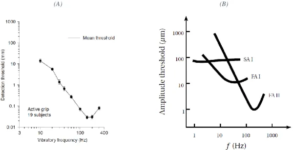
(20) Chapter 1.2: Haptic: Fooling The Human Perception of Touch. Thèse de Thomas Sednaoui, Lille 1, 2016 7. 1.2.3 Discrimination of frequencies As described in the previous section, the four human mechanoreceptors express different sensibilities to the multiple kinds of stimulus that we encounter every day. This extends to the discrimination of frequencies, which is fundamental to our perception of texture and handheld tool usage. A comprehensive measurement of the frequency response of each of the four mechanoreceptors was done by Johansson et al. in 1982 [18]. After a full adaptation of the finger to the indentation created by the stimulating probes, measures of frequency discrimination to a sinusoidal stimulation were done. (A). (B). Figure 1-8: Detection range of the mechanoreceptors in the human hand. (A) Shows the psychophysical threshold of detection reported by participants when subjected to the vibration of a 32 mm rod held in the hand. Adapted from [19] (B) Frequency range of Slowly Adapting I and Fast Adapting I, II mechanoreceptors [20].. As succinctly described in the previous paragraph, both SA receptors present a slow adaptation time with a bandwidth discrimination between 2 and 32 Hz. FA receptors present a more contrasted discrimination range. The Meissner Corpuscles (FA I) respond highly to stimulation from 8 to 64 Hz, while the Pacinian cells (FA II) have a maximum sensitivity between 64 and 400 Hz (but can detect vibration up to 1 kHz). Moreover, the signals measured by the FA II receptors are significantly more sensitive than the Meissner FA I, with a 20 to 30 dB difference. As summarized in [20] the maximum range of each mechanoreceptor can be seen in Figure 1-8 (B). It is interesting to note the similar behavior between the psychophysical detection curve in Figure 1-8 (A) which involves all the mechanoreceptors, and the mechanoreceptors’ response in (B). This is especially true for the FA II which are receptive on almost all the frequency range. 1.2.4 Creating Haptic Illusions The high concentration of multiple kinds of receptors, presented in the previous section, helps to infer the correct characteristic of the object being explored, even in the absence of complete data. In some cases, an incomplete input of sensory stream can cause tactile illusion with similar mechanisms as well-known optical illusions. All haptic feedback systems use this. © 2016 Tous droits réservés.. lilliad.univ-lille.fr.
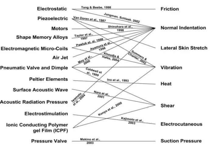
(21) Chapter 1: Literature Review. Thèse de Thomas Sednaoui, Lille 1, 2016 8. principle to generate “virtual” mechanical sensation for the user, that is not physically present around him.. Figure 1-9: Device creating a virtual curvature sensation for the user [21]. An example of such an illusion is the feeling of curvature that can be simulated using specific apparatus like in [22] [23]. An implementation of such a device is illustrated by Figure 1-9. The feeling of curvature is obtained by orienting the finger’s contact plate in function of the lateral position of the device. As previously mentioned, these illusions have been exploited for haptic feedback in multiple studies. Figure 1-10 describes the relation between the interaction mode being exploited and the Technology used to achieve the goal. Although the newest references are missing, this graph gives a good idea of the pallets of technologies available. A multitude of technologies and associated applications which were tested to provide new and useful haptics cues to users. Most of these technologies proved to be quite effective in their specific application cases, but failed to be sold industrially due to manufacturing difficulties, or size of the market concerned (this is the case of the device presented in Figure 1-9). Nevertheless, two interaction modes found a large success with the public: normal indentation (braille technologies) and vibrations (standard mobile device and game controller feedback).. © 2016 Tous droits réservés.. lilliad.univ-lille.fr.
(22) Chapter 1.2: Haptic: Fooling The Human Perception of Touch. Thèse de Thomas Sednaoui, Lille 1, 2016 9. Figure 1-10: Representation of haptic devices’ technologies and their interaction modes. Adapted from [24].. © 2016 Tous droits réservés.. lilliad.univ-lille.fr.
(23) Chapter 1: Literature Review. Thèse de Thomas Sednaoui, Lille 1, 2016 10. 1.3 TACTILE STIMULATION ADAPTED TO MOBILE DEVICES Most of the interaction modes presented in Figure 1-10 are uneasy to integrate with mobile applications due to the form factors of the technologies used. Such devices generally involve one or multiple bulky actuators and mechanical transmission. To alleviate this problem, other solutions have been developed with portable device and touch-screen in mind. This thesis focuses on the way to transmit tactile information to the user, and more specifically, texture illusion based tactile information. Ultimately, the goal is to integrate this type of tactile feedback into mobile devices to offer a more natural stimulation. Texture based stimulation is relying more on the FA II mechanoreceptors to imitate a real touch interaction (compared to simple low frequency vibrations which affect only the SA I and FA I). This section reviews the haptic systems applicable to the large touch screen now ubiquitous in all mobile devices. Today, only vibrating load stimulation has been implemented into consumer devices. However, texture reproduction presents a lot of potential and attracts the attention of industrials and consumers; if its industrialization issues find a solution, it will make its entry into the consumer market. 1.3.1 Growth of the haptic industry Haptic promises an increase in the comfort, ergonomics and precision in the use of touch based interfaces. With a growth already confirmed since multiple years, haptics applied to the new “Internet of Thing” connected devices promises to continue its expansion for the years to come. A forecast created by LuxResearch predicted an important inflexion point between 2014 and 2015 for the market of haptic touch screen [25]. But the market of haptic itself is larger than that, especially with the addition of upcoming virtual reality systems, its ecosystem of game controller, and professional design tools.. Figure 1-11: Market Forecast of the touch panel integrating haptic feedback technologies [25]. © 2016 Tous droits réservés.. lilliad.univ-lille.fr.
(24) Thèse de Thomas Sednaoui, Lille 1, 2016 11. Chapter 1.3: Tactile Stimulation Adapted to Mobile Devices. A shift in the technology used to create vibrations on mobile phones and tablets is already underway as can be seen in Figure 1-11 with the growth of piezoelectric actuators’ use. As for Friction based tactile interfaces, they are expected to enter the mainstream consumer market in less than 10 years with the introduction of electrostatic technology. 1.3.2 Vibrating Load The most common tactile stimuli used in mobile device today are based on the generation of low frequency vibration in the device held by the user. Multiple technologies are used to generate this effect in smartphones as can be seen in Figure 1-12.. Figure 1-12: Three types of vibrotactile actuators used in mobile devices [26]. The three mechanical solutions shown above return a strong, low frequency vibration to the hand of the user. Multiple companies such as Texas Instruments Inc™ (USA), AAC technologies Holdings Inc. (China), Densitron Technologies Pic (UK) and Immersion Corp (USA) share most of the world market. The first solution, known by the name of Eccentric Rotating Mass (ERM) is the most wellknown solution for haptic feedback in phone, tablets and gamepad controllers. It is implemented in most devices nowadays [27]. This technology uses a small electric motor connected to an asymmetric load to generate vibration in the handheld device. First used as a mean of force feedback in gaming application, it is nowadays implemented in complement with graphical user interface (GUI) in most touchscreens. ERM are the cheapest solution to integrate but present a relatively large form factor and the highest power consumption of the three technologies, with up to 5 % of the total smartphone consumption [26]. (a). (b). Figure 1-13: (a) ERM and LRA actuators respectively inside the iPhone4© and iPhone5© of Apple™ (b) Acceleration and deceleration pattern of ERM motors. © 2016 Tous droits réservés.. lilliad.univ-lille.fr.
(25) Chapter 1: Literature Review. Thèse de Thomas Sednaoui, Lille 1, 2016 12. The Linear Resonant Actuator (shown in Figure 1-13 (a)) is able to generate a similar amplitude of vibration than the ERM but presents the advantages of a smaller form factor and power consumption (only 2.5 % of the total energetic consumption for a normal smartphone day use [26]). LRA resonant mode of operation limits its frequency bandwidth to only a few hertz, which reduces the sensory modalities able to be excited by it. Moreover, its optimal resonant frequency tends to drift due to temperature and needs to be actively tracked by the smartphone for reliable tactile feedback. Piezo actuators are relatively new and start to be integrated into the last generations of devices. They present an extremely low form factor which makes them interesting for high tech smartphones. Their power consumption, while smaller than the other to generate a simple “click”, is similar to the ERM for longer “buzz” type of stimulation. 1.3.3 Texture based tactile feedback While the ease of integration of vibrating load made it quickly ubiquitous, this solution offers at best a limited feedback in the tactile sense; as a matter of fact, most of the feedback is perceived as a vibration of the whole hand and thus, uses the kinesthetic more than the tactile sense. On the other hand, users may be interested by a better tactile feedback, only perceived by the finger, and closely related to texture simulation. This subsection presents three technologies that offers the possibility to recreate the illusion of real textures. These solutions aim to modify the friction coefficient between the finger and the plate. 1.3.3.1 Surface Acoustic Wave One of the technological approaches is to apply Surface Acoustic Wave (SAW) to the medium. This approach was first described by [28]. Using piezoelectric material glued on the surface of the display, a SAW in the Megahertz range is generated on it. This makes it possible to temporally reduce the friction between a slider part, composed of a plate with small steel balls, and the medium where SAW is propagated. In later design, it was shown that the steel balls were not necessary if using a rigid slider (metal plate). Transparent device with an integrated LCD was also presented [29]. SAW are characterized by a wave frequency above 1 MHz and a vibration amplitude around 1 nm.. Figure 1-14: First implementation of SAW based haptic device with ball bearing under the slider [28].. © 2016 Tous droits réservés.. lilliad.univ-lille.fr.
(26) Chapter 1.3: Tactile Stimulation Adapted to Mobile Devices. Thèse de Thomas Sednaoui, Lille 1, 2016 13. This interface might be interesting due to its extremely simple potential integration into existing touch screen devices. Indeed, as the wave propagate on the surface of the substrate, it might be possible to fully glue the resonating glass on the screen underneath, improving the integrability and reliability. Besides, glasses incorporating the SAW principle as a mean to measure the position of the finger are already sold worldwide for their small form factor of detection and extreme robustness (use in ATM and diverse ticket vending machines). Combining both technologies would present a large reduction in cost and complexity. But the necessity of a sliding interface is extremely constraining for an application into a mobile platform, consumers would perceive this interface as a step backward in term of integration and ease of use. 1.3.3.2 Increasing the Friction: The Electrovibration stimulation Another way to generate tactile information for the user was found first by Mallinckrodt in 1954 [30] whom reported: “... that dragging a dry finger over a conductive surface covered with a thin insulating layer and excited with a 110 V signal, created a characteristic rubbery feeling” Applying a voltage between a surface and the finger with a small isolator in between creates an attractive force (shown in Figure 1-15). While this force is not perceivable by the user directly, its consequence on the friction between the finger and the surface is relevant on the haptic point of view, especially when the friction is modulated as the finger is sliding above the surface in an exploratory movement [31]. This solution also allows for multi-touch solution [32]. The main drawback is the need for a high voltage (in the order of the kV) with a thin insulation layer prone to abrasion by repeated use [30]. Multiple laboratories and companies are nonetheless involved in improving and commercializing this technology. Recently, a new model has been proposed to explain the frequency dependence of the electrostatic force [33] and the technology has been merged with another one to improve haptic feedback [34].. Figure 1-15: Principle of an electrovibration haptic device integrated into a transparent screen. ITO is a thin-film conductive and transparent material used to propagate the charge across the whole screen of the device. SiO2 is also a thin-film but acts as an insulator and can be deposited in an extremely small stack, improving the friction increase effect [31].. © 2016 Tous droits réservés.. lilliad.univ-lille.fr.
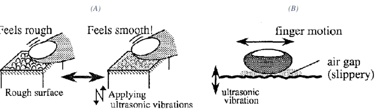
(27) Chapter 1: Literature Review. Thèse de Thomas Sednaoui, Lille 1, 2016 14. However, even with this constraint, startups have been created in recent years with the ambitious goal of pushing this technology to the mass consumer as part of our standard smartphones: Tanvas™ and Senseg™ (recently bought by the Chinese phone maker O-Film), are currently selling demonstrators and developments kits as seen in Figure 1-16. (A). (B). Figure 1-16: Development Kit and showcases by startups involved in electrostatic stimulation (A) Shows the dev-kit tablet developed by Senseg™, company recently bought by the Chinese phone maker O-Film (B) Showcase application by Tanvas™ in WorldHaptics 2016. It must be noted that despite the progress made by these new companies, the electrostatic stimulation still faces large challenges. The large cost of the thin-film deposition (both ITO and SIO2 shown in Figure 1-15) and the fear of the high voltage close to the skin makes it difficult to sell to the mass market. 1.3.3.3 Decreasing the Friction: The Ultrasonic Lubrication stimulation Another way to control the friction between the finger and a surface relies on Ultrasonic Lubrication (UL). This effect, applied to the human hand, was first described by T. Watanabe and S. Fuikui in 1995 [35]: when a planar surface is put under ultrasonic vibration, a change in the dynamic friction coefficient between the finger and the surface can be observed. The dynamic friction coefficient is then shown to be reduced more and more for an increase of the amplitude of vibration. The first theory proposed to explain the phenomenon is the squeeze film effect, as first described by O. Reynolds (1842-1912) [36]. Similarly to friction free air-table, a local overpressure is created between the surface of two objects, which then reduces the measured dynamic friction coefficient between these objects [37]. While a porous material and a compressor cannot be implemented in a portable device, squeeze film effect showed that it can compress the air locally under the finger by applying an ultrasonic vibration to the device. As seen in Figure 1-17, a rough surface is perceived by the participants as smooth when an ultrasonic vibration is applied to the surface. These first studies use a frequency of vibration just above hearing range (around 20 kHz) but not too large, to limit the complexity of actuation and control.. © 2016 Tous droits réservés.. lilliad.univ-lille.fr.
(28) Chapter 1.3: Tactile Stimulation Adapted to Mobile Devices. (A). Thèse de Thomas Sednaoui, Lille 1, 2016 15. (B). Figure 1-17: T. Watanabe & S. Fuikui description of ultrasonic vibration applied to haptic feedback. The methodology was then explored again by M. Biet [38] in 2007, to put a full copperberyllium surface under vibration by taking advantage of a resonant mode of vibration. Actuated by a matrix of Lead Zirconium Titanate piezoelectric ceramics, as seen in Figure 1-18, the technology was capable to reduce strongly the friction coefficient across a large area. (A). (B). Figure 1-18: Copper-beryllium ultrasonic haptic device. (A) Surface explored by the user, friction is reduced when the plate is under vibration. (B) Matrix of PZT actuators used to put the plate under vibration. From these first studies, multiple iterations and optimizations have been proposed through the years. These studies will be described in details in the following section.. © 2016 Tous droits réservés.. lilliad.univ-lille.fr.
(29) Chapter 1: Literature Review. Thèse de Thomas Sednaoui, Lille 1, 2016 16. 1.4 TACTILE STIMULATION MEDIATED BY ULTRASONIC LUBRICATION EFFECT Ultrasonic Lubrication presents multiple advantages compared to other tactile stimulation techniques. First, it provides a strong tactile stimulation felt directly by the fingertip without any additional slider, as for SAW. Second, there is no issue with large voltage close to the skin since the piezoelectric actuators are placed under the surface to explore and can be supplied by low voltage. This section first presents the evolution in the design of UL stimulation since the discovery of the phenomenon in 1995. A second part then focuses on methods developed to help with the design and development of such a device. 1.4.1 Development of the UL based tactile stimulation The following subsection describes in details the principle of UL stimulation and the optimizations done since its inception. 1.4.1.1 First observation of the UL effect on Human fingers As first defined by T. Watanabe in [35], UL generates a tactile sensation by temporarily changing the perception of the state of the surface, from rough to totally “smooth”. In his experiment, a steel beam is led in vibration at its extremities by two Langevin actuators. At a frequency of 77kHz, a resonant flexion of the beam up to 2µm is observed. A participant was then asked to displace his finger across the beam. Participants systematically noticed a difference in the perceived roughness of the beam between the vibrating and non-vibrating states. The limits of this effect were then quantified by presenting beam of different inherent surface roughness. A seen in Figure 1-19, they found that for a higher roughness of the beam a larger amplitude of vibration was necessary to reach a “smooth” perception of the surface by the participants. (A). (B). Figure 1-19: Watanabe Experiment in [35]. (A) Experimental setup with its two Langevin actuators. (B) Perception of the roughness of surface in function of the amplitude of vibration of the beams. Four beams of different inherent roughness are presented.. Subsequent measures with different modes of resonance of the beam showed that the change of roughness perception does not occur under a frequency of at least 10kHz.. © 2016 Tous droits réservés.. lilliad.univ-lille.fr.
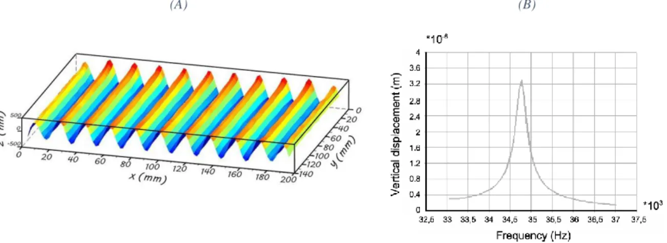
(30) Chapter 1.4: Tactile Stimulation Mediated by Ultrasonic Lubrication Effect. Thèse de Thomas Sednaoui, Lille 1, 2016 17. In this first paper Watanabe proposed the mechanism of “squeeze film” to explain the reduction of the dynamic friction coefficient observed between the beam and the participants’ fingers. The squeeze film effect is well known in industry to provide a “dry” lubricating process; one of the most commonly found application is its use in hard-drives to provide a self-bearing between the reading head and the disks’ surface [39]. In this application, the air film is created by the fast tangent speed of the reading head compared to the disk’s surface. Squeeze film model will be presented in more details in Chapter 2. 1.4.1.2 Evolution of Ultrasonic Lubrication based displays Since this first experimental proof of the UL effect by Watanabe, multiple prototypes and demonstrators have been built. In most cases, a square surface is put under vibration at an inaudible frequency (above 20kHz) with the help of a resonant mode. In order to present an homogeneous effect across the surface, a standing wave mode of vibration is generally preselected by simulation before building the device (see Figure 1-20 A). The vertical displacement achievable by this method is highly dependent on the precision of the excitation frequency as seen in Figure 1-20 (B). (A). (B). Figure 1-20: Simulation of the dynamics of the resonating plate before its creation. (A) Longitudinal lamb wave, propagating in the direction of the long axis of the rectangular plate. (B) Results of an harmonic analysis: absolute vertical displacement of a surface point in function of the frequency (ANSYS software®), adapted from [40]. Using these methods, the first tactile feedback devices were proposed by Windfield et al. in 2007 [41]. This new tactile interface called the Tpad was composed of a circular piezoelectric actuator glued to a 25mm diameter glass that can be touched and explored by the user. The vibration can be modulated in function of the position of the finger which enables the creation of virtual texture and tactile patterns. Following work increased the size of the device and added LCD underneath [42] [43] [44].. © 2016 Tous droits réservés.. lilliad.univ-lille.fr.
(31) Thèse de Thomas Sednaoui, Lille 1, 2016 18. Chapter 1: Literature Review. Figure 1-21: Tpad created by Windfield et al. at Northwestern University [41]. Another important study was performed in the L2EP in University Lille1 by M. Biet under the supervision of B. Semail; a copper-beryllium plate with piezoceramic elements, attached under it in a matrix pattern, can generate strong tactile sensation to the user [38] [40]. Subsequent developments performed in the L2EP made possible the integration work of the technology in a mobile package and in multiple form factors [45] [46] [47]. Follow up work was presented implementing a transparent device with a LCD underneath [46], shown in Figure 1-22. These works lead to the design of the Stimtac®, an integrated haptic device [48] [49]. (A). (B). Figure 1-22: Transparent UL tactile stimulator based on the Stimtac® [46]. (A) Schematics of the resonant tactile stimulator with the LCD underneath in Blue. Forces sensors (Green Cones) are used to measure the position of the fingertip (B) The final assembly of the tactile stimulator in operations.. The finger position in these devices is inferred by reading 4 strain gauges on the sides of the screen. A single or a double row of piezo-actuators on the side of the transparent interface is used for actuation. Finally, in recent designs, some of the piezo-ceramics are used as sensor (the bending constraint generates an electric field that can be measured). To increase the repeatability of the haptic signal transmitted, the amplitude and phase data can then be used to close amplitude and frequency control loops with a microcontroller (MCU) [50]. To be complete on UL devices, it may be noted that other institutes have worked on the analytic modeling and Finite Element Modeling of lamb wave propagation in resonator to induce friction control [51] [52] [53] [54] [55].. © 2016 Tous droits réservés.. lilliad.univ-lille.fr.
(32) Chapter 1.4: Tactile Stimulation Mediated by Ultrasonic Lubrication Effect. Thèse de Thomas Sednaoui, Lille 1, 2016 19. 1.4.1.3 Optimizations and coupling of Ultrasonic Lubrication with other mode of stimulation The concept of Ultrasonic Lubrication has been used in combination with other technologies to create enhanced haptic feedback effect. The first coupling was presented by Erik C. Chubb in 2009 with the ShiverPad: a device capable of controlling the shear force on a bare finger. Using an UL TPad developed by the same laboratory, coupled with a lateral linear actuator, the authors could generate a force at the tip of a static bare finger in contact with the UL surface. As seen in Figure 1-23, the UL effect is only activated when the surface is moved in one direction, resulting in a net force on even an immobile finger. This effect was then optimized in subsequent study to reduce the perceivable artifacts [56]. (A). (B). Figure 1-23: The ShiverPad proposes a solution to generate forces at the tip of a static finger [57]. (A) Friction reduction effect of UL is applied synchronously with the lateral vibration to generate a force (B) Use of a TPad connected to a lateral linear actuator.. A second notable coupling has been proposed by F. Giraud in [34]. In this study the friction reduction effect of UL is combined with the friction increase effect generated by electrostatic stimulation presented in section 1.3.3.2. Being this concept is the hope that, by combining these technologies, it might be possible to generate an enhanced friction modulation effect (with even more perceivable differences between the states of high and low friction). Later validated by D. Mayer in [58], an in-depth comparison of both effects showed that despite its slowest modulation dynamics, UL modulation provide a larger range of stimulation compared to electrostatic displays, going from a coefficient of friction as high as 1 to frictionless contact. The coupling of both effects on the same devices would potentially be able to offer the best of both world, strong and high frequency friction modulation. 1.4.2 Design and Optimization of an Ultrasonic Lubrication plate The UL devices presented in this chapter and in the rest of this thesis were designed using similar methods. This section explores these methods to provide an understanding of the creation process involved in their development.. © 2016 Tous droits réservés.. lilliad.univ-lille.fr.
(33) Thèse de Thomas Sednaoui, Lille 1, 2016 20. Chapter 1: Literature Review. The fundamental goal of the procedure is to create a flat rectangular plane of the required dimensions that presents a resonant vibration across its surface. When building experimental devices, our choice goes to standing wave mode of vibration. Specifically, a Lamb waves presenting a homogeneous maximum amplitude of vibration across the whole surface is selected. Lamb waves, are elastic waves whose particle motion lies in the plane that contains the direction of wave propagation and the plate normal (the direction perpendicular to the plate). 1.4.2.1 Iterative Simulation Method The first step of the design is to model the geometry of the plate and the piezoelectric actuators with a Computer Assisted Design (CAD) tool (Especially for complex geometries). The final geometry can then be transferred to finite element software (Salome Meca®, Comsol®, ANSYS® or Coventor®). When the geometry has been designed, and meshed with the correct material properties (Figure 1-24 (a)), it is then possible to calculate the Eigen frequencies for the range of frequencies of interest (typically between 25 kHz to generate the lubrication effect and to be above audio, and 100 kHz for ease of control). The size of the meshing has a large effect on the accuracy of the FEM simulation, proper care should be taken to make sure a meshing small enough is selected as in Figure 1-24 (b). (a). (b). Figure 1-24: (a) Meshing of a complex glass plate supporting piezoelectric ceramic actuators and a second layer of glass touchscreen on the top (b) Convergence of the meshing to determine the resonant mode of vibration [59].. Once simulated, the vibration deformation pattern for each resonant frequency can be displayed and the proper Lamb wave can be selected. One important factor in this choice is the distance between the nodal lines. Devices with large spacing between nodal lines present a noticeable decrease of the friction reduction when the finger is above the nodal lines. A distance inferior to the width of a fingertip is chosen to avoid these effects (usually inferior to 8 mm [38]). Once a specific resonant mode is selected, two factors need to be optimized before the geometry is chosen:. © 2016 Tous droits réservés.. lilliad.univ-lille.fr.
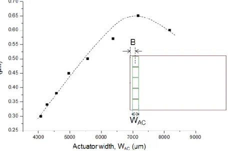
(34) Chapter 1.4: Tactile Stimulation Mediated by Ultrasonic Lubrication Effect. -. -. Thèse de Thomas Sednaoui, Lille 1, 2016 21. The presence of parasitic modes of vibration too close to the frequency of the selected Lamb wave needs to be checked. These parasitic modes might get excited during the experiment due to a local variation of damping caused by the user’s finger. These parasitic modes can reduce the electro-mechanical coupling and thus the maximum amplitude of vibration which then affects negatively the friction coefficient reduction. Typically, these modes of vibration present crisscrossing nodal lines across the whole surface and non-homogeneous amplitude of vibration. The second point to take into consideration is the homogeneity of the standing wave amplitude of vibration across the surface. A non-homogeneous wave will automatically create zones of higher and lower friction reduction for a given excitation.. As described by F. Casset in [60], an iterative optimization using harmonic simulations is used to find the best position for the actuators. A voltage gradient is applied across the virtual electrode and a mechanical damping parameter is used to find the maximum displacement of the substrate. This damping can be estimated using measures on a device with similar properties as in [61]. If an arbitrary damping parameter is chosen, only relative information can be extracted from simulation. Once calculated, the geometry and position of the piezoelectric actuators is changed slightly in an iterative approach. A new simulation of the frequency region around the selected mode of vibration is then recalculated to evaluate the effect of the changed actuators’ location (Figure 1-25). This last procedure is repeated until the resonant mode presents a maximum displacement of the substrate, while keeping a good homogeneity and distance with the parasitic modes.. Figure 1-25: Optimum actuator width for a 110 × 65 mm² glass plate determined using harmonic simulations. [61] [60]. © 2016 Tous droits réservés.. lilliad.univ-lille.fr.
(35) Thèse de Thomas Sednaoui, Lille 1, 2016 22. Chapter 1: Literature Review. 1.4.2.2 Analytic analysis While this iterative simulation approach gives good results, an analytical solution would improve the time and precision of the design and optimization of such a system. This analytical approach was first described by M. Biet in [38]. To determine the wavelength necessary for the resonant actuation of the haptic plate, she developed models of the vibration to reduce the complexity of the calculus. The simplified system is defined as a stack of piezoelectric material and the vibrating substrate. By reducing the study to a single half wavelength, it is possible to consider the plate supported at its extremities (as seen in Figure 1-26 (a)). The resolution of the system is based on the study of the static and dynamic deformation of the stack when considering uniquely the flexion mode of movement. The half wavelength beam displacement is then found by: 𝑤𝑑𝑦𝑛. −3𝑑31 𝑉𝑧 𝜆𝑜𝑛𝑑𝑒 2 1 − 2𝑓0 = 𝑄𝑚 ) ( ) ( 2 16ℎ𝑝 2 1 − 3𝑓0 + 3𝑓02. (1). Where 𝑤𝑑𝑦𝑛 is the maximum displacement of the plate. 𝑄𝑚 is the quality factor of the piezoelectric ceramic, with 𝑑31 its piezoelectric coefficient and ℎ𝑝 its thickness. 𝑓0 is the ratio between the piezo-ceramic and the substrate. Finally, 𝑉𝑧 represents the voltage supply necessary to obtain a displacement of 𝑤𝑑𝑦𝑛 . (A). (B). Figure 1-26: (a) Simplified part of the half wavelength beam. Its bending is the effect of the piezoelectric material at the bottom. (b) Calcul of the curvature in function of the half wavelength for a voltage supply of 15 V AC. [38]. In the model, Biet uses a Copper-Beryllium plate with a 2 mm thickness on which are glued 1 mm piezoelectric ceramics. For an excitation of 15 V AC, it was then possible to calculate the evolution of 𝑤𝑑𝑦𝑛 in function of the wavelength as presented in Figure 1-26 (b). Increasing the distance between the nodes improve quickly the achievable amplitude for a given voltage. However, this distance cannot be increased too much, otherwise the user will start to feel the presence of the nodal lines. As said before, an 8 mm half wavelength is usually chosen to reduce this effect.. © 2016 Tous droits réservés.. lilliad.univ-lille.fr.
(36) Chapter 1.4: Tactile Stimulation Mediated by Ultrasonic Lubrication Effect. Thèse de Thomas Sednaoui, Lille 1, 2016 23. Analytical models to help with the piezo-ceramics placement optimization have been extensively studied by C. Nadal in 1 dimension [62]. Similarly, F. Bernard studied the placement of thin-film piezo-ceramics on a transparent surface in 2 dimensions using an energetic approach Figure 1-27.. Figure 1-27: Analytic calculation of the Lateral and Normal displacement of a simulated glass of 0.5mm for a resonant mode at 19652Hz. [59]. © 2016 Tous droits réservés.. lilliad.univ-lille.fr.
(37) Chapter 1: Literature Review. Thèse de Thomas Sednaoui, Lille 1, 2016 24. 1.5 CONCLUSION Up to recently, research in finger and hand biomechanics was motivated by medical reasons. But with the rapid diffusion in the consumer market of devices including basic haptic rendering, these problematics came back to the frontline of research and extended their range of applications. As a matter of fact, understanding the mechanical perception of environment by human is critical for a correct development of good haptic illusion effects. The market of haptic is still expanding quickly with the multiplication of touch based devices and the explosive growth of virtual reality systems. It is estimated that it will double in the coming years to reach 30 billion dollars. Even with this large expansion, no device currently sold can recreate our most natural tactile interaction, that is the perception of textures and roughness. Ultrasonic Lubrication presents a unique opportunity to solve this absence by the modulation of its friction reduction effect. As shown in this chapter, multiple companies have tried to push for the adoption of tactile and texture rendering on mobile platforms. The fact that none have been successful until now, despite the strong interest from the consumers, is due to the show-stopping constraints of all the possible technologies. All the possible constraints: Fear and durability in the case of Electrostatic, bad ergonomics for SAW and integration constraints for ultrasonic lubrication. Even with its issues, UL stimulation exceptionally strong feedback, and comparatively simple constraints (Engineering problems), has the best hopes to present a new standard of tactile stimulation. As part of the European PROTOTOUCH Project, the objective of this thesis was to iterate on the design and development of UL devices to provide a better understanding of the conditions necessary to create an industrially exploitable effect. To this end, the next chapter will measure precisely the effects of UL modulation on the dynamic friction coefficient to validate the previously proposed models. Using this better understanding of the phenomenon, improved UL tactile stimulator design will be proposed in chapter 3. Finally, the last chapter will use these improved devices to study control scheme, aiming to reduce the relatively high power consumption of UL devices.. © 2016 Tous droits réservés.. lilliad.univ-lille.fr.
(38) Chapter 1.5: Conclusion. Thèse de Thomas Sednaoui, Lille 1, 2016 25. 2 PHYSICAL CHARACTERIZATION OF THE INTERFACE BETWEEN HUMAN FINGERS AND AN ULTRASONIC VIBRATING SURFACE. Summary 2 Physical characterization of the interface between human fingers and an ultrasonic vibrating surface 25 2.1. Objectives: Creating a set of design guidelines for the designers of UL displays. 26. 2.2. Description of the methodologies. 28. 2.2.1. Design and control of the UL devices specialized for tribological measures. 28. 2.2.2. Tribometric approach to measure the dynamic friction coefficient. 29. 2.3. 34. 2.3.1. Objectives of the Experiment. 34. 2.3.2. Experimental Setup. 34. 2.3.3. Evaluation of the Friction Reduction Results. 38. 2.3.4. Conclusion. 42. 2.4. Influence of the Resonant Frequency on Ultrasonic Friction Reduction Devices. 43. 2.4.1. Objectives of the Experiment. 43. 2.4.2. Experimental Setup. 44. 2.4.3. Evaluation of the Friction Reduction Measures. 46. 2.4.4. Conclusion. 49. 2.5. Comparison of measured data with existing models. 51. 2.5.1. Historical background on the Ultrasonic Lubrication. 51. 2.5.2. Evaluation of the Squeeze Film model. 51. 2.5.3. Evaluation of the Intermittent Contact Spring Model. 55. 2.5.4. Conclusions. 63. 2.6. © 2016 Tous droits réservés.. Asymptotic limit of achievable reduction of the friction coefficient. List of Requirements for an ULD and Design Rules. 64. 2.6.1. Amplitude of Vibration. 64. 2.6.2. Frequency of the resonant mode. 64. 2.6.3. Rise time of the Vibration Amplitude. 64. 2.6.4. Conclusion. 65. lilliad.univ-lille.fr.
Figure
![Figure 1-4: The microneurographic technique. An electrode is implanted into the nervous nerve bundle to find a single afferent [7]](https://thumb-eu.123doks.com/thumbv2/123doknet/3705375.110215/17.892.140.760.492.802/figure-microneurographic-technique-electrode-implanted-nervous-bundle-afferent.webp)
![Figure 1-12: Three types of vibrotactile actuators used in mobile devices [26]](https://thumb-eu.123doks.com/thumbv2/123doknet/3705375.110215/24.892.148.740.344.504/figure-types-vibrotactile-actuators-used-mobile-devices.webp)
+7
![Figure 1-14: First implementation of SAW based haptic device with ball bearing under the slider [28]](https://thumb-eu.123doks.com/thumbv2/123doknet/3705375.110215/25.892.147.749.910.1095/figure-implementation-saw-based-haptic-device-bearing-slider.webp)

![Figure 1-23: The ShiverPad proposes a solution to generate forces at the tip of a static finger [57]](https://thumb-eu.123doks.com/thumbv2/123doknet/3705375.110215/32.892.120.764.350.643/figure-shiverpad-proposes-solution-generate-forces-static-finger.webp)
Documents relatifs