HAL Id: inserm-00159159
https://www.hal.inserm.fr/inserm-00159159
Submitted on 2 Jul 2007
HAL is a multi-disciplinary open access
archive for the deposit and dissemination of
sci-entific research documents, whether they are
pub-lished or not. The documents may come from
teaching and research institutions in France or
abroad, or from public or private research centers.
L’archive ouverte pluridisciplinaire HAL, est
destinée au dépôt et à la diffusion de documents
scientifiques de niveau recherche, publiés ou non,
émanant des établissements d’enseignement et de
recherche français ou étrangers, des laboratoires
publics ou privés.
Intrinsic 2D/3D registration based on a hybrid
approach: use in the radiosurgical imaging process.
Maximilien Vermandel, Nacim Betrouni, Jean-Yves Gauvrit, David Pasquier,
Christrian Vasseur, Jean Rousseau
To cite this version:
Maximilien Vermandel, Nacim Betrouni, Jean-Yves Gauvrit, David Pasquier, Christrian Vasseur, et
al.. Intrinsic 2D/3D registration based on a hybrid approach: use in the radiosurgical imaging process..
Cellular and Molecular Biology, R. Wegmann, 2006, 52 (6), pp.44-53. �inserm-00159159�
59
I
IN
NT
TR
RI
IN
NS
SI
IC
C
2
2D
D/
/3
3D
D
R
RE
EG
GI
IS
ST
TR
RA
AT
TI
IO
ON
N
B
BA
A
SE
S
ED
D
O
ON
N
A
A
H
HY
YB
BR
RI
ID
D
A
AP
PP
PR
RO
OA
AC
CH
H:
:
U
US
SE
E
I
IN
N
T
TH
HE
E
R
RA
AD
D
IO
I
OS
SU
UR
RG
GI
IC
C
AL
A
L
I
IM
MA
A
GI
G
IN
NG
G
P
PR
RO
OC
CE
ES
SS
S.
.
MAXIMILIEN VERMANDEL
1,2, NACIM BETROUNI
1, 2, JEAN-YVES GAUVRIT
3,
DAVID PASQUIER
4, CHRISTIAN VASSEUR
5and JEAN ROUSSEAU
1, 21
Inserm, U703, Lille, 59037, France;
2
University of Lille 2, UPRES EA 1049, Lille, 59800, France;
3
CHRU de Lille, Department of Neuroradiology, Lille, 59037, France;
4
Department of Radiotherapy, O. Lambret, Lille, 59020, France;
5
CNRS, UMR 8146, Lille, F-59037, France
1Inserm U 703 - Institut de Technologie Médicale, Pavillon Vancostenobel, CHRU de Lille - 59037 Lille Cedex - France
Tel: 333 20 44 67 21; Fax: 333 20 44 67 15 ; E-mail: m-vermandel@chru-lille.fr
Abstract – During the latest years, numerous methods of multimodal image matching have been developed. Associated with
medical imaging, these developments make it possible to match images using intrinsic data, as anatomical data, instead of external referential, as stereotactic frames. Thus, the use of intrinsic registration considerably increases possibilities in medical image analysis. Unfortunately, these techniques mostly remain in the research field and are rarely used in clinical daily practice. In this paper, we present a method for matching projective imaging (2D, radiography, angiography…) and tomographic imaging (3D, Magnetic Resonance Imaging, Computed Tomography). Furthermore, we propose a radiosurgical application for Arteriovenous Malformation (AVM). Radiosurgery planning for the treatment of AVM requires multiple image acquisitions in multimodality to define the irradiation target and to compute the dosimetry. All the planning images are acquired with a stereotactic frame. We describe in this paper the image registration technique that we propose to include diagnostic images in the planning process and the different steps required to validate our approach. In the current state, the results obtained do not enable us to replace the conventional technique due to the accuracy expected, but the analysis of the results shows that improvements of the protocol would make this application finally operational.
Key-words: Neurosurgery, Gamma Knife, 2D / 3D Registration, Image Matching, MRA, DSA, Image Guided Surgery
INTRODUCTION
Recent decades have seen the emergence of new
medical
imaging
techniques,
such
as
the
Computerized Tomography (CT) scanner, Nuclear
Medicine (NM), Magnetic Resonance Imaging
(MRI) and Positron Emission Tomography (PET).
All these modalities have favoured the progressive
use of digital imaging to such an extent that even the
oldest imaging modality, radiology, now uses digital
sensors such as brightness amplifiers and flat CCD
sensors. The increasing acquisition speed, digital
storage and the variety of modalities are gradually
changing the daily working practices of physician,
who have access to a large amount of data to refine
their diagnoses. This profusion of images has given
rise to several disciplines such as the management of
image flows (storage, access, etc.) and
post-treatment. Post-treatment ranges from image
processing, improving image quality, quantification,
classification, to registration and image fusion. The
registration firstly became necessary in order to fuse
the images coming from different modalities and
whose information was complementary (e.g.
morphological and functional images). Then, the
field of application became open to more surgical or
interventionist practises. For example, neurosurgery
required the combined use of morphological images,
defining the pathological areas, and activation
images, defining the brain's functional areas. The
work described in this paper concerns the planning
for the treatment of Arteriovenous Malformations
(AVM) in radiosurgery. We present an intrinsic
registration methodology that does not use any
external reference and can be used to fuse
radiological images of the arteriovenous system (the
2D X-ray Angiography (XRA) image) and Magnetic
Resonance Angiography images (MRA, 3D). We
first define the terms and definitions used in this
paper. Then, after a brief description of imaging and
radiosurgery methods, we present the various
existing registration techniques and those developed
by the authors to fuse XRA and MRA images.
Finally, we describe the validation protocol that has
been developed and some preliminary results.
Terms and definitions
Registration –
As a general rule, registration (1,2)
can be defined as the search for a mathematical
relation between two data sets in order to be
observed in a common space. For example, rigid
image
registration
is
the
search
for
the
60
transformation T, combining rotation and
translation, allowing the transition from a
floating image F to a reference image R. In
this case, each image represents the same
object but, when the acquisition conditions
are different, a transformation has to be
applied to image F so that it can be
superimposed on image R.
The image registration can be performed using
two procedures:
using an external reference whose geometry is
known (i.e. stereotactic frame, fiducial markers).
using the similarities existing between the
images, only the anatomical content is used for
registration, this is a so-called intrinsic
registration. Two methods of computation must
be highlighted:
o feature-based
approach
which
uses
geometrical features extracted from image
data such as surface, contour…
o intensity-based approach which uses a
statistical dependency between images
according to grey-level.
Image fusion –
Image fusion is often used
with
the
aim
to
view
two
images
simultaneously. Once the registration has been
performed,
the
two
images
can
be
superimposed.
They
can
be
viewed
simultaneously in the same space by using
various algorithms (3) (transparency, pixel
based fusion, segmented based fusion, etc.) .
MATERIALS AND METHODS
Radiosurgery
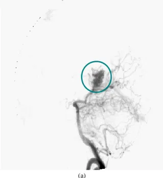
AVM consists of a disease in the vascular network, one of the commonest malformations being the angioma (Fig. 1).
(a)
Fig. 1a Arteriovenous Malformation, from X-Ray view.
(b) Fig. 1b From MRI view.
An angioma is a network of fine secondary and parasitic blood vessels (nidus), connecting the arterial and venous systems and thereby causing disruption to cerebral blood supply. Intracranial AVMs are usually diagnosed by a diagnostic XRA visualizing the cerebral blood vessels. Depending on its size, its treatment may require a one shot irradiation delivered to the patient by radiosurgery (4,5). This treatment requires the combined use of vascular and anatomical images such as XRA and MRI. These two exams are acquired using a stereotactic frame fixed to the patient's head. The frame is required to locate the lesion within the space of the Treatment Planning System (TPS). Once the AVM has been located within the TPS, the position of the irradiation beams are calculated taking into account sensitive organs such as the optic chiasma, eyes and brain stem. The aim of this paper is to present a new methodology for locating AVM in the TPS space using diagnostic XRA instead of framed XRA.
Our method is illustrated here through the Gamma Knife radiosurgery but the methodology is also valid for other radiosurgical techniques. The Gamma Knife mainly consists of a radiation unit (Fig. 2a) containing 201 60Cobalt sources (30Ci at delivery, radioactive half-life 5.27 years) and a moveable helmet with a choice of four collimators of 4, 8, 14 or 18mm diameter. The 201 orientations that are available on the Gamma Knife, when no collimator is obstructed by a plug, are shown in Fig. 2b.
Fig. 2 (a) the Gamma Knife and principle of irradiation with the gamma knife using multiple photon beam, (b) shows all the available beams, for a treatment only few of them are kept, all the other are “plugged”. The aim of planning treatment is to irradiate the target volume with a more suitable dose, while sparing the healthy surrounding structures. It must be achieved with the accuracy of about one millimetre. The coordinates of the isocentres are determined on the basis of the dimensions, the shape and the location of the lesion identified on the images. Normally, several target centres are needed to cover the entire volume, which involves repositioning the patient by an electromechanical system
Intrinsic 2D/3D registration based on a hybrid approach: Use in the radiosurgical imaging process.
61
The Gamma Knife requires the use of a stereotactic system (6) (Fig. 3 and 4) to locate the target during irradiation. The stereotactic frame is screwed onto the external surface of the patient's head and remains fixed to the patient from the imaging exams to the treatment.
Fig. 3 Leksell stereotactical frame (or “N” frame)
used for localization.
Fig. 4 MRI slice of the frame and radiological view of the frame, the white arrows designate the Leksell frame (the “N” frame on the slice, and markers on the XRA).
Radiosurgery of AVMs requires planning using anatomical and vascular images. The anatomical images are acquired using CT and MRI. The vascular images are acquired by X-ray angiography (XRA), which provides images of the cerebral vascularisation with an excellent spatial and temporal resolution. XRA is used as the reference for locating the target. Angiography technique is particularly invasive since it requires the use of a catheter that is guided from the femoral artery to the carotid and a large amount of contrast agent has to be injected. The acquisition (up to 10images/s) provides an indication of the arterial and venous blood flow times (Fig. 5).
Fig. 5 Dynamic sequence in XRA where 1 is the arterial time and 4 is the venous time (2 and 3 are intermediate).
The bone structures are eliminated by subtracting the first image of the series (in which only the bone structures appear) from the images with the contrast medium (Fig. 6), hence the term Digital Subtracted Angiography (DSA).
Fig. 6 Digital subtraction, where (a) is the image without contrast agent, only the skull is visible, (b) is the image with contrast agent, (c) is the image where the skull has been removed.
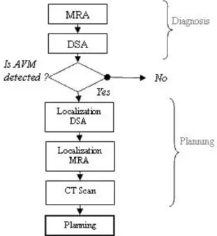
The standard sets of images needed for the treatment of the disease are shown in Fig. 7. The disease is diagnosed by a standard DSA (without stereotactical frame), but, for the planning, a second DSA is acquired with the locating stereotactic frame in position as well as MRI and CT. We propose here to ease the imaging procedure by suppressing the framed DSA acquisition (7).
Fig. 7 Standard sequence of imaging for radiosurgery, diagnosis is done using MRA and DSA. If AVM is detected, localization DSA, MRA and CT scan are acquired to plan the treatment.
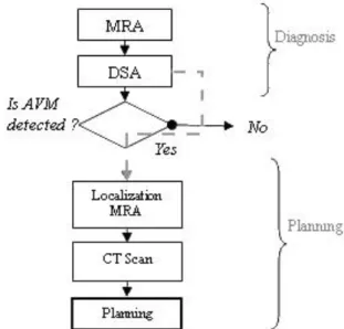
The needed images flow would become as in Fig. 8 where a Magnetic Resonance Angiography (MRA) is taken alongside the MRI. This MRA registered with the DSA, enables to navigate between MRA and DSA (MRI and MRA being in the same
62
reference space). Note that the MRA acquisition is not a constraint of the proposed method because it is increasingly requested by neuro-radiologists for post-treatment follow-up. Generally, the acquisition by Magnetic Resonance Angiography relies on two techniques. The first requires the injection of gadolinium, a substance that locally modifies magnetic susceptibility. The second is based on the blood kinetics in the axial plane; this technique is called Time Of Flight (TOF).
Fig. 8 Proposed flow sequence of imaging for radiosurgery, diagnosis is done using MRA and DSA. If AVM is detected, localization MRA and CT scan are acquired to plan the treatment, diagnostic DSA is reused for planning.
In summary, the use of an efficient DSA/MRA registration method should provide relationships for pairing two projections (e.g. anterior or lateral views). Using paired views enable to determine a 3D point in the MRA space from the corresponding 2D coordinates on the projections. As MRA exams intended for radiosurgery are framed, from a couple of 2D points in the DSA we finally determine a point in the treatment reference system.
Image acquisition
MRA images were acquired on a Siemens Magnetom VisionMRI scanner. (see table 1) and DSA images were acquired on a Philips Allura V5000 angiograph (see table 2).
Table 1 MRA images parameters.
Gadolinium
MRA TOF
Sequence Type injected 3D Time Of Flight
Magnetic Field 1.5T 1.5T
Slice thickness 0.5mm 0.7mm
Plan Face Transverse
TR 6.8ms 37ms
TE 2.3ms 7.2ms
Row and Col
PixelSize 0.5mm 0.5mm
Number of Slices per
volume 130 80
Resolution 512x512 512x512
Table 2 DSA images parameters.
Sequence Type Multiframe
acquisition
Source Intensifier Distance variable
Paired projection no
Row and Col PixelSize variable Number of projections per exam 24
Resolution 1024x1024
Registration techniques
The aim of registration methods between volume and projections is to determine the best position of the tomographic slices in the space of the planar modality (Fig. 9).
Fig. 9 2D/3D registration example which illustrates the research of the correct position of 3D data (MRA slices) in the projection space (DSA).
The 2D/3D registration may appear to be relatively simple if there is an external reference frame, such as Leksell frame, that is firmly fixed to the object and readily identifiable in each imaging modality. The problem is much more difficult if there is no frame. The only possible relation becomes the object itself, which does not have the same grey level from one modality to another.
2D/3D registration has been the subject of innovative developments. Two classes of approaches can be distinguished:
intensity-based methods and geometric or feature-based
methods. We propose here a third class. Hybrid approach is a compromise between intensity-based and feature-based methods. Overall, the methods are all based on the same principle, where:
(A) From its position in the projection space, the volume is virtually projected onto a plane so as to obtain a new 2D floating image. This is then compared to the 2D reference image (DSA).
(B) The difference between the two images is estimated using a similarity measure.
(C) The difference observed is then used to calculate a new position of the volume.
Intensity-based approaches – Intensity-based approaches (8,9,10) rely on statistical dependence between planar images and volume. The principle is the same whatever the application environment. The registration is done iteratively, by projecting the volume and comparing the result with the planar image. The strategy consists in creating digital radiographs from tomographic slices (Digitally Reconstructed Radiography, DRR). DRRs are compared to the native projection image. DRRs are generated using a pinhole model projection, identical to radiography (11), so that the corresponding result is an image similar to an X-ray image. The projection conditions are shown in Fig. 10.
Fig. 10 Illustration of intensity-based registration, MRA/CT slices are projected to the projection plan using DRR algorithm, DRR is then compared to X-ray angiography.
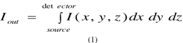
From the virtual source, projected points result from the integration of values encountered along the corresponding ray (see eq. 1).
Intrinsic 2D/3D registration based on a hybrid approach: Use in the radiosurgical imaging process. 63
ector source outI
x
y
z
dx
dy
dz
I
det)
,
,
(
(1)Where Iout the intensity after attenuation at the exit of the
volume, I(x,y,z) is the intensity at the position (x,y,z) such as the voxel grey level.
In some case it could be interesting to use a model closer to the actual photon beam attenuation as shown in eq. 2. The relation between the input and output intensities is therefore the integral of the linear attenuation coefficients along a ray.
e c tor sourc e dz dy dx z y x in outI
e
I
de t ) , , ( (2)Where Iin designates the intensity at entry of the volume, Iout
the intensity after attenuation at the exit of the volume, (x,y,z)
the attenuation coefficient at the position (x,y,z) in the volume. Theoretically (x,y,z) is different for each type of tissue crossed
by the beam, so in practise a constant value multiply by the grey level could be used to ease the computation.
The comparison between the DRRs and the original radiographs uses a similarity measure. Penney (8) provided a comparison of several similarity measures applied to 2D/3D intensity-based registration.
Feature-based approaches – Feature-based approaches (12,13) rely on the registration of geometric 2D and 3D primitives extracted from the images segmentation. The registration is then performed by an iterative process where the projected 3D structures are compared to the 2D structures through a least mean square distance for example. An illustration of feature-based approach is given Fig. 11.
Fig. 11 Illustration of the feature-based registration using skeleton, MRA/CT slices are segmented, centre lines are extracted and projected to the projection plan, the 2D skeleton obtained is compared to the centre lines extracted from X-ray angiography.
The hybrid approach The hybrid registration we have developed (7, 14, 15) is a compromise between these two techniques and is applied on non paired DSA images. A part of segmentation of the feature-based approach is retained for the MRA (Fig. 12 a), which is subjected to a semi-automatic processing to extract a part of the tree-structure. On the other hand, the DSA is not subjected to any processing other than the subtraction that is routinely used for removing the bone structures. This configuration is adapted from intensity-based registration.
The segmented MRA volume can be placed in the DSA space and virtually projected onto the imaging system sensor. For the projection, a fast solution fitting a photon attenuation model has been developed. This virtual X-ray projection allows a statistical dependency to be used, whatever the tomographic imaging method (Fig. 12 b).
Fig. 12 Hybrid registration, (a) reconstructed volume, (b) virtual DRR using fast projection of the vessel surface.
The part below describes point by point our methodology: Segmentation of MRA volume
F i rst, we gen er at e a M axi mu m o f I n t en si t y P ro j ect ion ( MIP ) as d es cr ib ed b elo w (F i g. 13 a ). A sp eci fi c ar t er y i s s el ect ed on th e MIP i mage ( F i g. 13 b ) u sin g a r egion gro wi n g al go ri th m s up er vised b y t h e ph ysi ci an .
Fig. 13 Maximum of Intensity Projection algorithm, (a) the maxima of grey levels among a ray are projected to a plan, which gives the image shown in (b).
The resulting segmented MIP image is used to detect the vascular structure through the entire MRA dataset, applying fuzzy set theory and data fusion. For each voxel a vessel membersh ip degree is computed , its value is between 0 and 1, 1 being the highest membership degree to a vessel. This degree (14) takes into account the Contrast to Noise Ratio, the neighborhood of each voxel. Fig. 14 shows an example of automatic detection performed by the algorithm where a threshold at 0.5 has been applied on the membership degrees. Once the contours of the vessel structure have been found, we use the method of 3D reconstruction proposed by Vial et al. (16).
Fig. 14 Resulting contour obtained with a threshold of 0.5 applied to the membership degree of the fuzzy image of the MRA during slices segmentation.
64
Projection
Although DRR and virtual X ray projection are quite similar, it must be pointed out that DRR is based on the projection of voxels (discrete), and therefore a complete tomographic volume, whereas our X-Ray projection is computed using a surface (continuous) defined by a series of vertices and polygons. This solution produces a reduced data set that provides a much faster projection while taking into account the attenuation through the matter.
Our projection algorithm relies on the projection of polygons (modeling the surface of the reconstructed volume) using the Z-Buffer algorithm to compute the thickness of matter crossed by the virtual photon beam. The grey level is then computed using the equation (2). The fig. 15 shows the principle in 2D.
Fig 15 Illustration of the projection algorithm used to simulate X-ray beam attenuation, this algorithm uses a “distance- buffer” and a “Z-buffer” to calculate the thickness of vessel which has been crossed.
At the end of the process, each pixel of the projection has a corresponding thickness of crossed matter stocked in the “distance buffer”, thus finally each pixel is set to:
dxtot
e GLMAX
pixel
(3)
Where GLMAX is the maximum of grey level (according to the DSA), dxtot is the thickness stocked in the distance buffer
and α represents the attenuation coefficient of the crossed matter (taken at 0.15)
The short computing time for each projection enables to achieve complete registration in about 2-3min per DSA view on a standard computer (Pentium IV, 2Ghz, 1Go of RAM). Similarity measure
The similarity measure calculated here to compare projection of the MRA volume and DSA is a basic quadratic distance between virtual projection and DSA, as shown on eq. 4.
2 1 1 , , '
I i J j j i j i P P Energy (4)Where, Pi,j and P’i,j are respectively the i and j coordinates
pixels of the original image I and the image I’ computed from projection. This measure has been used because it is very fast to compute and it is very sensitive to small translation which may exist between DSA and virtual X-ray projection.
Initialization
The initialization is driven interactively by the physician who roughly disposes the volume projection on the DSA, initializing in this way the 6 degrees of freedom.
Optimization
To optimize the volume position, we apply an algorithm developed by Salazar (17) and based on the Hybrid Monte Carlo
algorithm (HMC). This method, known as the Hybrid Simulated Annealing (HSA), has the property to modify simultaneously the parameters set using a simulated annealing scheme. Thus, HSA is almost as fast as a conjugate gradient but avoiding local minima. In its standard approach, the HMC introduces a set of auxiliary momenta variables p(p1, p2, …, pN) and a related
Hamiltonian function H(x,p), where x is the N parameters vector to optimize (here the six degree of freedom), given E the energy introduced by (4). 2 ) ( 2 1 ) , , ( ) , ( 2 1 2 2 1 p x E p x x x E p x H N i i N
(5)Vector p is a set of independent, Gaussian distributed, random variables of zero mean. New configurations are computed using the Hamilton's equation of motion, described by (4).
i
i p
x
, pi Fi (6)
The Hamilton's equation of motion are numerically integrated using a "leap-fog" scheme with a time step t. In this
way each new configuration, defined by x' and p', are computed by a set of relations (7). Where, Fi(x)=E(x)/xi is the force
acting on the variable xi.
( ) ( ')
, (1,..., ) 2 ' and , ) ( 2 ' 2 N i x F x F t p p x F t p t x xi i i i i i i i (7)As in the standard simulated annealing, the new configuration is accepted using the Metropolis test, with a probability described by (8). ) ( ) ( T H e H P (8)
The acceptance probability is computed from Hamiltonian variation HH(x',p')H(x,p), where T is the step temperature. When, stability is observed during a step, the temperature is cooled. The process is stopped when the global system is stable or when the temperature is equal to zero.
Our hybrid solution that is evaluated here for registration in radiosurgery has therefore proved to be very efficient in terms of accuracy and speed thanks to the fusion of conventional methods.
From 2D coordinates to 3D coordinates – Thanks to registration, the DSA views are paired using the MRA volume as a common reference. In such a configuration we can use the principle of epipolar geometry. Once projections are paired, the use of epipolar principle makes a point on one view corresponding to a point on specific line in the second view (Fig. 16).
Fig. 16 Illustration of epipolar geometry where p1 and p2 are the projection of a given target. Epipolar geometry enables to get the coordinate of the target when p1 and p2 are known and views paired.
Intrinsic 2D/3D registration based on a hybrid approach: Use in the radiosurgical imaging process.
65
In this way it is possible to navigate in the MRA and DSA projections (and vice-versa) by using the shared reference system defined by the volume (or the frame, in Leksell configuration).
RESULTS
The possible use of 2D/3D registration in the
irradiation planning in radiosurgery involves a stage of
evaluating the interchangeability of the anatomical
registration solution with the gold standard, which is
registration with the Leksell frame.
Therefore two stages were achieved: an evaluation
of the accuracy of the hybrid solution, on phantom and
clinical data and a ground truth validation. It should be
noted that, prior to this study, the robustness and
re-projection error (18) were already evaluated in a
previous work (14). The results obtained therefore
enabled us to initiate this study.
Evaluation of the accuracy on a phantom
A phantom of the vascular network (Fig. 17) was used
during the stage of evaluating the accuracy. Its known
geometry enabled us to determine the accuracy of the
stereoscopic pairing of DSA views. MRA and DSA of
the phantom were acquired. We obtained coronal, sagittal
and axial image sets from MRA and four DSA
projections. The volume reconstructed from MRI sets
was registered with each of the four projections. The
distances between the different "branches" of the vascular
network were measured each couple of projections and
compared to the known physical distances.
Fig. 17 Vascular phantom with specific measures required for the evaluation (a) and its vascular shape reconstruction from MRI (b).
The measurement of the distances used the
principles of epipolar geometry (Fig. 16). A point
was chosen on a first DSA view and its
homologue on the other view. The intersection of
the two corresponding epipolar straight lines
gave us the coordinates of the 3D point in the
DSA space. The same operation repeated for
each point (Fig. 18) of a segment finally drives
us to determine 3D distances.
Fig. 18 Measurement on the phantom using interactive navigation, physician can select a point on the lateral DSA view and its homologue on the frontal view DSA (a) the algorithm computes the corresponding point in the MRA space (b), the physician can also select a point on MRI slices, the corresponding point is thus shows on the DSA view.
During the evaluation stage the extremity of the
segment appeared with much more contrast than the
rest of the phantom, which assumes to have a good
robustness and reproducibility of measurement.
66
This method of validation by epipolar geometry
is particularly interesting since it tests both the
validity of the registration, which is in our case the
only means of pairing DSA projections, and it
provides
the
quantitative
accuracy
of
the
registration. The 3D distance errors obtained are
given in Table 3.
Table 3 Results of measurements on the phantom where 3D distances were measured using the interactive navigation tools (fig. 18).
Root Mean Square Error 0.7mm Standard Deviation error 0.6mm Maximum error 0.9mm
The error presented is based on the difference between the real distance and the measured distance.
Evaluation of the accuracy under clinical conditions
For the patients study, a good way to estimate the
accuracy is to use non-invasive fiducial marker.
Unfortunately, MRA and DSA could not be acquired
on the same day. Using markers in both modalities
cannot be reproducible because of the lack of
accuracy when placing markers for MRA and then
for DSA. In this configuration it is impossible to
measure reprojection error or 3D distance error.
Actually, in our methodology the DSA views are not
initially paired, only the registration with a single
volume can pair the views. Thus we have chosen to
use only markers with DSA and to estimate the
epipolar error which is the deviation between two
epipolar straight lines. Since epipolar error gives the
accuracy of pairing projections, it constitutes an
indirect but absolute measure of registration
accuracy.
Images were acquired using a standard clinical
protocol defined by physician and used for aneurysm
treatment. In accordance with the clinical protocol,
three non invasive markers were placed for 4
patients during their DSA exams. No particular
orientation constraint nor additional image was
required. Each marker is selected on a view and its
homologue on the other, and the error is computed.
Using small markers assumes to have a good
robustness and reproducibility of measurement. The
epipolar errors obtained during the measurement on
patients are given in Table 4.
Table 4 Results of measurements obtained on clinical data, 3 markers are selected on the DSA views, the error presented is the epipolar error.
Maximum error 0.8mm Standard deviation error 0.3mm
"Ground truth" validation
In this study, the term "ground truth" validation
means the comparison of our method with the real
radiosurgery conditions practised using the Leksell
frame. For the validation, as the MRI-Leksell
transformation is known, we have to compare the
coordinates of the same points obtained by Leksell
localization and the 2D/3D registration.
For this protocol, 3 patients treated by
radiosurgery were given DSA and MRA localization
exams. These exams were processed firstly by
standard localization using the Leksell reference
system and secondly using 2D/3D registration. It
was therefore possible to validate the registration by
means of an objective comparison of the two
techniques, the Leksell localization being the
so-called ground truth.
The validation (Fig. 19) was performed using the
DSA.
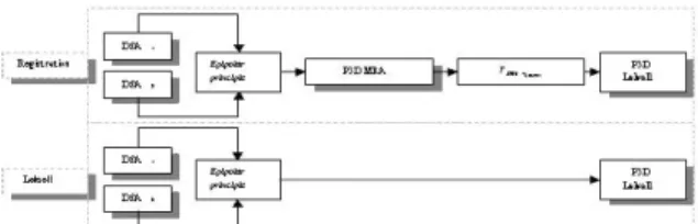
Fig. 19 Detail of transformations needed to obtain Leksell coordinates from the DSA space depending on initial conditions: intrinsic registration or Leksell registration.
On each of the views, 4 points, designating in
each case the same 3D element (elements of the
Leksell frame to avoid bias during the measures),
was selected. In the localization configuration using
the stereotactic frame, the 3D coordinates of the
point can be deduced directly within the Leksell
space. In the second case, where the localization is
deduced from registration, the 3D coordinates of the
point are calculated in the MRA reference system
from the same series of DSA coordinates.
To compare the measurements, the points
obtained in the MRA space have to be converted to
the Leksell reference system by means of the MRA
Leksell transformation. In this way we obtain two
series of coordinates in the Leksell space for the
same 3D point. The deviation measured illustrates
the error between the two localization methods. The
results are given in Tables 5 and 6.
Table 5 Results obtained for measurements achieved with and without Leksell localization.
X Y Z X Y Z 68.13 82.31 115.36 69.4 82.8 114.72 75.38 83.26 115.37 77.0 83.12 115.05 63.54 98.88 123.77 64.5 98.0 123.0 56.6 73.66 115.06 55.5 71.5 114.0 131.1 106.3 69.3 130.14 107.62 70.74 125.8 115.1 90.6 125.12 115.13 91.4 126.0 118.9 83.7 125.0 118.7 85.0 120.5 110.9 85.5 119.7 111.3 86.2 130.1 91.1 95.1 129.99 93.0 95.05 139.4 90.3 85.4 139.1 93.0 86.2 124.7 89.2 107.1 124.85 91.2 106.86 142.6 108.1 97.0 142.42 110.0 97.5 Lek3
Coordinates in leksell space from registration
Lek1
Lek2
Coordinates in leksell space from frame Patient
Average Error
1.84
Maximum error
2.83
0.54
Standard deviation
The error presented is the distance between the 3D coordinate given by the Leksell registration and the 3D coordinates given by the hybrid registration.
Intrinsic 2D/3D registration based on a hybrid approach: Use in the radiosurgical imaging process.
67
Table 6 Average and standard deviation of error on each component of the 3D coordinates.
Error on: X Y Z Average 0.76 1.17 0.71 Standard
deviation 0.48 0.93 0.41 The error is the absolute difference between a component given by the Leksell registration and a component given by the hybrid registration (e.g. X or Y or Z).
DISCUSSION
The intensity-based method has been found to be
very precise but relatively time consuming and
suitable for the registration of images produced by
the same physical phenomenon (e.g. X-rays for CT
and DSA) because of their statistical dependence.
For example, Murphy (10) had proposed an
intensity-based approach to match CT and DSA for
a similar application in radiosurgery. His approach
has been proved to be precise. Unfortunately, it
cannot be applied in our case for two reasons:
Murphy’s method required paired projections and
we work on MRA images.
Feature-based methods are very fast but have a
significant
imprecision
for
radiosurgery.
Furthermore, the many intermediate steps (e.g.
segmentation) limit their use.
Finally, in most of cases proposed in the
literature for intensity or feature-based method,
registration relies on paired DSA images, which is
not the case of the hybrid approach.
During the evaluation stage and after registration,
the measurements of the distances on the phantom
gave perfectly acceptable results, since the
maximum distance error observed was always less
than one millimetre.
The accuracy evaluated on clinical data
confirmed that the epipolar constraints were verified
after registration. In practice, the epipolar straight
lines were only a few tenths of a millimetre apart
(max. error 0.8mm, SD 0.3). This weak error
confirms the good accuracy of the registration when
using injected MRA.
For the validation stage during the radiosurgery
protocol, the measurements showed an acceptable
error on the X and Z axes, but revealed a significant
error on the Y axis. This observation led us to
reconsider the quality of the TOF images used for
the validation because a such a phenomenon does
not appear when using gadolinium.
It appears that the TOF images required very high
spatial coding gradients that are potentially
non-linear, and could be the source of major distortions in
the XY plane (acquisition plane for axial images).
We were able to confirm this hypothesis by
taking measurements of the distances on the Leksell
frame on axial images (Fig. 20) taken with a TOF
sequence (a) and with a standard sequence (b)
resulting in much smaller gradients. It was clearly
evident that the TOF images were subjected to a
deformation in the Y axis. This deformation led to
an error during the reconstruction of the registration
volume, which made determination of localization
matrices imprecise. Extra-fast sequences do not
therefore seem to be very suitable for registration,
unless a method can be developed for correcting the
distortions caused, which is not currently the case.
Fig. 20 Illustration of the distortions of TOF images (a) compare to standard acquisition parameters (b), the measures are taken on the Leksell frame which is supposed to be rigid.
CONCLUSION
In this study we have described the validation
steps
required
for
applying
registration
of
multimodality images in radiosurgery. These
registration techniques will eventually allow us to
replace the DSA localization exam by the standard
diagnostic exam.
The protocol presented here is based on an
evaluation of accuracy and on a validation under
clinical
conditions,
where
validation
means
comparing intrinsic registration with a gold standard
technique.
The validation procedure that we have applied
has revealed a lack of accuracy (maximum error
2.83mm, SD 0.54), making the method unsuitable
for radiosurgery treatment. However, a study of the
errors observed has highlighted problems associated
with TOF images. Their intrinsic distortions in the
XY (axial) plane make it difficult to perform an
accurate registration. But the routine use of
MRA/DSA registration could still be envisaged.
MRA with the injection of a contrast agent seems to
be more suitable for this application, as shown by
the accuracy study.
The studies conducted on the phantom and on
patients are however fairly conclusive and lead us to
think that routine use is very probable in the future.
The degree of accuracy obtained is equivalent to the
accuracy when using external markers. It therefore
seems possible to quantify an AVM by using
68
frameless and non-paired DSA images, since MRA
acquisition is increasingly being requested by
physicians. For the reasons exposed in the
introduction, the substitution of the localization DSA
by the diagnostic exam would greatly improve the
treatment protocol. If the method is to be used
routinely in clinical practice, further studies are
needed on the 3D mapping of epipolar errors, which
would constitute a model of registration error and
which would allow us to observe the spatial limits of
registration. A complete clinical study will also be
needed. The clinical test protocols, defined by the
various specialists involved in Gamma Knife
treatment (Neurosurgeons, Neuroradiologists and
Radiotherapists) will require the combined use of
localization and diagnostic images. The localization
images are used to plan the operation under standard
conditions, whereas the diagnostic images are used
in parallel. The dosimetries produced for each type
of image could therefore be compared. The
measurements shown through the form of Bland and
Altman (19) graphs should be used to study the
consistency of the dosimetry with and without
localization images. It would demonstrate the
interchangeability between the Gold Standard and
the use of our frameless DSA registration approach.
In that manner, our method could be applied in daily
practice to improve effectiveness and simplicity of
the surgical procedure.
REFERENCES
1. Antoine Maintz, J.B.; Viergever, Max A. “A survey of medical image registration: Medical Image Analysis”, Vol.
2, n° 1. 1998, pp: 1-36.
2. Wan Rui, Li Minglu, “An Overview of Medical Image Registration”, Fifth International Conference on Computational Intelligence and Multimedia Applications (ICCIMA’03), 2003.
3. Constantinos, S.P.; Pattichis, M.S.; Micheli-Tzanakou, E. "Medical imaging fusion applications: An overview”, Signals, Systems and Computers, Conference Record of the
Thirty-Fifth Asilomar Conference on, Vol. 2. 2001, pp:
1263-1267.
4. Gibon, D., Rousseau, J., Castelain, B., Vasseur, C., Marchandise, X., "Treatment planning optimization by conjugate gradients and simulated annealing methods in stereotactic radiosurgery", International Journal of Radiation
Oncology Biology Physics, Vol. 33. 1995, pp: 201-210.
5. Kulik, C., Caudrelier, J.M., Vermandel, M., Castelain, B., Maouche, S., Rousseau, J., "Conformal radiotherapy optimization with micro-multileaf collimators, comparison with radiosurgery techniques", International Journal of
Radiation Oncology Biology Physics, Vol. 53, n° 4. 2002,
pp: 1038-1050.
6. Gibon, D., Coste, E., Vial, S., Vasseur, C., and Rousseau, J.: "Stereotactic localization in medical imaging. A technical and methodological review", J. Rad. Surger., vol.
2, n° 3. 1999, pp: 167-180.
7. Vermandel, M., Betrouni, N., Pasquier, D., Gauvrit, J.Y., Vasseur, C., Rousseau, J., " A 2D/3D matching based on a hybrid approach: improvement to the imaging flow for AVM radiosurgery", 27th Annual International Conference of the IEEE Engineering in Medicine and Biology Society. 2005, pp: 2148-2150.
8. Penney, G.P., Weese, J., Little, J.A., Desmedt, P., Hill, D.L., Hawkes, D.J., "A comparison of similarity measures for use in 2D-3D medical image registration", IEEE TMI
Vol. 17, n°4. 1998, pp: 586-595.
9. Brown, L. M. G., Boult, T. E., "Registration of Planar Film Radiographs with Computed Tomography", MMBIA. 1996,
pp: 42-51.
10. Murphy, M.J., “An automatic six-degree-of-freedom image registration algorithm for image-guided frameless stereotaxic radiosurgery”, Medical Physics, Vol. 24, n° 6. 1997, pp: 857-866.
11. Weese, J., Buzug, T.M., Lorenz, C., Fassnacht, C., "An approach to 2D/3D registration of a vertebra in 2D X-Ray fluoroscopies with 3D CT images", CVRMed/MRCAS'97,
LNCS, Vol. 1205. 1997, pp: 119-128.
12. Hamadeh, A., Cinquin, P. "Kinematic study of lumbar sine using functional radiographs and 3D/2D registration",
CVRMed/MRCAS'97, LNCS, Vol. 1205. 1997, pp:
109-118,.
13. Feldmar, J., Malandain, G., Ayache, N., Fernàndez-Vidal, S., Maurincomme, E., Trousset, Y. "Matching 3D MR Angiography data and 2D X-Ray Angiograms",
CVRMed/MRCAS'97, LNCS, Vol. 1205. 1997, pp: 129-138.
14. Vermandel, M., Betrouni, N., Palos, G., Gauvrit, JY., Vasseur, C., Rousseau, J., "Registration, matching and data fusion in 2D/3D Medical Imaging: application to DSA and
MRA", MICCAI'03, LNCS, Vol 2878. 2003, pp: 778-785.
15. Vermandel, M., Dewalle, A.S., Palos, G., Vasseur, C., Rousseau, J. "Recalage et mise en correspondance d'images tomographiques et de projection. Cas de l'Angiographie par Résonance Magnétique (ARM) et de l'Angiographie par Rayons X (ARX)", Traitement du Signal et de Image, Vol.
20, n°2. 2003, pp: 165-181.
16. Vial, S., Gibon, D., Vasseur, C., Rousseau, J., “Volume delineation by fusion of fuzzy set obtained from multiplanar tomographic images”, IEEE TMI, Vol. 20,
n°12. 2001, pp: 1362-1372.
17. Salazar, R., Toral, R., “Simulated Annealing using Hybrid Monte Carlo”, Journal of Statistical Physics, vol. 89, n°
5/6. 1997, pp: 1047-1053.
18. McLaughlin RA, Hipwell J, Hawkes DJ, Noble JA, Byrne JV, Cox TC. A comparison of a similarity-based and a feature-based 2-D-3-D registration method for neurointerventional use. IEEE Trans Med Imaging. Vol. 24,
n°8. 2005, pp: 1058-66.
19. Bland, J.M., Altman, D.G., "Statistical methods for assessing agreement between two methods of clinical measurement", Lancet. 1986, pp: 307-310.