HAL Id: hal-01314981
https://hal.archives-ouvertes.fr/hal-01314981
Submitted on 12 May 2016
HAL is a multi-disciplinary open access
archive for the deposit and dissemination of
sci-entific research documents, whether they are
pub-lished or not. The documents may come from
teaching and research institutions in France or
abroad, or from public or private research centers.
L’archive ouverte pluridisciplinaire HAL, est
destinée au dépôt et à la diffusion de documents
scientifiques de niveau recherche, publiés ou non,
émanant des établissements d’enseignement et de
recherche français ou étrangers, des laboratoires
publics ou privés.
Miniature and Wide-Band ILA Antenna with
Non-Foster Matching
Abdullah Haskou, Dominique Lemur, Sylvain Collardey, Ala Sharaiha
To cite this version:
Abdullah Haskou, Dominique Lemur, Sylvain Collardey, Ala Sharaiha. Miniature and Wide-Band
ILA Antenna with Non-Foster Matching. 10th European Conference on Antennas and Propagation
(EuCAP’2016), Apr 2016, Davos, Switzerland. �hal-01314981�
Miniature and Wide-Band ILA Antenna with
Non-Foster Matching
Abdullah Haskou, Dominique Lemur, Sylvain Collardey, and Ala Sharaiha
IETR UMR CNRS 6164- Université de Rennes 1, Rennes, France
abdullah.haskou@univ-rennes1.fr, dominique.lemur@univ-rennes1.fr, sylvain.collardey@univ-rennes1.fr,
ala.sharaiha@univ-rennes1.fr
Abstract—In this paper, we present a miniature, wide-band, Inverted L Antenna (ILA) with non-Foster matching. The antenna size is 9.5× 19.5 mm2 and it is integrated on a Printed Circuit Board (PCB) of 100× 60 mm2. The antenna covers the whole frequency band of (0.76− 2.17) GHz and the circuit is stable throughout this band.
Keywords—Electrically small antenna, miniaturization, non-Foster
I. INTRODUCTION
Antenna miniaturization is the key for a compact wireless technology. The main drawbacks of Electrically Small Anten-nas (ESAs) are their low efficiencies and narrow bandwidths even when a passive matching circuit is used. The maximum achievable bandwidth with passive matching is limited by the theoretical limits of Bode-Fano [1] and Chu-Harrington [2], [3]. A possible solution is the use of non-Foster matching that surpass these limits [4] and enhance miniature antenna perfor-mance in reception [5]. A.J. Bahr showed that using an active coupling network with a receiving antenna (a short monopole) can significantly improve its Noise Figure (NF) [6]. Sussman-Fort experimentally showed that using a negative capacitor for matching a 152.4-mm monopole for (20− 110) MHz frequency band presents a significant improvement in the Signal to Noise Ratio (SNR) compared to the same antenna without matching [7]. Koulouridis and Volakis demonstrated that using a non-Foster circuit to match a 152.4-mm loop can highly increase its bandwidth and decrease its resonance frequency [8]. G. Mishra et al presented a Bowtie antenna covering (0.6− 1.1) GHz frequency band using a non-Foster circuit [9]. The design of non-Foster circuits becomes more challenging when targeting at higher frequencies (due to the active components non-Linearity) and when targeting high impedance values (due to the parasitic elements).
In this paper, we present a broadband miniature Inverted L Antenna (ILA) with a non-Foster matching. In particular, we focus our attention on exploiting the parasitic capacitance of the transistors in order to match this antenna requiring a high reactance value. By using the proposed non-Foster circuit, we demonstrate three times improvement in the antenna−10 dB bandwidth compared to the passive antenna. The realistic implementation and stability issues are discussed throughout the paper.
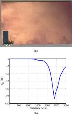
II. ANTENNASTRUCTURE ANDNON-FOSTERCIRCUIT The proposed antenna is an ILA of 9.5 × 19.5 mm2 integrated on a Printed Circuit Board (PCB) 100× 60 mm2
as shown in Fig. 1(a). This antenna, printed on a 0.8mm-thick Rogers Duroid 5880 substrate, has a measured resonance frequency of 2.39 GHz (1(b)). (a) 0 500 1000 1500 2000 2500 3000 −30 −25 −20 −15 −10 −5 0 Frequency [MHz] S11 [dB] (b)
Fig. 1. Passive ILA. (a) The realized prototype, (b) measured input reflection coefficient magnitude in dB.
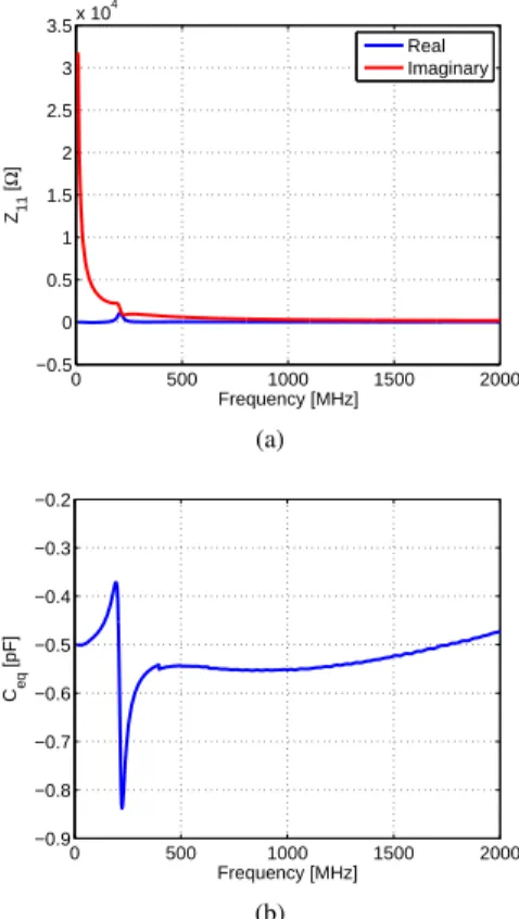
To eliminate the reactance of the antenna at 910 M Hz, a negative capacitor of 0.7 pF is required. We optimized a Linvill floating type [10] Negative Impedance Convertor (NIC) circuit to realize this capacitance as shown in Fig. 2. The active components in the circuit are BFR93A transistors [11]. The circuit is supplied by 4 VDC, it consumes a current of 24mA or
equivalently a DC power of 96mW . The measured reactance of this circuit is shown in Fig. 3(a). As it can be noticed, the circuit reactance decreases with frequency which means that the circuit has a non-Foster behavior (negative capacitance). The value of the equivalent capacitance is given in Fig. 3(b).
Port1
Port2
(a) (b)
Fig. 2. Proposed NIC circuit. (a) General schematic of Linvill floating circuit and (b) photograph of the prototype.
0 500 1000 1500 2000 −0.5 0 0.5 1 1.5 2 2.5 3 3.5x 10 4 Frequency [MHz] Z11 [ Ω ] Real Imaginary (a) 0 500 1000 1500 2000 −0.9 −0.8 −0.7 −0.6 −0.5 −0.4 −0.3 −0.2 Frequency [MHz] Ceq [pF] (b)
Fig. 3. Measured parameters of NIC circuit. (a) Input reactance and (b) equivalent capacitance.
III. ACTIVEANTENNAPERFORMANCE
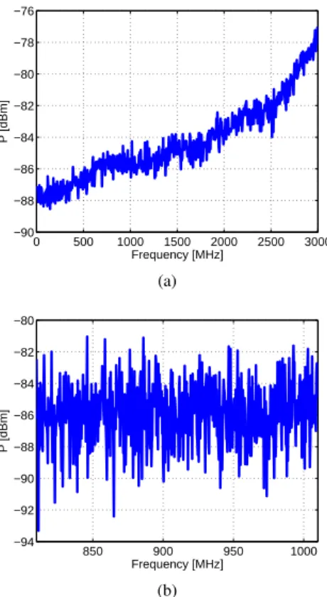
A prototype of the antenna with the non-Foster circuit was realized and measured. Fig. 4 shows a photograph of the active antenna with the NIC circuit on the bottom side. Fig. 5 shows the antenna measured input reflection coefficient magnitude in dB. It can be noticed that antenna has an impedance bandwidth of 100 % (matched throughout (0.76− 2.17) GHz frequency band). The antenna was also tested for transistors non-linearity effect by increasing the input power level from −35 dB to 10 dBm. The measurement results given in Fig. 6 shows that the antenna is well suited for RF power levels less than 5 dBm. Finally, the antenna stability has been underlined using a spectrum analyzer (RIGOL DSA1030 [12]) with a Power Spectral Density (PSD) of −134 dBm/Hz. Fig.7 shows the noise floor of the spectrum analyzer. It can be noticed that no visible additive noise affect the bandwidth of interest. To investigate the added noise by the non-Foster circuit, we compare the output of the spectrum analyzer when connected
to the non-Foster antenna and when connected to a 50Ω load. The measurement conditions are the same as before, however, the results are averaged on 10 cycles for fair comparison. The obtained results given in Fig. 8 shows that the added noise by the non-Foster circuit is negligible.
(a)
(b)
Fig. 4. A photograph of the fabricated active antenna. (a) Top view and (b) bottom view. 0 500 1000 1500 2000 2500 3000 −16 −14 −12 −10 −8 −6 −4 −2 0 Frequency [MHz] S11 [dB]
Fig. 5. The measured input reflection coefficient magnitude in dB of the active antenna. 0 500 1000 1500 2000 2500 3000 −16 −14 −12 −10 −8 −6 −4 −2 0 Frequency [MHz] S11 [dB] Pin=−35dBm Pin=−25dBm P in=−15dBm P in=−5dBm P in=+5dBm P in=+10dBm
Fig. 6. The measured input reflection coefficient magnitude in dB of the active antenna for different input power levels.
0 500 1000 1500 2000 2500 3000 −90 −88 −86 −84 −82 −80 −78 −76 Frequency [MHz] P [dBm] (a) 850 900 950 1000 −94 −92 −90 −88 −86 −84 −82 −80 Frequency [MHz] P [dBm] (b)
Fig. 7. The noise floor level of the spectrum analyzer terminated at the input with the non-Foster matched antenna. (a) On (0.01−3) GHz frequency band and (b) on (0.81− 1.01) GHz frequency band.
0 500 1000 1500 2000 2500 3000 −90 −88 −86 −84 −82 −80 −78 −76 Frequency [MHz] P [dBm] Antenna 50Ω load
Fig. 8. A comparison between the noise floor levels of the spectrum analyzer terminated at the input with a matched load and non-Foster matched antenna.
IV. CONCLUSION
In this paper, we presented a miniature broadband ILA. The passive antenna resonant at 2.39 GHz was matched in the (0.76−2.17) GHz band using a Linvill floating-type non-Foster circuit. The measurement results show that the antenna is stable and demonstrates a good behavior across the band of interest.
ACKNOWLEDGMENT
This work was done with the funding of the French National Research Agency as part of the project "SENSAS".
REFERENCES
[1] R. M. Fano, "Theoretical Limitations on the Broadband Matching of
Arbitrary Impedances", J. Franklin Institution, vol. 249, pp. 57-83 and
139-155, January and February 1950.
[2] L. .J. Chu, "Physical Limitations of OmniDirectional Antennas", Journal of Applied Physics, vol. 19, no. 12, pp. 1163-1175, 1948.
[3] R. F. Harrington, "On the Gain and Beamwidth of Directional Antennas", IRE Transactions on Antennas and Propagation, pp. 219-225, July 1958. [4] M. Hirvonen, A. Hujanen, J. Holmberg, and J.C.-E. Sten, "Bandwidth
Limitations of Dipoles Matched with Non-Foster Impedances", The
Second European Conference on Antennas and Propagation (EuCAP 2007), pp. 1,5, 11-16 November 2007.
[5] J. T. Aberle, "Two-Port Representation of an Antenna with Application
to Non-Foster Matching Networks", IEEE Transactions on Antennas and
Propagation, vol. 56, no. 5, pp. 1218,1222, May 2008.
[6] A. Bahr, "On The Use of Active Coupling Networks with Electrically
Small Receiving Antennas", IEEE Transactions on Antennas and
Propa-gation, vol. 25, no. 6, pp. 841,845, November 1977.
[7] S. E. Sussman-Fort, "Matching Network Design Using NonFoster
Impedances", International Journal of RF and Microwave
Comput-erAided Engineering, vol. 16, no. 2, p.p. 135-142, 2006.
[8] S. Koulouridis, and J. L. Volakis, "Non-Foster Circuits for Small
Broad-band Antennas", IEEE Antennas and Propagation Society International
Symposium (APSURSI 2009), pp.1,4, 1-5 June 2009.
[9] G. Mishra, S. K. Sharma, and G. Rebeiz, "Non-Foster Matching of
Eclectically Small Bowtie Antenna Covering 600MHz to 1100MHz",
2015 IEEE Symposium on Antennas and Propagation (APS 2015), 19-25 July, 2015.
[10] J. G. Linvill, "Transistor Negative-Impedance Converters", Proceedings of the IRE, vol. 41, no. 6, pp. 725-729, June 1953.
[11] [Online]. Available: http://pdf1.alldatasheet.com/datasheet-pdf/view/ 16347/PHILIPS/BFR93A.html
[12] [Online]. Available: http://beyondmeasure.rigoltech.com/acton/ attachment/1579/f-0025/0/-/-/-/-/file.pdf