HAL Id: hal-01511048
https://hal.archives-ouvertes.fr/hal-01511048
Submitted on 20 Apr 2017
HAL is a multi-disciplinary open access
archive for the deposit and dissemination of
sci-entific research documents, whether they are
pub-lished or not. The documents may come from
teaching and research institutions in France or
abroad, or from public or private research centers.
L’archive ouverte pluridisciplinaire HAL, est
destinée au dépôt et à la diffusion de documents
scientifiques de niveau recherche, publiés ou non,
émanant des établissements d’enseignement et de
recherche français ou étrangers, des laboratoires
publics ou privés.
Decoupling Approach of Superdirective Antenna Arrays
Abdullah Haskou, Ala Sharaiha, Sylvain Collardey
To cite this version:
Abdullah Haskou, Ala Sharaiha, Sylvain Collardey. Decoupling Approach of Superdirective Antenna
Arrays. The 11th European Conference on Antennas and Propagation, Mar 2017, Paris, France.
�hal-01511048�
Decoupling Approach of Superdirective Antenna
Arrays
Abdullah Haskou, Ala Sharaiha, and Sylvain Collardey
IETR UMR CNRS 6164- Université de Rennes 1, Rennes, France
[email protected], [email protected], [email protected]
Abstract—The inter-element distance in superdirective arrays
is usually very small and hence the mutual coupling is consid-erably high. Consequently, these arrays present relatively low efficiencies. In this paper, we propose using decoupling techniques for reducing the mutual coupling, and hence increasing the efficiency, in this kind of arrays. The concept is proven by full wave simulations of two different Electrically Small Antenna (ESA)-based two-element arrays with an inter-element distance of 0.1λ. In the first array with a ka = 0.56, the original (before decoupling) radiation efficiency of 7% is increased to 13.4% and the realized gain is increased from−6.4dBi to −2.6dBi. In the second array with a ka = 1.18, the original radiation efficiency of 52.1% is increased to 63.7% and the realized gain is increased from 3dBi to 3.9dBi.
Index Terms—Superdirectivity, decoupling, directivity,
radia-tion efficiency
I. INTRODUCTION
Electrically Small Antennas (ESAs) are very important for compact hand-held technologies. However, these antennas are known for their quasi-isotropic radiation patterns. To keep the size advantage of ESAs while significantly increasing their di-rectivity, one can integrate them in superdirective arrays where the inter-element distance is usually a fraction of the wave-length. The available literature is rich of successful realizations of ESA-based superdirective arrays [1]-[7]. However, due to the small inter-element distance, these arrays suffer from high mutual coupling and as a consequence small efficiencies. Re-cently, multiple decoupling techniques were presented [9]-[12]. In [9], an eigenmode feed network was used to decouple a two-element array yielding a mutual coupling reduction of 15dB. In [10], the authors proposed using a parasitic loaded scatter to decouple a two-element monopole array. A simulated coupling reduction of 31dB was achieved. In [11], a decoupling circuit was used to decouple a two-element patch array achieving a mutual coupling decrement of 5dB. The decoupling can also be done by using bandstop filters between the array elements as in [12] where interdigital capacitor loaded slots were used to decouple a two-element patch array revealing a coupling mitigation of 15dB. In the open literature decoupling is mainly used to mitigate the correlation coefficient and improve the diversity gain in MIMO arrays. In this paper, we propose using the decoupling techniques in superdirective arrays to increase their efficiency. This proposition is validated by the design of two parasitic ESA-based two-element arrays with an inter-element distance of 0.1λ. The simulation results show that the proposed method significantly increases the array efficiency.
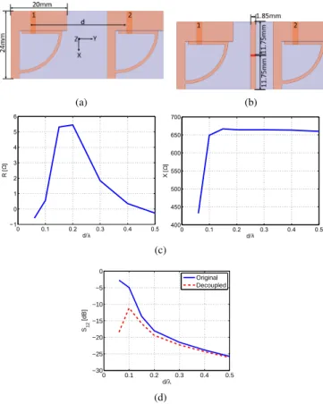
II. GEOMETRY ANDSIMULATIONRESULTS Let us take the example of a two-element ESA based array shown in Fig. 1(a). This antenna is printed on a 0.76mm-thick Rogers RO4003 substrate (ϵr= 3.55, tan(δ = 0.0027).
The array simulated ([8]) mutual coupling as a function of the inter-element distance (d) is given in Fig. 1(a). These results show that the coupling between the two elements is very important for small distances, and as the distance increases the coupling decreases. However, the maximum directivity is attained when the distance approaches zero. Hence, decoupling the two elements can be very interesting upto around 0.15λ. The method presented in [10] was used to decouple the array two elements. However, to keep the original inter-element distance for small distances, a short printed monopole, and not and an identical antenna, was used for the decoupling as shown in Fig. 1(b). To decouple the two elements, the dipole should be loaded with the loads given in Fig. 1(c). As it can be noticed, for small distances a small negative resistance is required. Starting from 0.07λ, the value of the required resistance become positive and it increases with the distance till around 0.2λ where it starts decreasing again. As for the required reactance, it can be noticed that it also increases with the distance till around 0.15λ where it stabilizes. To simplify the antenna realization, the required negative resistance is neglected. Moreover, to reduce the losses in the dipole, the required positive resistance is also neglected and the dipole is only loaded with an inductor. Standard inductor values are considered in simulation. As it can be seen from Fig. 1(d), for small distances the coupling level can be significantly reduced. However, as the distance increases, and due to neglecting an important resistive load, the coupling decrement becomes less important. In [7], a design approach for parasitic-loaded superdirective arrays was presented. The method was used to design two two-element ESA-based arrays with an inter-element distance of 0.1λ. In this section, we will investigate the effect of the decoupling on different antenna parameters.
A. Small Antenna Array
The first array presented in [7] is the same as the one shown in in Fig. 1(a) with d = 34mm = 0.1λ. This array was designed for 905M Hz, had dimensions of 54× 24mm2, or equivalently had a ka = 0.56. To maximize the directivity in the end-fire direction (θ = 90o, ϕ = 270o), the antenna two elements current excitation coefficients were respectively 1, 1.32ej150.4o
. This fully driven array, presented a simulated directivity of 7.1dBi. Then, to transform the array to a parasitic one, the second element was loaded with a capacitor of 5.1pF . The parasitic array presented a directivity of 7dBi, a
(a) (b) 0 0.1 0.2 0.3 0.4 0.5 1 0 1 2 3 4 5 6 d/ R [ ] 0 0.1 0.2 0.3 0.4 0.5 400 450 500 550 600 650 700 d/ X [ ] (c) 0 0.1 0.2 0.3 0.4 0.5 −30 −25 −20 −15 −10 −5 0 d/λ S12 [dB] Original Decoupled (d)
Fig. 1. Small antenna array geometry. (a) Reference array, (b) with decoupling (c) required load for decoupling the two elements and (d) simulated mutual coupling S12in dB.
radiation efficiency of 7.1% and a realized gain of −6.4dBi. The aforementioned technique was used to decouple the two elements. The monople is loaded at the input with an inductor of 115nH. This loading shifts the first element resonance to 898M Hz (this is the element to be excited when transforming the array to a parasitic one). This resonance can be easily tweaked to its original value however this is not the scope of this paper; instead the array is directly optimized at the new resonance frequency. As it can be seen from Fig. 2, the antenna mutual coupling S12, compared at the corresponding
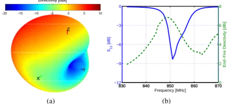
resonances, is reduced from−4.8dB to −11dB. The antenna excitation coefficients for achieving superdirectivity in this case are 1, 2.25ej122.6o. The fully driven array achieves a directivity of 6.5dBi. Then, to transform the array to a parasitic one, the second element should be loaded with 41Ω//1.8pF . This antenna presents a directivity of 6.5dBi (Fig. 3(a)), a radiation efficiency of 13.4% and a realized gain of−2.6dBi. The antenna input reflection coefficient magnitude in dB and end-fire directivity given in Fig. 3(b) shows that, despite the decoupling, the array can be optimized to achieve the maxi-mum directivity at the resonance frequency. Table I compares the performance of the parasitic array in the two cases.
TABLE I. ASUMMARY OF THE SIMULATED RESULTS OF THE
PARASITIC SMALL ANTENNA ARRAY.
Antenna D[dBi] ηrad[%] G[dBi] Grealized[dBi]
Reference 7 7 -4.5 -6.4 Decoupled 6.5 13.4 -2.3 -2.6 880 890 900 910 920 −50 −40 −30 −20 −10 0 Frequency [MHz] Sij [dB] S11 S12 S22
Fig. 2. Small antenna array simulated S parameters. Reference (continuous) and with decoupling (dashed).
(a) 880 890 900 910 920 −12 −9 −6 −3 0 S11 [dB] Frequency [MHz] 880 890 900 910 920 0 2 4 6 8
End−Fire Directivity [dBi]
(b)
Fig. 3. Parasitic small antenna array simulated parameters. (a) 3D total directivity radiation pattern at the resonance and (b) input reflection coefficient magnitude in dB and end-fire directivity as a function of the frequency.
B. Small Antenna Array on a PCB
The second array in [7], shown in Fig. 4(a), designed for 866M Hz was mounted on a PCB of 110× 70mm2. To
maximize the directivity in the end-fire direction, the antenna two elements current excitation coefficients were respectively 1, 0.55ej−101.6o. The fully driven array, presented a simulated directivity of 7.2dBi. To transform the array to a parasitic one, the first element was loaded with an inductor of 4.35nH. At the resonance, this array presented a simulated directivity of 6.6dBi, a radiation efficiency of 52.1% and a realized gain of 3dBi. Using the same decoupling element as in the previous case shows that a complex load is required (1.83Ω in series with 124.5nH). Replacing these values with the standard component values, i.e. 1.8Ω and 120nH, leads to a coupling level of −6dB. To avoid the complex load and enhance the decoupling, the decoupling dipole was extended as shown in Fig. 4(b). In this case the dipole is only loaded with 13nH. This loading shifts the first element resonance to 851M Hz. In this case, as it can be seen from Fig. 5, the mutual coupling is reduced from−5.7dB to −15.7dB. The array re-optimized excitation coefficients are 1, 1.24ej−95o. The fully driven array
presents a directivity of 6.5dBi. To transform the array to a parasitic one, the second element is loaded with 24nH. The antenna presents a directivity of 6.6dBi (Fig. 6(a)), a radiation efficiency of 63.7% and a realized gain of 3.9dBi. The antenna input reflection coefficient magnitude in dB and end-fire directivity is given in Fig. 6(b). Table II summarizes the simulation results in both cases.
(a) (b)
Fig. 4. Small antenna array on a PCB geometry. (a) Reference array and (b) with decoupling. 830 840 850 860 870 −50 −40 −30 −20 −10 0 Frequency [MHz] Sij [dB] S11 S12 S22
Fig. 5. Small antenna array on a PCB simulated S parameters. Reference (continuous) and with decoupling (dashed).
III. CONCLUSION
In this paper, we proposed decoupling superdirective ar-rays’ elements for increasing their efficiency. The method was applied on two arrays with an inter-element distance of 0.1λ. The simulation results showed that decoupling leads to an observable difference between the two elements resonance frequency. However, designing the fully-driven array for a frequency at which one element is resonant (the second is almost completely mismatched) still presents the same directiv-ity as the reference array. Furthermore, the parasitic decoupled array demonstrates a significant realized gain improvement compared to the reference array. The measured results will be presented in the final paper.
ACKNOWLEDGMENT
This work was done with the funding of the French National Research Agency as part of the project "SOCRATE" and the support of the "Images et Reseaux" cluster of Brittany region, France.
REFERENCES
[1] T. H. O’Donnell, and A. D. Yaghjian, "Electrically Small Superdirective
Arrays Using Parasitic Elements", IEEE Antennas and Propagation
Society International Symposium 2006, pp. 3111,3114, 9-14 July 2006. [2] S. Lim, and H. Ling, "Design of Electrically Small Yagi Antenna",
Electronics Letters, vol. 43, no. 5, pp. 3-4, 1 March 2007.
[3] A. D. Yaghjian, T. H. O’Donnell, E. E. Altshuler, and S. R. Best
"Electrically Small Supergain End-Fire Arrays", Radio Science, vol. 43,
2008. (a) 830 840 850 860 870 −12 −9 −6 −3 0 S11 [dB] Frequency [MHz] 830 840 850 860 8700 2 4 6 8
End−Fire Directivity [dBi]
(b)
Fig. 6. Parasitic small antenna array on a PCB simulated parameters. (a) 3D total directivity radiation pattern at the resonance and (b) input reflection coefficient magnitude in dB and end-fire directivity as a function of the frequency.
TABLE II. ASUMMARY OF THE SIMULATED RESULTS OF THE
PARASITIC SMALL ANTENNA ARRAY ON APCB.
Antenna D[dBi] ηrad[%] G[dBi] Grealized[dBi]
Reference 6.6 52.1 3.7 3
Decoupled 6.6 63.7 4.6 3.9
[4] T. Kokkinos and A. P. Feresidis, "Electrically Small Superdirective
Endfire Arrays of Metamaterial-Inspired Low-Profile Monopoles", in
IEEE Antennas and Wireless Propagation Letters, vol. 11, pp. 568-571, 2012.
[5] M. Pigeon, A. Sharaiha, and S. Collardey, "Miniature and Superdirective
Two Elements Endfire Antenna Array", 8th European Conference on
Antennas and Propagation (EuCAP 2014), pp. 3553-3556, 6-11 April 2014.
[6] A. Haskou, A. Clemente, A. Sharaiha, C. Delaveaud, S. Collardey, and L. Rudant, "A Parasitic Three-Element Superdirective Electrically Small
Antenna Array, Proceedings of Ninth European Conference on Antennas
and Propagation (EuCAP 2015), pp. 1-4, 12-17 April 2015.
[7] A. Haskou, A. Sharaiha, and S. Collardey, "Design of Small Parasitic
Loaded Superdirective End-Fire Antenna Arrays", IEEE Transactions on
Antennas and Propagation, vol. 63, no. 12, pp. 5456-5464, December 2015.
[8] ANSYS HFSS, Pittsburg, PA 15219, USA.
[9] S. Qi, W. Wu, and Z. Shen, "Port Decoupling of Two Arbitrary Antennas
in Close Proximity Through an Eigenmode Feed Network", 2009 IEEE
Antennas and Propagation Society International Symposium, Charleston, SC, pp. 1-4, 2009.
[10] B. K. Lau, and J. B. Andersen, "Simple and Efficient Decoupling of
Compact Arrays With Parasitic Scatterers", in IEEE Transactions on
Antennas and Propagation, vol. 60, no. 2, pp. 464-472, February 2012. [11] X. Q. Lin, H. Li, S. He and Y. Fan, "A Decoupling Technique for
Increasing the Port Isolation Between Two Closely Packed Antennas",
Proceedings of the 2012 IEEE International Symposium on Antennas and Propagation, Chicago, IL, pp. 1-2, 2012.
[12] A. B. Abdel-Rahman, "Coupling Reduction of Antenna Array Elements
Using Small Interdigital Capacitor Loaded Slots", Progress In