HAL Id: hal-00596002
https://hal.archives-ouvertes.fr/hal-00596002
Submitted on 26 May 2011HAL is a multi-disciplinary open access
archive for the deposit and dissemination of sci-entific research documents, whether they are pub-lished or not. The documents may come from teaching and research institutions in France or abroad, or from public or private research centers.
L’archive ouverte pluridisciplinaire HAL, est destinée au dépôt et à la diffusion de documents scientifiques de niveau recherche, publiés ou non, émanant des établissements d’enseignement et de recherche français ou étrangers, des laboratoires publics ou privés.
A new approach for specifying and solving layout
problems
Julien Bénabès, Fouad Bennis, Emilie Poirson, Yannick Ravaut
To cite this version:
Julien Bénabès, Fouad Bennis, Emilie Poirson, Yannick Ravaut. A new approach for specifying and solving layout problems. IDMME - Virtual Concept 2010, Oct 2010, Bordeaux, France. �hal-00596002�
Bordeaux, France, October 20 – 22, 2010
A NEW APPROACH FOR SPECIFYING AND
SOLVING LAYOUT PROBLEMS
Julien Bénabès1, Fouad Bennis1, Emilie Poirson1 and Yannick Ravaut2
(1) : Ecole Centrale de Nantes, France,
IRCCyN, UMR CNRS 6597
+33 (0) 2 40 37 69 42 / +33 (0) 2 40 37 69 00 E-mail : {julien.benabes, fouad.bennis,
emilie.poirson}@irccyn.ec-nantes.fr
(2) : Thales Communications, Cholet, France
+33 (0) 2 41 64 57 00 / +33 (0) 2 41 64 57 57 E-mail : [email protected]
Abstract: Component and facility layout plays an important
role in the design and usability of many engineering products and systems as mechanical design, process plan, management and architecture including ship compartment layout. Generally, layout problems are formulated and solved on a case by case basis and, as far as we know, there is no general method to specify the similarities and characteristics of each problem. Then, this paper proposes an innovative generic approach in order to describe, formulate and solve layout problems. This approach suggests in particular a new classification of layout components, introducing the concept of “virtual” component. Moreover, in order to propose to the designer an optimal spatial arrangement in a reasonable time, this paper presents an interactive optimization strategy for solving layout problems.
Key words: design optimization, layout problems, user
interaction.
1- Introduction
Layout problem is inherently a multidisciplinary task [GB1]. It covers all the aspects of the product design life cycle from the conceptual to the detailed stage and makes necessary the collaboration between experts of technical and economical disciplines. In layout design literature, one finds some different definitions of layout problems [CS1,YF1]. The key idea is always the same: given a set of free form components and an available space, a layout problem consists of finding the best arrangement (location and orientation) of components satisfying geometrical and functional constraints and achieving design objectives. This generic definition can be adapted to all real-world applications. For example, Drira et al. [DP1], Wascher et al. [WH1], Mead and Conway [MC1] have adapted the definition of a layout problem to their respective research domain i.e. facilities layout design, cutting and packing and VLSI systems.
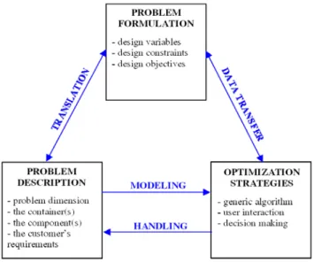
J. Cagan et al. proposed in [CS1] a schematic representation of the major constituent parts of a layout optimization problem. This paper suggests a new representation including three main
parts: the description of the problem, the formulation of the problem and the optimization strategies. As it is shown in the figure 1, these three parts are connected.
Figure 1: schematic representation of a layout problem.
Firstly, the problem description defines the dimension of the layout problem (one, two or three dimensions) and identifies the layout components, meaning the container and the components that have to be placed into the container. Secondly, this description and all the expert’s requirements have to be translated into design variables, constraints and objectives in order to change the layout problem into an optimization problem. Then, during the optimization process, the solving strategy continuously interacts with the formulation problem in order to compute the design constraints and the objectives. The optimization strategy can also include an interactive tool which allows the designer to interact with the process. Moreover, in order to visualize and modify the solutions, layout components are modelled according to the problem dimension.
IDMME - Virtual Concept 2010 Layout Optimization Problems
This paper describes these three parts which make up a layout problem. Sections 2 and 3 are respectively dedicated to the description and the formulation of layout problems. Section 3 also provides a definition of the complexity of layout problems. The optimization strategies are described in section 5. Section 6 concludes this paper.
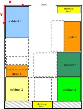
Moreover, in order to illustrate the concepts developed in this paper, a real-world layout problem is solved. This problem deals with the optimal spatial arrangement of facilities inside a shelter. Several components have to be located in the shelter, including electrical and energetic cabinets, desks and electrical boxes. The CAD model of the shelter is presented in the figure 2.
Figure 2: overall view of the shelter.
2- Layout problem description
The layout problem description is the first step of the global layout solving process. This step is usually defined by the engineering experts who well know the global performances of the product or the system. The layout problem description includes the description of the container, the components and the expert’s requirements. This section describes in particular the method used to describe layout components.
2.1 – Layout components attributes
This subsection defines some attributes used to classify layout components.
2.1.1 – “Material” and “Virtual” components
In layout problems, one finds at least one container and multiple components which have to be placed into the container. In some specific real-word layout problems, as the pallet loading problem, there can be more than one container. Layout components can be very different according to their shape, their size and their functional properties. For example, let us focus on the application studied in this paper. Let us consider that this problem can be conceptualized in two dimensions, because the cabinets are the full height of the shelter and prevent a superposition of elements. Its description is represented in the figure 3.
Figure 3: description of the shelter in 2D.
The cabinet 1 and the space in front of it (considering as the space of accessibility of the cabinet), represented by a dotted rectangle in the previous figure, are two components of this layout problem but can not be considered with the same way because of their different properties. In fact, these two components can be separated in “material” and “virtual” components, defined as:
- the material component: it has a mass and it can not overlap with an other material component. Layout components are generally considered as material components in layout literature [GF1,SC1],
- the virtual component: it has no mass and can overlap with some material or virtual components, according to the designer’s requirements. The passages, described in the layout problem presented in [LH1], can be considered as virtual components.
The example of the cabinet 1 shows that virtual components can be used to describe the space of accessibility of a material component, especially in the facility layout problems. In fact, the space of accessibility of a cabinet is defined as the required space to insert some materials into the cabinet.
As far as we know, the concepts of material and virtual components have not yet been used in layout design literature. However, they can have a significant impact on the description and the formulation of layout problems. For example, in the layout problem of the shelter, two material components can not overlap, whereas two virtual components (two spaces of accessibility) can overlap, considering that operations of materials loading are not simultaneous made.
2.1.2 – Components with variable shape and variable configuration
classified in two categories. Moreover, the layout problem of the shelter suggests that components can be sub-classified according to the following definitions:
- component with variable shape: the global shape and especially the dimensions of the component can change during the layout optimization process. In general, the dimensions of the component with variable shape are considered as design variables in the optimization problem,
- component with variable configuration: the configuration of the component changes during the optimization process but it’s not optimized. In the layout problem of the shelter, the desk 1 is a component with variable configuration because it can fall back. Then, we consider that it can overlap with the space of accessibility of the cabinet 1,
- invariable component: the global shape and the configuration of the component do not change during the layout optimization process. For example, the cabinets are invariable components.
2.2 – Layout components typology
As far as we know, there is no general typology of layout components. However, the layout components attributes, described previously, allow us to generate a general typology of these components. This typology is composed of six categories of layout components. For each category, an example is added according to the application studied in this paper:
- the Invariable Material Components (IMC): the cabinets, the electrical boxes and the desk 2,
- the Material Components with Variable Shape
(MCVS): there are no MCVS in the layout problem of
the shelter. However, if the dimensions of the cabinets were not fixed, the cabinets would be considered as MCVS,
- the Material Components with Variable
Configuration (MCVC): the desk 1,
- the Invariable Virtual Components (IVC): the spaces of accessibility of the cabinets,
- the Virtual Components with Variable Shape (VCVS): there are no VCVS in the layout problem of the shelter. In the architectural layout problem described in [MC2], the dimensions of each room are optimized. Then, the rooms are considered as VCVS,
- the Virtual Component with Variable Configuration
(VCVC): the space of accessibility of the desk 1.
Actually, this new classification of layout components can be used in order to propose a new typology of layout problems.
3– Layout problem formulation
The formulation of layout problems can use single or multi-objective optimization. The designer can make an early decision by using an aggregation function in order to transform a multi-objective problem into a single one. This approach is only effective when all data and information on the aggregation are available or if the designer is familiar with the specific layout problem. In this paper, we use multi-objective optimization. The decision on the preferences between
objective functions is delayed so that the designer can use the Pareto-front in order to select the most appropriate solution. After providing some information about multi-objective optimization, this section describes the method which allows the designer to formulate a multi-objective optimization problem. The complexity of layout problems is also explained in this section.
3.1 – The layout problem: a multi-objective optimization problem
The general formulation of a multi-objective problem can be written as follow: ⎪ ⎩ ⎪ ⎨ ⎧ ≤ = = = = nd : s.t argmin argmin variables design the find a ( ) 0 0 ) ( )) ( ),..., ( ), ( ( ) ( ) ,..., , ( : 1 2 2 1 x x x x x x x x * * h g f f f F x x x P porblem m n (1)
where m is the number of objective functions and n the number of design variables.
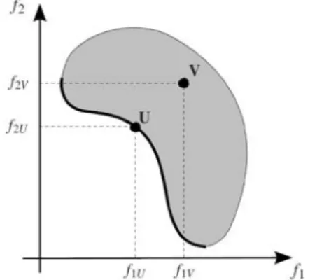
In this approach, the designer has to simultaneously optimize two or more conflicting objectives subject to constraints. In fact, the expert has to compare two solutions represented by two vectors of objectives FU =(f1U,f2U,...,fmU) and
) ,..., ,
( 1V 2V mV
V f f f
F = where FiU is the ith component of the
vector of objectives F for the design variable U. We consider that U dominates V (Pareto dominance) if U is as good as V for all the objectives and U is better than V for at least one objective. Mathematically, this can be formulated by: ⎪⎩ ⎪ ⎨ ⎧ < ∈ ∃ ≤ ∈ ∀ jV jU iV iU f f n j f f n i ] ,..., 1 [ ] ,..., 1 [
(2)
Multi-objective optimization searches for the set of non-dominated points (assimilated to Pareto-optimal points in the next sections of this paper) in the objective space given by efficient solutions. The figure 4 represents the Pareto front for an optimization problem defined by two objectives (min f1, min f2), where U dominates V .
IDMME - Virtual Concept 2010 Layout Optimization Problems
3.2 – The translation of expert’s requirements
The equation 1 shows that, in order to formulate an optimization problem, the designer needs three elements: the optimization variables, the design constraints and the objectives.
The design variables
Design variables are the parameters which can be modified by the designer in order to perform the global performances of the product or system. Their value will be fixed at the end of the optimization process. In most of real-world layout problems, the design variables are the variables which locate the components. For example, in the application studied in this paper, each component is defined by three optimization variables(X,Y,α): X and Y are continued variables that represent the coordinates of the center of gravity of a component and α is a discrete variable that defines the rotation angle along the Z axis.
Actually, the number of design variables per component defines the degree of freedom of the component. Some variables can be fixed in order to reduce the number of optimization variables. The opportunities of finding solutions in a reasonable time are then maximized. Besides, in some applications, the designer includes the dimensions of some components in optimization variables. These components are defined in section 2.1.2 as components with variable shape.
The design constraints and the objectives
Firstly, it is important to mention that constraints and the objectives can be exchanged according to designer’s requirements. Then, in the next subsection, the word “objective” can be used instead of “constraint”.
Two categories of design constraints are mainly considered: the geometric and functional constraints. In layout problems, the geometric constraints allow the detection of interference between two components. In fact, overlap between components has to be minimized in order to drive the current design into a feasible region. Since this collision detection is performed at each iteration of the solving algorithm, it is important to choose the appropriate geometric representation of the components and the efficient algorithm in order to reduce the calculation time. One can find in [LG1], a general survey of the main detection collision methods.
In the layout problem of the shelter, four non-overlap constraints are defined in order to detect the interferences between components:
- non-overlap constraint between material components (C1),
- non-overlap constraint between material and virtual components (C2),
- non-overlap constraint between components and the exterior of the shelter (C3),
- non-overlap constraint between cabinets and the space below the air-conditioner (represented by a hatched rectangle in the figure 3) (C4).
Actually, if the design constraints and objectives of a layout
problem are only geometric constraints, the application is generally compared to cutting and packing problems (C&P) [D1, WH1].
On the other hand, one can define functional constraints which formulate the different expert’s requirements and guarantee the functioning of the product or the system. Functional constraints are multiple in a layout problem: mass distribution, minimum or maximum distance between components, alignment of components, accessibility... In the layout problem of the shelter, three objectives are specified:
- one objective to balance the masses inside the shelter (by minimizing the distance between the center of gravity of the components and the geometric center of the shelter),
- one objective to maximize the distance between the energetic and electrical networks (by maximizing the distance between the cabinets 2 and 3, the box 2 and the cabinet 1),
- one objective to minimize the distance between the box 2 and one of the walls of the shelter, in order to establish a connection with exterior.
3.3 – The layout problem: a complex problem
Because of the great complexity of most real-world layout problems, the decision of an acceptable layout is a hard and critical task. In fact, the search of a “feasible” design, it means a design which respects all the design constraints, is time consuming because layout optimization problems are usually non-linear and NP-hard problems. It means that the problem is intrinsically harder than those which can be solved by a nondeterministic Turing machine in polynomial time. However, the concept of complexity of layout problems is a vague notion and, as far as we know, one can not find a general definition of the complexity (hardness) of layout design. Then, according to the description and the formulation of problems, this subsection defines this concept of complexity, by dividing it in three categories:
- the complexity linked to the geometry of
components: because of the irregular shape of some
layout components, the interference calculation between two elements is time consuming. This complexity is a computational complexity,
- the complexity linked to the layout problem density: the problem density is the ratio between the space occupied by the components and the total volume of the container. The bigger the problem density, the more difficult the search of a “feasible” design. If we only consider the material components in the layout problem of the shelter, the layout problem density is equal to 51,3%. It is more difficult to estimate the real density of this problem by also considering the virtual components.
- the complexity linked to the problem formulation: actually, more numerous the constraints and objectives, more complex the search of a feasible design, because of the parcelling of the design space. In order to pass to a feasible region to an other one, the designer can not use traditional gradient-based optimization approaches. He has to use stochastic algorithms as genetic algorithms. The calculation time then increases because
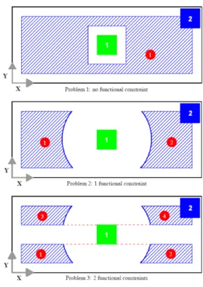
the problem is more complex. This formulation complexity is illustrated in figure 5 with a simple layout problem.
The layout problem, represented in the figure 5, consists of searching the optimal location of the component 2 in the black rectangular container whose dimensions are defined by H along Y and L along X. Let us consider a fixed component 1 located in the center of the container. The coordinates of the center of gravity of the component i is defined as(xi,yi). The
design variables are the coordinates(x2,y2).
Each problem described in the figure 5 has a non-overlap constraint between the two components and only one objective: maximize the distance between the component 2 and the bottom left corner of the container. Actually, the problem 3 is more complex than the problem 2 which is more complex than the problem 1 because:
Figure 5: example of formulation complexity.
- Problem 1: no functional constraint is defined. The design space (region of feasible solutions) is defined as only one region represented in blue hatched area.
- Problem 2: one functional constraint is added (d12= (x1−x2)2+(y1−y2)2 ≥D). The design space is
then divided in two parts.
- Problem 3: one other functional constraint is added ( y1−y2 ≥h). Each feasible region of the problem 2 is
divided in two parts. The design space is then composed of 4 regions, so that the search of the optimal solutions is more complex.
This example is a simple layout problem with only one container and two components. However the layout problems
can be very complex when the number of components and design requirements increases.
4– Optimization strategies for solving layout problems
This section presents a survey of the main approaches used for solving layout problems and proposes in particular an interactive generic strategy based on the genetic algorithm.
4.1 – A survey of solving approaches
One finds multiple search algorithms to solve layout optimization problems in two or three dimensions. Traditional optimization approaches for three dimensional layout problems are described by Cagan et al. [CS1]. They use genetic algorithms [YF1], simulated-annealing algorithms [SC2] or extended pattern search algorithms [SC3]. Most search algorithms are developed for a specific problem and they provide an effective optimization strategy for it. Therefore, they are not generic and can not be adapted to a lot of layout problems.
However, one can find other techniques which are more generic. For example, let us focus on the method described by Jacquenot et al. in [JB1]. The design strategy uses a Genetic Algorithm coupled with a Separation Algorithm. The structure of the algorithm is very closed to a generational genetic algorithm. The separation algorithm is nested in the genetic algorithm, and modifies the component positions so that the solution proposed respect placement constraints. Actually, before evaluating a solution, the algorithm checks if placement constraints are satisfied. If so, the different objectives of the solution are evaluated and the algorithm moves to the next solution. Otherwise, the separation algorithm is run and modifies the solution so that placement constraints are respected. The solution is then evaluated. Applications of the proposed method can be found in engineering domains, where placement problems have no particular specificity and can not be treated with classical methods.
4.2 – User interaction in layout design
In general, the development of an engineering object is considered as a single process involving multi-criteria identification of the mathematical model followed by multi-criteria optimization of the object design on the basis of this mathematical model. The process of statement-solution of engineering design problems without the interference of the design is impossible. For solving the design problem, the designer almost always has to correct either the mathematical model, the dimension of the vectors of design variables and criteria, the design variable ranges, and so on. The direct participation of the designer in the construction of the feasible design and non-formal analysis are the essential stage of the search for the optimal design.
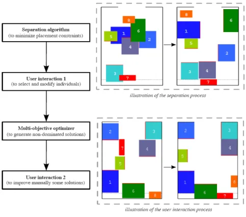
This paper presents an innovative interactive strategy for solving layout problems. The strategy, based on the generic method developed by Jacquenot et al. [JB1], uses four steps,
IDMME - Virtual Concept 2010 Layout Optimization Problems
whose two interactive stages:
- the first step consists of randomly initializing some designs and then optimizing it by the separation algorithm, considering only the geometrical non-overlap of components,
- in the second step, the designer interacts with the population generated by the separation algorithm by locally selecting and modifying some solution according to his personal judgment. The two first steps consists of
generating a customized initial population for the genetic algorithm,
- the third step consists of generating, by the genetic algorithm, a set of non-dominated solutions. The algorithm is stopped after a fixed number of iterations. The genetic algorithm used in this paper is described by Deb et al. in [DT1].
- In the last step, the designer visualizes and locally modifies some solutions by using an interactive
Figure 6: Interactive solving strategy for layout problems.
numerical environment. Then, the designer can improve the global performances of the solutions and take into account his personal judgment in order to make a final decision.
The figure 6 represents the four steps of this interactive optimization strategy. Two illustrations of the separation process and the second user interaction process are added in the figure 6.
Moreover, other user interaction steps could be directly inserted in the multi-objective optimizer, according the designer requirements:
- qualitative fitness or user perceptions could be inserted into design process [PP1]. In some layout problems, all constraints and objectives can not be easily formulated as simple mathematical expressions. It means that these constraints and objectives could be replaced by subjective criteria, defined by the designer in order to characterize the design. For example, this qualitative fitness could be represented by a mark and considered by the algorithm as a design objective. Brintrup et al. have
already developed an interactive genetic algorithm based framework for handling qualitative criteria in design optimization [BR1],
- the designer could interact with design variables during the optimization process. Stopping the optimizer would allow the designer to firstly analyze a specific solution, secondly locally modify the design configuration and then decide to keep this modified design in the next generation of the genetic algorithm. We can find in [MP1] a significant contribution to this concept applied to the design optimization of architectural layouts.
4.3 – Results obtained for the layout problem of the shelter
This subsection presents the results, obtained by the interactive optimization process described in the previous subsection, for the layout problem of the shelter. Firstly, the separation algorithm has been randomly initialized with 500 designs that didn’t respect non-overlap constraints. Then, these designs have been optimized by the separation algorithm. By interacting directly with them and by relaxing the design constraints (until 150 cm2), the
designer has selected 78 different optimized designs. This population then has been completed with 162 individuals randomly generated in order to create the first population of the genetic algorithm (240 individuals) and to guarantee the diversity of individuals.
Then, the Multi-Objective Genetic Algorithm has searched optimal solutions by considering the design constraints and all the objectives of the problem. Then, after one hundred of generations, a set of 14 feasible (meaning that respect the design constraints) variants have been computed. In fact, design j is a new variant if it differs from the design i by at least one of the following criteria:
- one of the components of the layout has been displaced from at least Δ mm along one of the axis
X and Y (Δ is fixed to 500mm in this simulation), - one of the components has been rotated,
- the minimum difference between the objective values of the two designs is bigger than a limit, fixed to 10 cm.
The numerical values, used to specify these three criteria, are subjective data. Then, these data have to be defined by the designer, who is the only person who is able to differentiate two solutions.
Among the 14 variants, 7 are Pareto-optimal designs but did not dominate the initial solution created by the expert engineers. This initial solution is an intuitive solution which has been generated only by considering geometric aspects. The initial solution neither dominates the designs computed by the algorithm.
Consequently, it means that the designer is the only person who can make the final design choices. In order to make a decision, the optimization strategy described in this paper proposes to use an interactive graphical and numerical environment. The main objective of this interactivity with the designer is to improve the global performances of the optimal solutions generated by the algorithm, by inserting, in the decision making, the personal judgment of the designer. Actually, the designer explores these 7 non-dominated variants, compares their objective values and selects one solution. Then, he interacts with this solution. By locally changing the location of some components of the shelter, as it is shown in the second illustration of the figure 6, the designer improves the global performances of the design. In fact, the solution modified by the designer is better than the initial solution, according to the formulated objectives.
5– Conclusion
The paper proposes an innovative approach to help the designer to describe, formulate and solve a layout optimization problem. It includes a new classification of layout components by introducing the concept of material and virtual components. Moreover, this paper proposes an interactive generic strategy for solving layout problems and emphasizes the fact that user interaction is an
important step of the global layout optimization problem.
6– Acknowledgment
The authors would like to acknowledge Thales Communications for the application study.
7– References
[BR1] Brintrup A.M., Ramsden J. and Tiwari A. An
interactive genetic algorithm-based framework for handling qualitative criteria in design optimization. Computers in Industry, 58, pp. 279–291. 2007.
[CS1] Cagan J., Shimada K. and Yin S. A survey of
computational approaches to the three-dimensional layout problems. Computer-Aided Design, 34, pp. 597–611. 2002.
[D1] Dyckhoff H. A typology of cutting and packing
problems. European Journal of Operational Research, 44(2), January, pp. 145–159. 1990.
[DP1] Drira A., Pierreval H. and Hajri-Gabouj S. Facility
layout problems: A survey. Annual Reviews in Control, 31, pp. 255–267. 2007.
[DT1] Deb K. and Tiwari S. Omni-optimizer: A generic
evolutionary algorithm for single and multi-objective optimization. European Journal of Operational Research, 185, pp. 1062–1087. 2008.
[GB1] Giassi A., Bennis F. and Maisonneuve J.-J.
Multidisciplinary design optimisation and robust design approaches applied to concurrent design. Structural and Multidisciplinary Optimization, 28, pp. 356–371. 2004.
[GF1] Grignon P.M. and Fadel G.M. A GA based
configuration design optimization method. Journal of MechanicalDesign, 126, pp. 6–15. 2004.
[JB1] Jacquenot G., Bennis F., Maisonneuve J.-J. and
Wenger P. 2d multi-objective placement algorithm for free-form components. In Proceedings of ASME 2009 International Design Engineering Technical Conferences & Computers and Information in Engineering Conference IDETC/CIE. 2009.
[LG1] Lin M.C. and Gottschalk S. Collision detection
between geometric models: A survey. In Proceedings of IMA Conference on Mathematics of Surfaces, pp. 37–56. 1998.
[LH1] Lee K.-Y., Han S.-N., and Roh M.-I. An improved
genetic algorithm for facility layout problems having inner structure walls and passages. Computers Operations Research, 30(1), pp. 117–138. 2003.
[MC1] Mead C. and Conway L. Introduction to VLSI
Systems. Addison-Wesley Longman Publishing Co., Inc. 1979.
[MC2] Michalek J.J., Choudhary R. and Papalambros P.
Y. Architectural layout design optimization. Engineering Optimization, 34, pp. 461–484. 2002.
IDMME - Virtual Concept 2010 Layout Optimization Problems
[MP1] Michalek J.J., and Papalambros P. Y. Interactive
design optimization of architectural layouts. Engineering Optimization, 34, pp. 485–501. 2002.
[PP1] Poirson E., Petiot J.-F. and Gilbert J. Integration of
user-perceptions in the design process: application to musical instrument optimisation. Journal of Mechanical Design, 129, pp. 1206–1214. 2007.
[SC1] Su Y. and Cagan J. An extended pattern search
algorithm for three-dimensional component layout. Journal of Mechanical Design, 122, pp. 102–108. 2000.
[SC2] Szykman S. and Cagan J. Constrained
threedimensional component layout using simulated annealing. Journal of Mechanical Design, 119, pp. 28–35. 1997.
[SC3] Su Y. and Cagan J. An extended pattern search
algorithm for three-dimensional component layout. Journal of Mechanical Design, 122, pp. 102–108. 2000.
[WH1] Wascher G., Haubner H. and Schumann H. An
improved typology of cutting and packing problems. European Journal of Operational Research, 183, pp. 1109– 1130. 2007.
[YF1] Yi M., Fadel G.M. and Gantovnik V.B. Vehicle
configuration design with a packing genetic algorithm. International Journal of Heavy Vehicle Systems, 15, pp. 433–448. 2008