* w * * *
* *
ISSN 1018-5593
Commission of the European Communities
technical steel research
Practical design tools for unprotected steel
columns submitted to ISO-Fire — Refao
Commission of the European Communities
- £ ? i
Practical design tools for unprotected steel
columns submitted to ISO-Fire - Refao III
Arbed - Recherches
66, rue de Luxembourg L-4221 Esch/Alzette
Contract No 7210-SA/505 (1.7.1986-31.12.1989)
Final report
Directorate-General Γ Ρ ADI cno^D^D-i I- I
Science, Research and Development
rAKI.bJKüP, Bifaliolh.
Published by the
COMMISSION OF THE EUROPEAN COMMUNITIES Directorate-General XIII
Information Technologies and Industries, and Telecommunications L-2920 Luxembourg
LEGAL NOTICE
Neither the Commission of the European Communities nor any person acting on behalf of the Commission is responsible for the use which might
be made of the following information
C.E.C. Agreement N° 721 OSA/505
PRACTICAL DESIGN TOOLS FOR UNPROTECTED
STEEL COLUMNS SUBMITTED TO ISO-FIRE
REFAO-m
Period from 01.07.1986 to 31.12.1989
FINAL REPORT
Parts Ι-Π-Π
RPS Report N° 11/91
ABBED-Recherches
66, rue de Luxembourg
L - 4221 ESCH/ALZETTE
C.E.C. Agreement N° 72IOSA/505
PRACTICAL DESIGN TOOLS FOR UNPROTECTED
STEEL COLUMNS SUBMITTED TO ISO-FIRE
REFAO-m
Period from 01.07.1986 to 31.12.1989
FINAL REPORT
RPS Report N
311/91
DEPARTMENT MANAGER J.B. SCHLEICHIngénieur Civil des Constructions Ingénieur principal
PROJECT MANAGER J. MATHIEU
Ingénieur Civil des Constructions P. CHANTRAIN
Ingénieur Civil des Constructions L.-G. CAJOT
Ingénieur Civil des Constructions
Service Recherches et Promotion technique Structures' (RPS) AREED-Recherches 66, rue de Luxembourg L-4002 ESCH/ALZETTE LUXEMBOURG 05.06.1991
CONFIDENTIAL
TITLE OF RESEARCH: Practical design tools for unprotected columns submitted to ISO-Fire
AGREEMENT:
EXECUTIVE COWHTTEE:
COMMENCEMENT OF RESEARCH: SCHEDULED COMPLETION DATE:
tf 7210-SA/505 F 8
01.07.1986 31.12.1988
ACKNOWLEDGEMENTS
This research consisting in the setting up of tables for the design of thick flanged steel columns submitted to ISOfire exposure with any fire protection has been performed by ARBED S.A. during the years 1986 to 1988 and sponsored by C.E.C., the Commission of the European Commu nity (C.E.C. Agreement N° 7210SA/505).
We want to acknowledge first of all the important financial support from the COMMISSION OF THE EUROPEAN COMMUNITY, as well as the moral support given this research by all the members of the C.E.C. EXECUTIVE COMMITTEE F8 "LIGHT WEIGHT STRUCTURES".
Special thanks are due to the collaborators of Professor Dr. Ir. R.
MINNE, Director of the Fire Laboratory of Gent University (Belgium), as well as to the collaborators of Professor Dr. Ir. Κ. KDRDINA, Director of the Fire Laboratory of Braunschweig University (Federal Republic of Germany). The six full scale fire tests on steel columns could all be executed successfully, thanks to the knowledge and the experience of the technical staff of these two laboratories.
We wish to record our appreciation of the efforts and cooperation of the specialists of Professor Dr.Ir. R. BAUS, Director of the Department for Bridges and Structural Engineering of Liège University (Belgium), and especially of Dr. Ing. J^î. FRÄNSSEN, for the improvement of the computer code CEFICOSS.
Thanks are finally due to all, who by any means may have contributed to this research programme, as for instance people of company GST in Essen (Germany), who performed the transient state beam tests described in Part III.
"Practical design tools for unprotected steel columns submitted to
ISO-fire"
Agreement JV° 7210 - SA/505 Og.C. -ARBEP
SUMMARY
The main parameters to be considered in this research programmer i.e.
geometrical factors (shapes, buckling lengths), steel qualities and
coefficients governing the heat exchanges are presented first.
The temperature dependent stress-strain relationships of steel as
ini-tially existing in the program ŒFIC0SS have been tested by simulation
of bending tests described in the litterature. It has shown a necessity
to improve these laws when pure steel elements have to be calculated.
New improved stress-strain relationships of steel have been carried out
and calibrated thanks to transient state beam tests performed on small
simply supported steel beams, subjected to a concentrated constant
load, and submitted to a controlled temperature increase. These new
laws have been established as well for commonly used construction
steels as for high strength steel FeE 460.
The validity of these improved relationships has been next verified by
simulating very well six full scale fire tests performed on unprotected
steel columns in the laboratories of Braunschweig and Gent.
The possibility to take into account a distribution of residual
stres-ses has been introduced in CEFICOSS. The simulation of the six column
tests showed that residual stresses have a quite small influence of the
fire resistance time of columns. It has been decided, however, to
con-sider systematically a distribution of residual stresses in the
calcu-lations.
Practical design tools have been finally carried out and are proposed
in form of tables as well as diagrams.
"Outils pratiques de dimensionnement pour poutrelles-colonnes en acier
non protégé soumises à l'incendie".
Contrat JV° 7210 - SA/505 C.C.B. - ARBED
RESUME
Dans une première phase sont définis les paramètres essentiels à
intro-duire dans cette recherche, tels que les facteurs géométriques
(sec-tions, longueurs) et mécaniques (qualités d'acier), ainsi que les
coef-ficients relatifs aux échanges thermiques par radiation et convection.
Les lois de comportement thermomécanique de l'acier à haute température
existant initialement dans le programme ŒFICOSS ont été éprouvées par
des simulations d'essais décrits dans la littérature, ce qui a montré
la nécessité de les affiner dans le cas où des éléments purement
métal-liques doivent être simulés.
Des tests de flexion sur des petites poutres métalliques soumises à une
charge constante et à une élévation de température (uniforme) régulière
à vitesse contrôlée, ont permis de calibrer de nouvelles lois
d'évolu-tion des propriétés métalliques de l'acier en foncd'évolu-tion de la
tempéra-ture, aussi bien pour les aciers courants de construction que pour
l'acier FeE 460 à haute limite élastique.
La validité de ces nouvelles lois a pu être ensuite vérifiée grâce à la
simulation de six essais au feu en grandeur réelle réalisés sur des
colonnes nues à Braunschweig et à Gand, et ensuite parfaitement simulés
par ŒFICOSS.
Ensuite, la possibilité de prendre en compte une répartition de
con-traintes résiduelles a été introduite dans ŒFICOSS. Les simulations
des six tests ont démontré que ces contraintes résiduelles n'ont pas
une très grande importance sur le temps de ruine final, mais il a été
néanmoins décidé de les prendre en compte dans tous les calculs.
Praktische Bemessungshilfen für die Interaktion von Normalkräften (N)
und Biegemomenten (M) für Stahl-Beton Verbundelemente unter
Feuerbean-spruchung (ISO - Kurve)
Vertrag JV° 7210SA/505 KEG-ARBED
ZUSAMMENFASSUNG
Die erste Phase dieser Forschungsarbeit behandelt die Bestimmung der
wesentlichen einzugebenden Parameter. Diese Parameter bestehen aus
geo-metrischen Faktoren ((Querschnitt, Länge) und mechanischen Faktoren
(Stahlgüte), sowie aus den relativen thermischen Austauschkoeffizienten
verursacht durch die Wärmeausstrahlung und Konvektion.
Die thermomechanischen Gesetze von Stahl bei hoher Temperatur
fwelche
anfänglich im Programm ŒFICOSS enthalten waren, wurden durch
Simula-tionsversuche gemäss Beschreibung in Literatur überprüft. Diese ergaben
die Notwendigkeit die Gesetze zu verfeinern im Falle der Simulation von
ungeschützten Stahlelementen.
Biegeversuche von kleinen Stahlprofilträgern beansprucht durch eine
konstante Einzellast und einer gleichmässig ansteigenden Temperatur
haben es erlaubt, neue Gesetze über die metallischen Eigenschaften von
Stahl unter Temperatureinfluss zu entwickeln, welche für geläufige
Stahlgüten in der Baukonstruktion und ebenso für Stahl FeE 460 mit
hoher Streckgrenze anwendbar sind.
Die Gültigkeit dieser neuen Gesetze kann auf Grund der Simulation von
sechs Versuchen (Massstab 1:1) unter Feuerbeanspruchung an
ungeschütz-ten Stahlstützen in Braunschweig und in Gent bestätigt werden und
konn-ten nachträglich mit ŒFICOSS simuliert werden.
Ausserdem wurde im Programm ŒFICOSS die Möglichkeit gegeben
Eigenspan-nungen zu berücksichtigen. Die Simulation der sechs Versuche hat
bewie-sen, dass diese keinen grossen Einfluss auf das Endergebnis haben, sie
wurden jedoch in allen Berechnungen berücksichtigt.
Schliesslich wurden praktische Bemessungshilfen, auf Grund von
ŒFI-COSS-Simulation, in Form von Diagrammen und Tafeln erstellt.
CONTENTS
SUMMARY 1. 2. 3. 4. 5. PART I: REPORT INTRODUCTION1.1. Thermo-mechanical computer model CEFICOSS 1.2. Aim of research
1.3. General scope on the parameters FACTORS GOVERNING THE BEAT TRANSFER 2.1. Heating-curve
2.2. Coefficient of convection 2.3. Resultant emissivity
2.4. Thermal properties of steel THERMO-MECHANICAL MATERIAL PROPERTIES
3.1. Initial stress-strain relationships of steel 3.2. KRUPP test
3.3. Simulation of four tests by CEFICOSS 3.4. Comparison with test results
3.5. Conclusion
BEHAVIOUR OF STEEL UNDER TRANSIENT STATE BEAMS TESTS BEAMS TESTS
4.1. Description of the new tests (SI to S10) 4.2. Results of these tests
4.3. Simulation with CEFICOSS using the known Fe360 steel RS-LAW
4.4. Conclusion of the simulations 4.5. Improvements of steel laws
4.6. Additional tests (Sil, S12, VI to V7) IMPROVED QL-LAWS
5.1. Definition of the new QL-laws
5.2. Simulation of KRUPP tests with the new QL-laws 5.3. Comparison of the CEFICOSS results with the
measures
5.4. Conclusion of the simulations
Page
1
1·
2
3
3
3
4
5
5
6
7
7
8
9
10
12
12
13
14
14
15
18
Pages
6. FULL-SCALE TESTS OF COLUMNS
6.1. Description of the columns 6.2. Results of the tests
6.3. Simulation of the six full scale tests with CEFICOSS
6.4. Conclusions
7. PARAMETERS
7.1. Selection of steel shapes 7.2. Bending moment distribution 7.3. Buckling lengths
7.4. Design strength of steel
7.5. Calculation with CEFICOSS in normal service conditions
7.6. Initial imperfection introduced in CEFICOSS 7.7. Failure criterion
7.8. Influence of residual stresses
8. DIAGRAMS
8.1. Calculation process 8.2. Diagrams
8.3. Interpolation on buckling lengths
8.4. Transformation method for non uniform moment distribution P. CONCLUSIONS 18 19 20 20 21 21 21 22 22 23 24 25 26 26 27 27
28
10. BIBLIOGRAPHYPART II: DIAGRAMS Alt) TABLES
30
PART I
I. INTRODUCTION
1.1. Thermo-mechanlcal computer model CEFICOSS
During the C.E.C, research, agreement N° 7210-SA/502 [1], a computer program for the analysis of steel as well as compo-site structures under fire conditions has been developed. It is based on the finite element method using beam elements with sub-division of the cross section in a rectangular mesh. The struc-ture submitted to increasing loads or temperastruc-tures is analysed
step-by-step using the Newton-Raphson procedure. The thermal problem is solved by a finite difference method based on the heat balance between adjacent elements.
The numerical simulation of several full scale fire tests per-formed during various research projects ([1], [2], [3], [4]) has demonstrated that this numerical software CEFICOSS is able to simulate in a correct way the structural behaviour of ele-ments submitted to fire and provides a pretty good estimation of the fire resistance times. CEFICOSS is a tool which allows most credible prediction of the fire resistance of structural ele-ments, and which can be used particularly for steel columns, with or without fire protection.
1.2. Aim of research
Tests performed at the University of Gent [1] on thick flanged steel columns made clear that a high massivity - the
section factor F/V of the steel profile was 27 m_1
-provides a good fire resistance even to bare steel profiles. Only numerical models giving the temperature gradient through profile section are able to predict correctly the behaviour of
such thick bare steel elements.
Indeed during the test of an unprotected column a fire resis-tance time of 45 minutes was measured while the simulation by CEFICOSS gives 46 minutes. This column was loaded at a level corresponding practically to the maximum allowable in normal service conditions, and would not have reached the fire resis-tance class F30 according to the usual simple calculation method based on the assumption of an uniform temperature inside of the steel section and on the conservative stress-strain-relation-ships of the ECCS-Recommendations [5].
In order to make the results of this computer code available for everybody, it has been decided to establish N-M interaction dia-grams for unprotected steel columns made of massive steel H-shapes.
The research programme has been based on six fire tests per-formed in the furnaces of Gent and Braunschweig and, from the other hand, on the intensive use of the thermomechanical numeri-cal code ŒFICOSS to numeri-calculate massive shapes (HD and HEM series) in a parametrical way.
This Final Report summarizes the works performed during the pre-vious research periods and described in the Technical Reports N° 1 to 5 ([6], [7], [8], [9], [10]).
1.3. General scope on the parameters
The parameters to be introduced in this research are summarized as follows:
Section: The profiles from HEM and HD series with a flange thickness of at least 40 mm
Finally the following sections are concerned in this programme: HEM 320 up to 1000
HD 210x210x198 to 249 HD 260x260x219 to 329 HD 310x310x283 to 500 HD 400x400x314 to 1086 Steel grades: Fe 510 and FeE 460
However sections with flange thickness higher than 40 mm are not actually usual in quality FeE 460 and therefore this steel qua-lity will be reserved for HEM series.
2. FACTORS GOVERNING THE HEAT TRANSFER
2.1. Heating curve
All the calculations performed in this research have been made
with the ISO834 [11] standard heating curve/ giving a gas
temperature varying as follows around the heated element: Tg = 20 + 345 log10 (8t + 1)
With t = fire time in minutes.
2.2. Coefficient of convection
Following the recommendations of Technical Committee 3 of the
ECCS [5] it was decided to make all the calculations in this
research programme with a value α = 25 W/m2.K for the convection heat transfer.
2.3. Resultant emissivity
The value of the resultant relative emissivity ε* to be introd uced in CEFICOSS can usually vary between 0.45 and 0.7 depending of fire test conditions, and also normally varies during a test with temperature.
As suggested in the recommendations of the ECCS [5], one
constant value ε* = 0.5 could be used for steel surfaces.
However the full scale test done at the University of Gent
[1] showed that the temperature in the middle of the web can only be satisfactorily calculated by choosing a resultant emis sivity ε* smaller for the inner surfaces in chambers as for the
outer ones, thus simulating the radiative shadow effect (see
figure 2.1).
The resultant relative emissivity ε* in the concave part of a Ηsection can be calculated as follows according to [12]:
e
*web
= ε* · ^ ^
The coefficients Fweb and Fflange are given by: Fweb = - (b/2-a/2) + V (h-2e)2 + (b/2-a/2)2
(h-2e)
Fflange = (h-2e) + (b/2-a/2) - V (h-2e)2 + (b/2-a/2)2 (b-a)
where h, b, a and e are dimensions of the steel shape height, width, thickness of the web and thickness of the flange.
The values of ε* for the web and for the inside part of the
flanges, and corresponding to ε* = 0.5 for the outside face of the flanges, have been calculated for each shape concerned in this research.
For HD sections ε* varies from 0.182 up to 0.188 for the inside face of the flange, whereas ε* varies from 0.286 up to 0.301 for the web.
For HEM sections ε* of the inside face of the flange increases regularly from 0.189 to 0.231 for shape increasing from 320 up to 1000, and an average value of 0.2 is not far away from the reality.
As concerns the web, the value of ε* increases regularly from 0.305 to 0.43.
Therefore it seems reasonable as simplification to adopt for any section the following resultant relative emissivity:
ε*
ε*
ε*
= = =0
0
0
.5
.2
.3
for outside for inside for the webfaces faces of the of the flanges flanges
and all the calculations have been performed according to figure 2.1.
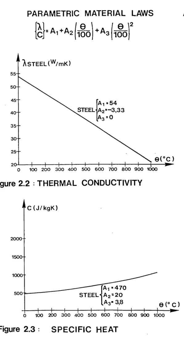
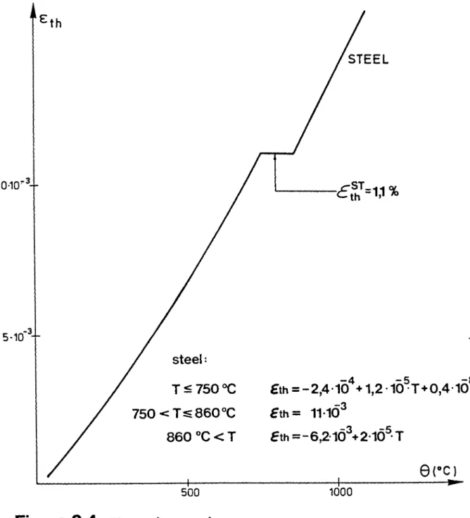
2.4.
Thermal properties of steel
3. THERMO-MECHANICAL STEEL PROPERTIES
3.1. Initial stress-strain relationships for steel
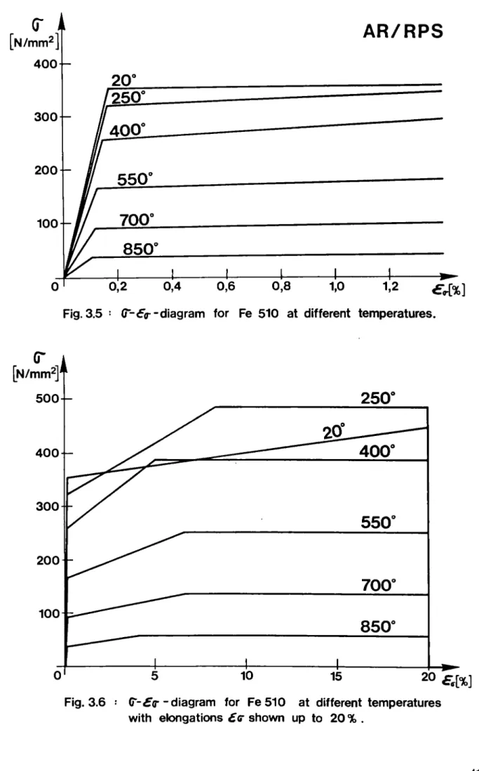
The laws describing the temperature dependent stress-strain relationships of steel are given in figure 3.1 to 3.6 as exis-ting initially in CEFICOSS (see [1] ). These laws have been established for usual construction steels like Fe 360 and Fe 510 and mainly for calculation of composite sections. It was to be examined, whether these temperature-dependent stress-strain relationships are too much simplified for simulating unprotected bare steel columns.
Furthermore the behaviour at high temperatures of steel FeE 460 had not yet been calibrated before, and it was reasonable to fear a different behaviour of this steel in fire owing to the fact that his properties are obtained by a thermomechanical treatment.
3.2. KRUPP tests
First of all it was interesting to try to find in the littera-ture some reports over tests performed on pure steel elements and covering as far as possible the field of strains interesting in this research. This possibility was given by bending tests performed by Rubert and Schaumann [13] in KRUPP Research Centre in order to investigate the properties of steel in fire, and it has been decided to simulate some of these tests with CEFICOSS.
These bending tests on profiles IPE 80 are schematically ex-plained in figure 3.7. The beam with a span of 114 cm is situa-ted inside of an electrical furnace, and subjecsitua-ted to a external point load F which is kept constantly during the test. After
loading, the temperature inside of the small electrical furnace increases continuously with a given velocity. Because of the small thickness of the profile IPE 80, the temperatures can be considered as uniform inside of the steel section, and the ther-mal expansion of steel has practically no influence on the ver-tical deflection, which is registred at mid-span of the beam during the test. This type of test has been performed in KRUPP Research Centre for different loading rates F/Fplastic, and for different heating velocities. Process and results of these tests are described in [13] and [14].
3.3. Simulation of four tests by CEFICOSS
Four tests, called WK1 to WK4 and described in the reports
[13] and [14] have been simulated with CEFICOSS with the
existing stressstrain relationships, and with the following
assumptions :
1) The dimensions of sections have been assumed to be constant and equal to the theoretical dimensions of an IPE 80. This assumption is justified by the very small differences mea sured by Rubert & Schaumann in tests and presented in the report [14]:
Average of differences on the inertia: 0.93 %
Average of differences on the plastic moment: 0.88 %
2) The curves giving the actual measured variation of tempera
ture during tests are not given in [13]. The authors
give just for each test a mean value of the heating veloci ties which are very close to the theoretical one (the high est difference for tests WK 1 to WK 4 reaches 5 % ) . Moreo ver, a conclusion of all the tests presented by the authors is that the heating velocity doesn't play an important role on results. Therefore the tests may logically be simulated with the theoretical temperature curve presented in figure 3.8.
3) All the temperatures mentioned in [13] are steel tempera tures and not gas temperatures. Therefore, the statical cal culations in CEFICOSS have been performed with effectively given steel temperatures.
4) The mechanical properties of steel used in CEFICOSS were
taken from the report and are measured values: Oy =35.2 KN/cm2 for the test WK1
Oy =39.9 KN/cm2 for the test WK2
Oy =39.9 KN/cm2 for the test WK3
3.4. Comparison with test results
The curves D=f (t) given by CEFICOSS in the four simulations have been transformed into the form D=f(T) using the relation T=f (t) defined earlier in figure 3.8. These curves D=f (T) are given in figure 3.9 together with the actual measured displacements.
For tests WK1 to WK3, CEFICOSS gives smaller displacements than measured up to a certain temperature. Over this critical point, the displacements given by CEFICOSS are larger than the measured ones. This critical temperature (for D=40 mm) increases when the rate of loading decreases, and the differences between CEFICOSS
and tests go down progressively. For test WK4, which has the
lowest load, CEFICOSS gives lower displacements for any tempera ture.
To sum up, the pseudovertical (assymptotic) curves given by
CEFICOSS for high displacements go progessively from the left side of the measured curves to the right side when the rate of loading decreases. The crossing point can be roughly defined by Τ ~ 600°C or F/Fp 0.50.
Up to about 600°C, CEFICOSS gives results which are conservative for a design based on the plastic moment, but they seem to be unsafe for higher temperatures.
In the intermediate zone of lower temperature, where the curves turn from small to high, displacements, the existing laws give deflections always smaller than measured in tests and seems to be clearly unsafe.
3.5. Conclusion
The last notice before is very important for the present
research. As a matter of fact, the form of the (σ€) diagram in the intermediate zone just before to reach the plastic plateau has an important influence on the buckling behaviour of columns. The comparison done here shows that the σe relationships inclu
ded in CEFICOSS should be improved to perform calculation of
4. BEHAVIOUR OF STEEL BEAMS UNDER TRANSIENT STATE BEAM TESTS
4.1. Structural steel qualities
Tests «described in [13] have been performed on beams theore-tically in Fe 360, but steels were rather of quality Fe 510 according to their yield strengths (see § 3.3). These tests can obviously be considered to cover the quality Fe 510, and the highest quality FeE460 was to be investigated too, in a same way, in the same testing device by KRUPP (figure 4.1).
In the previous bending tests, IPE 80 profiles were used; for steel FeE460, however, such profiles are not rolled and similar sections had to be manufactured. The test pieces have been extracted from a FeE460 steel beam W 360x410x314 in its 40 mm thick flanges (see figures 4.2). The tests take aim at measures of mechanical properties of steel at high temperatures, so that's why it was important to reduce as much as possible the heating of steel during the tooling, with adapted machine speed and cooling. The cuttings have been made preferably by sawing than with blowtorch.
The bending tests in themselves are schematically explained on the figure 4.1 and more detailed in Appendix A of part III. The simply supported beam with a span of 114.7 cm is situated inside an electrical heating furnace, and subjected to an external point load F which is applied at the middle of the span and kept constant during the test. After loading, the temperature induced by the electrical resistance increases continuously with a given velocity.
Because of the small thickness of the manufactured profile, the temperature can be considered as uniform inside the steel sec-tion and more, the thermal expansion of steel has practically no influence on the vertical displacement which is. registered at the middle of the beam during the test.
To control the assumption of a uniform temperature, thermo-couples have been placed on all the beams to record in different
The heating velocity has been chosen equal to 3.5 K/min; it has
been shown in previous tests [13] that variations of veloci
ty have no significant influence on results.
Nine tests of this type have been performed for different loa
ding rates F/Fpcold, where Epcold means the theoreti
cal necessary applied force to obtain the middlespan section
fully plastified (plastic hinge) with a birectangular stress
distribution (rigidplastic theory). The nine transient state
beam tests are called SI to S7, S9 and S10; S8 is a cold test with loadings and unloadings up to collapse.
1.2.
Results of the tests
The pages A5 to A13 of Appendix A, PART III, give the measured vertical displacements (mm) at the middle of the span in func tion of the temperature (°C), for the nine transient tests, in a decreasing order of loading levels.
The next page A14 shows the measured deflection at midspan of the beam in function of the load F, for the cold test S8.
The ten tests are summarized in figure 4.3 as well as in the
table of page A15 in Appendix A of PART III, giving the follow ing informations:
The yield point ßs has been determined with tensile test pie ces extracted from the flanges of the beam W 360x410x314 as shown on the figure 4.2 (T = specimens for tensile tests).
The different values of ßs appears in the column REH, the
superior elastic limits obtained by tensile tests·
Epcold' the theoretical necessary applied forces to
obtain the middlespan section fully plastified (plastic
hinge) with a birectangular stresses distribution (rigid plastic theory).
F, the applied loads
F / F P C O L D the loading levels
Øm, the mean velocities of heating
θ ^ ^ , the initial temperatures during the cold loa
(Gto)max' the maximal mean temperatures of the steel reached during the test (thermocouples measures)
~ (DmesJmax' t h e maximal vertical displacements at
the middle of the beam measured during the test
" ^test^max' ^ ^ duration of the test (not fire
resistance)
4.3. Simulation with CEFICOSS using the known Fe360 steel RS-LAW
The performed KRUPP tests have been simulated with the following assumptions :
1) All the dimensions of the cross section have been kept cons tant and equal to the theoretical dimensions of the tooled beams (see figure 4.1). This assumption is justified by the very small differences (lower than 3 %) produced on geometri cal and mechanical characteristics of the profile by tooling
tolerances of ± 1/10 mm (see page A16 of Appendix A, PART
III) .
The modélisation of a quarter of a beam section is presented on the page A17 of Appendix A.
2) Temperaturetime curves issued from mean measures β^[°ο]
between thermocouples TH5 and TH12 (see page A. 3), obtained for each test have been used for simulations. As explained
before, differences between measured temperatures are so
small that an uniform temperature can be considered every where through the cross section and along the beams.
Moreover in the previous KRUPP tests, the authors showed that
the heating velocity doesn't play an important role on
results and so it's the same for differences between all the temperaturetime curves with thermocouples for each test.
Therefore, the statical calculations have been performed with mean measured steel temperatures from TH5 and TH12 (see pages A13 and A19 of Appendix A ) .
the linear elastic, the elliptical elastoplastic and the plas tic plateau.
Figures 4.5, 4.6 and 4.7 give respectively the reduction of the elastic modulus factor Eo (Θ) /Eo (9=20°C), the proportional stress
factor pp (θ) /βρ (θ=20°Ο, and the yield point factor
ßs (θ) /ßs (9=2 0°C), in function of temperature, for steel Fe
360.
Figure 4.8 shows the resultant diagram with all the RSLAW cur
ves at different temperatures for steel FeE460 (ßg(e=20°C) =
460 N/mm2, for example) .
The results of the nine fire simulations SI to S10 and the only cold one S8 are given in Appendix A, PART III, pages A20 to A89 in a decreasing loading level order. The fire simulation figures represent the curve D = f(θ), the simulated vertical displace
ment ( ) the middle of the beam in function of the
temperature, compared with the measures ( ).
The cold simulation figure shows W = f (F), the same type of dis placement in function of the increasing load.
For the fire simulation of Ş1 test (loading level = 1.0; that
means a fully plastified middlespan section) CEFICOSS can't
give any results because the cold loading ends already with
problems of numerical convergence (plastic hing failure).
Indeed, the RSLAW ends with a plateau and so doesn't consider the strainhardening (see page A20).
The same remark can be made for the cold simulation of S8 test because the collapse load cannot be reached without strainhar dening. The failure load obtained with CEFICOSS is 30.6 kN, dif ferent in about 2.0 % of the calculated value from the rigid plastic theory, 31.3 kN. The difference between 30.6 kN calcula ted with RSLAW and the measured real failure load 37.65 kN is about 18%.
For the other fire simulations (S2 to S7, S9 and S10) it can be observed that CEFICOSS with Fe 360 RSLAW leads to a behaviour of the beams not too much different from reality. The results have especially good agreements in the field of usual loading
level concerning this research, in other words F/Fpcoid =
0.30 to 0.70.
For high or low loading level, for example 0.85 (S3 test) or
0.10 (S7 test) and 0.075 (S6 test), more important differences are found.
4.4.
Conclusions of the simulations
As
a matter of fact, the form of the (σβ) diagram in the inter
mediate zone just before to reach the plastic plateau has an
important
influence on the buckling behaviour of columns. All
the
comparisons done show that the σβ laws included in ŒFICOSS
should
be improved, especially for steel FeE460, when pure steel
columns are calculated.
4.5.
Improvement of steel laws
*
A first possibility to improve the existing (σβ) laws in
ŒFICOSS,
was to adapt the Fe360 RubertSchaumann law [13] to
the FeE460 steel quality, because the simulations with the
RSLAW
in ŒFICOSS are not too bad as shown before.
*
Another approach could be to take into account the strain
hardening
reality, by use of a simple type of diagram, a qua
drilinear law defined by the following temperaturedependent
parameters
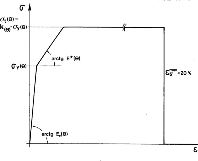
(see figure 4.9):
E
0Q, the elastic modulus.
=0,2
%
σ
νQ, the yield point.
E*ø, the elastic modulus relevant for strainhardening.
d| 0, the ultimate stress.
Such
a multilinear σε idealization, correctly done, would
have the advantage to cover conveniently all 10 tests (SI,
S3, S7 and S8 included).
In
other words:
*
the whole range of loading levels is covered i.e. 0.075 £
F//F
pcold
^ 1·0 corresponding to the critical tempera
.6. Additional tests (Sil, S12, VI to V7)
Additional tests have been performed in the same testing device; two of them (Sil and S12) have been performed in the plastic domain for steel FeE460, while seven tests (VI to V7) have been performed on small sections IPE80 in steel Fe360 (figure 4.10). As mentionned before, the initial KRUPP tests [13] have been performed on steel having 386 MPa as mean value of yield
strength at 20°C, while the specimens used here reach only 313 MPa. Thus the field of yield strengths has been fully covered. These tests are reported with details in the Appendix A of PART III, pages A30 up to A40
For steel FeE460, the procedure of testing applied for Sil and S12 consisted in starting at room temperature to load the beam, with F/Fp-.Q^ greater than 1.0; afterwards heating until a definite temperature with a constant load and finally heating and increasing the load of the beam together until collapse.
For steel Fe360 two tests have been perfomed in the plastic domain with the same procedure as explained before (VI and V2 tsts), while four tests have been performed in the elastic domain beginning with different F/Fp^^d strictly smaller than 1.0 and being heated with constant load until collapse (V4, V4, V5 and V6 tests). The V7 test is a cold test with loading
and unloading up to failure.
A sensitivity of beams to a well-known parasite phenomenon, the buckling (local buckling of the flanges; lateral--torsional buck-ling of the whole beam) has been observed, more especially for beams already fully plast if ied (F/Fcold £ 1.0) before hea-ting. Therefore the testing procedure has been adapted without changing its validity, in applying loads via a kind of knife edge and in welding by points some stiffeners on each side of the web, out of the middle-span of the beam (only this for V2 and S12 tests) (see details in Appendix A ) .
5.
IMPROVED QL-LAWS
5.1. Definition of the new QIAaws
To define such a modelization, as suggested in § 4.5 by figure 4.9, steady state tensile tests (SSTT) for FeE460 steel quality have been performed in the laboratory of ARBEDResearch. They consisted in tensile tests under constant high temperature in duced by an electrical furnace around the specimen. Some curves
(σ,ε) issued from these tests are shown in figures 5.1 and 5.2 with at the same time the QLIDEALIZATION.
It can be seen on these figures how the four main parameters have been found, respectively for 20°C and 400°C:
Ε
ο,θ
Eo,20C~<5,F*1 _ Γ 4 Ί
(
|~°Μ) "
_
°y,20°cj '
Eo,20°c]
' |__
(V,20°C
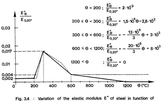
A more precise evolution of these parameters in function of the temperature 6[°C], for QLlaw concerning steel FeE460, can be found in figures 5.3 to 5.6. The figures 5.7 and 5.8 show the diagrams (σ,ε) of QLlaw for high strength steel with different curves corresponding to different given temperatures, respecti vely with ε increasing up to 4 % or 25 %.
5.2. Simulation of KRUPP test with the new QL-laws
All the KRUPP tests described in the previous chapter 4, called SI to S12 for steel FeE460 and VI to V7 for steel Fe360, have been simulated in CEFICOSS with the new QLlaws proposed above and with the following assumptions:
1) For simulations of SI to S10 tests (steel FeE460) the same geometrical dimensions have been taken for all the specimens because of the weak influence of the tooling tolerances on the geometrical and mechanical characteristics (see § 4.3).
For the simulations of tests Sil, S12 (steel FeE460) and VI V7 (steel Fe360) all the specimens have been measured and
2) For tests SI to S10, the temperaturetime curves issued from mean measures 0 M [ ° C ] between thermocouples TH5 and TH12 (see Appendix A page A 3 ) , obtained for each test, have been used.
For Sil, S12 and VI to V6 tests, the used temperaturetime
curves are issued from mean measures Gm[°C] between
thermocouples TH6, TH8, TH10 and TH12 (see Appendix A page A33) obtained for each test.
As explained previously the differences of temperatures
measured with thermocouples are so small that an uniform temperature can be considered all through the cross section and along the beams.
3) The yield point cfy and the ultimate strength Gt have been
determined with tensile tests on pieces extracted from the shape W360x410x314 as shown in Appendix A of PART III, on pages A2 and A32 (T = specimens for tensile tests).
The same values Oy and (% have been determined with ten
sile test pieces extracted from the flanges of the ΓΡΕ 80
profile as shown also on that page A32 for VI to V7 tests (P = specimens for tensile tests).
5.3. Comparison of the
GEFICOSS results with the measures
** KRUPP tests for steel FeE460 (SI to S10)
The comparative curves of the KRUPP tests measures and the QL simulations can be seen in Appendix A, PART III in pages A39 to A49, where the vertical middlespan deflections are given either in function of the applied load F for the cold test S8, or in function of the temperature θ in the steel profile in a decreasing order of loading level (F/Fpcold) fo r
the other tests.
The cold bending test S 8 can be quite well simulated, much better as with RSlaw.
The bending test SI can be simulated in a correcter way
(428°C in place of 461°C measured) in spite of the fact that
the load level (F/Fpcoi^ = 1.0) doesn't give any result
The tests S3, S2, S4, S10, S5 and S9 can be simulated as well as with RSlaws.
For load levels F / F ^ Q ^ = 0.10 (S7 test) and 0.075 (S6 test), the simulation by QLlaw is also quite accepta ble, contrary to RS simulation giving always unsafe ans wers.
** KRUPP tests (Sil and S12)
For Sil and S12 tests, the procedure consisted in starting
at room temperature to load the beam, with F/Fp.Q^
equal to 1.05 (plastic domain), heating until 70°C with a constant load and finally heating and increasing the load of the beam together until collapse. The variation of loa ding AF/AB [kN/°C] was different in the two tests:
0.024 for Sil,
0.009 ( 38% of 0.024) for S12
to pass through the plastic domain by different paths.
For a first approach with the QLlaw numerical simulations we increased the load until the measured failure value and
kept it constant afterwards until the simulated failure
(see pages A37 and A38 in the Appendix A of PART III).
Because of the lateraltorsional buckling especially more sensitive in the plastic domain an early failure occured for Sil test; S12 specimen has better results according to the welded stiffeners and the knife edge which transmits
the load, both introduced to avoid as much as possible
buckling problems without changing the validity of the
test.
Pages A52 and A53 of Appendix A show the comparison between the measured and the simulated midspan vertical deflection of the beam in function of temperature and also show the
influence of the parameter (E*/EQ 20°C)20°C defining
the hardening in QLlaw idealization. It can be seen for these particular cases (particular ranges of strains and
** KRUPP tests for steel Fe360 (VI to V7)
For numerical simulations with QLlaw, used the same evolu tion of the four parameters in function of temperature as for steel FeE460 has been used. Only the values at room tempera ture corresponding to the real characteristics of this steel quality have been changed as follows, using the measured mean values:
Oy 20°c = 313 N/mm2 (yield point)
σ^ 20°C = 505 N/mm2 (tensile strength)
VI and V2 tests are similar to tests Sil and S12 (FeE460
steel) : the beam was first loaded at room temperature with
F//Fpcold = 1 · 10 (plastic domain), and next heated until
120°C (VI test) or 110°C (V2 test) with a constant load, and finally heated and subjected to an increasing load until collapse.
The variation of the loading ÄF/ΔΘ [kN/°c] was different in the two tests:
0.030 for VI
0.012 (■= 40% of 0.030) for V2
to pass through the plastic domain by different paths.
Appendix A, PART III, pages A54 and A55 show the comparison between the measured and the simulated midspan vertical displacements of the beam in function of temperature for VI and V2 tests.
Because of the lateraltorsional buckling an early failure occured for VI and probably for V2 test .
More details about the performed simulations can be found in [10].
** V3 to V6 tests (see Appendix A, PART III, pages A56 to A59) For the load levels 0.85 (V3 test), 0.60 (V4 test) and 0.50
(V5 test), a good agreement with the measures is found by
using the QLlaw. The calculated deflections follow quite
well the evolution of the measured ones; in the ultimate conditions, the simulation is always in the safe side, and the failure temperatures are very similar.
For the low load level 0.10 (V6 test), the simulation with
QLlaw is also quite acceptable giving safe answer. The
deflections are higher in the simulations but the failure
temperature is similar.
For the cold bending test V7, similarly as made for test S8, two simulations have been performed by varying the value of QLlaw parameter (E*20°c/E0 20°C^
The initial value 0.0061 leads to a quite good simulation.
5.4. Conclusion of the simulations
As a general conclusion, it can be said that the ARBED QL-IAW
presented here allows to represent wall the physical steel
behaviour for CCŒD and for BOT conditions from 2 0 % to 900°C,
for all load levels
1.21 £ F/F^ia £ 0.075
for FeE460 and Fe360 steel qualities (fig. 5.10 and 5.11). The
undoubtful advantage of t h i s idealization i s that the calcula
tion results are on the safe side. I t ' s better t o use the low
slope of the QLlaw hardening part [(E*20
oc/
E0 20°c)
=0.0061] (see fig. 5.5) t o stay more on the safe side.
6. FULLSCALE TESTS OF COLUMNS
6.1. Description of the columns
The tested columns described in Appendix Β of PART III have been selected in order to cover as far as possible the parameters of
this research, according to the disponibility of shapes (for
instance limited to a thickness of 40 mm for FeE460) and to the possibilities of testing devices (4.14 m in Gent and 5.70 m in Braunschweig).
This table 6.1 shows that column specimens cover the field of the flange thickness from 39.6 (-40) mm up to 125 mm, with interme-diate values of 45 and 75 mm. The section factor U/A varies from 20 up to a maximum of 58.4 m~ .
Five specimens were in steel Fe510, while the sixth one was in steel FeE460, and a possible direct comparison was offered with tests n° 5 and 6, in spite of different slenderness ratios and rates of loading. This table shows also that five tests have been performed with bending about the minor axis, while one has been
subjected to bending about the major axis. Four tests have been carried out in the furnace of G M © in Belgium with a length of 4.14 m, while two occured with a length of 5.70 m in the furnace of Braunschweig in Germany.
Moreover, it has to be pointed out that the six specimens have various slenderness ratios (from 0.3 up to 1.3), aş well as loa ding rates and eccentricities (or eccentricity ratios e/d).
In order to compute the ultimate load in normal service condi tions, the method proposed by the German Standard DIN 18800 part
2 [17] has been adopted here as reference just because it was
immediately available on the computer.
6.2. Results of the tests
The six full scale fire tests have been performed during Septem ber and October 1988 in the furnaces of the Universities of Gent
(Belgium) and Braunschweig (Germany), and are reported in [15]
and [16]. The actual parameters and the results of these
tests are summarized in table 6.1, showing that these unprotected steel columns reached fire resistance times varying from 37' up to 68'.
The following data have been measured during the tests: the temperatures in many points of the furnace,
the temperature of steel measured with 32 to 40 thermocouples, located at the surface as well as inside of steel in two dif ferent cross sections of the column,
the vertical and horizontal displacements.
The results of these measurements are given in the Appendix Β of PART III on the same diagrams as the simulations made with CEFI COSS.
6.3. Simulation of the six full scale fire tests with CEFICOSS
The simulations have been performed with CEFICOSS under consi deration of the actual sizes of cross sections/ which are given in table 6.2 as well as the initial imperfections measured on the column in the buckling direction.
The fillets between web and flanges have been neglected in the simulation carried out by following the process hereafter:
1) The actual measured geometrical sizes are introduced accor ding to table 6.2. (The sizes given in this table are the mean of many measurements).
2) The heat transfer coefficients were given by the Fire Labo ratories of Gent and Braunschweig
α = 18 and ε = 0,45 for tests performed in Gent and α = 25 and ε = 0,7 for tests performed in Braunschweig.
3) The statical calculation started only after check of the
good accordance between calculated and measured tempera
tures.
Moreover, these values given by the laboratoires have been modi fied for the web and the inner side of the flanges to take into
account the shadow effect which is a physical reality. The
physical meaning of the shadow effect and its influence on the emissivity factor ε are given in figure 6.4.
In reality at a given time, the temperature measured in one
place of the section is not unique, but there is some difference between the values given by all the thermocouples situated in a
same place (see details in Appendix B ) .
In figure 6.3 are indicated the heating parameters of each fur nace and the fire resistance times calculated by CEFICOSS with
the new QL8 steel law presented in this report, and adapted
according to the actual yield point and tensile strength of
7.
PARAMETERS
7.1. Section of steel shapes
As noted earlier, only shapes having a flange thickness of at least 40 mm are concerned by this research. Therefore only HEM
and HD series could be interesting, and a priority has been
given to the HD profiles which are particularly well adapted for columns.
7.2.
Bending moment distribution
Except when transverse loads are applied between columns ends
which is not usual in normal buildings the distribution of
bending moments along the column may have any form presented in figure 7.1.
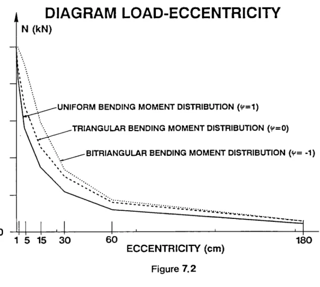
As shown in figure 7.2 by means of a diagram Ne, distribution
type (l) (ψ = 1, bitriangular distribution), is the most
favourable one, allowing highest eccentricity for a given axial load, or the highest axial load for a given eccentricity. The distribution type (3) (ψ = 1, uniform distribution) is the most unfavourable one, whereas the unsymetrical distribution (2) is most usually encountered.
To go in the same way as Standards for design in normal service conditions, the columns have been calculated here with the most unfavourable distribution of moments which is uniform, having a constant eccentricity and therefore a constant first order ben ding moment. A transformation method is proposed next for other distributions, allowing to reduce the unfavourable effect of the uniform one.
7.3.
Buckling lengths
The column buckling lengths considered in this project have been
chosen between 2.00 meters and 8.00 meters by steps of 2.00
meters. Therefore, pinended columns of 2.00, 4.00, 6.00 and
8.00 meters have been calculated, whereas a simple linear inter polation method is sufficient for any intermediate length.
7.4.
Design strength of steel
Any section considered in this program has a flange thickness equal or greater than 40 ran. This thickness is 40 ran for the HEM series, and varies between 40 and 125 ran for the HD series.
Eurocode 3 [19], which has to be used for the design in
normal service conditions, stipulates that the yield strength CJy should be reduced according to the thickness of steel. This
rule should be applied to Fe510, but steel FeE460 is not
directly mentioned in this Eurocode.
To simplify and to remain in the safe side, the decision has been taken to use in the calculations a yield strength reduced
as follows for steel Fe510, in accordance with EURONORM 25
[19]: Flange thickness [mm]
from
16
40
63
80
100
up
to
40
63
80
100
125
Œ
σγ
[N/ran2]345
335
325
315
305
The tensile stength has been taken everytime equal to 510
N/mm2.
For steel FeE460 the following characteristic values have been used, in accordance with [20] for flange thickness of 40
ran:
Oy = 450 N/ran2
CJt = 560 N/ran2
7.5.
Calculation with CEFICOSS in normal service conditions
In reality, however, it must be pointed out that the load given by ŒFICOSS is a little different from the load calculated according to Eurocode 3 [18] for, mainly, the strain harde-ning effect is considered in the stress-strain relationships included in ŒFICOSS. Of course, FIRST OF ALL, DESIGNERS HAVE TO COMPLY WITH THE STANDARDS FOR NORMAL SERVICE CONDITIONS. But for a quick and simple information, it was interesting to show together ultimate loads in normal service conditions and in fire.
From the other hand, some National Fire Codes accept clearly a load reduction in fire, and this concept will probably appear too in the final version of Eurocode 3. It is not logical indeed to consider for instance the full wind load on building together with a fire, or to have a crane in full action in an industrial building when fire occurs.
Therefore an interaction curve in fire has not to be directly compared with the interaction curve at ambient temperature where the values have been divided by 1.5. Such a comparison is not enough representative to qualify the economical interest for a construction system, and would not be sufficient for designers. It is necessary to give interaction curves in normal service conditions, as it has been made in this research.
Then, it has to be clearly noticed that results for normal ser-vice conditions given in this report are just furnished as information for scientific purpose.
7.6. Initial imperfection introduced in CEFICOSS
An initial column imperfection of the column has to be defined for CEFICOSS analysis, and has an influence for low bending moments. There is of course no specification in Standards to select this parameter, because a calculation in fire conditions is a quite new concept.
Eurocode 3 [18] defines a geometrical imperfection L/1000 to be applied with residual stresses in a second order analysis at ambient temperature. In another research [21] dealing with composite columns, the following initial imperfections have been adopted.
e0 = constant = L/500 for bending about the minor axis
To have a comparison with a few National Standards, several cal-culations have been carried out with CEFICOSS at ambient tempe-rature, without considering the strain hardening effect of steel
[7]. Some differences could be observed between the various standards and codes, and they are particularly significant for buckling about the minor axis. It appeared, however, that CEFI-COSS gives results which are in good concordance with the non-linear method of second order proposed in the German DIN 18800
[17], as well for bending about minor axis as for bending about major axis, when calculations are run with geometrical imperfections L/500 and L/1000.
In order to keep uniformity in the calculations made with CEFI-COSS it has been decided to adopt here too these geometrical imperfections defined in [21], in spite of the fact that residual stresses will also be considered. The results will be a little in the safe side, especially for bending about the minor axis.
The constant initial imperfections defined above have been sys-tematically introduced in the calculations in addition on the
indicated first order eccentricities.
7.7. Failure criterion
The fire resistance time of a structure can be based on diffe-rent criteria, usually depending on type of structure. For a column, failure corresponds practically to BÜCKLING. In the pro-gram CEFICOSS, the mathematical simulation of this physical behaviour is given by the Determinant of the Structure Stiffness Matrix, which being positive becomes negative (DSSM = 0); from a practical point of view, it is sufficient to analyse the Minimum Proper Value (MPV) of the matrix, which also goes to zero.
The behaviour of the column can also be observed through hori-zontal displacement and displacement speed of the mid-height node, which rapidly increase when buckling occurs.
'.8. Influence of residual stresses
To be able to evaluate the influence of residual stresses on the fire resistance, the program ŒFICOSS has been enlarged to accept a distribution of stresses in equilibrium inside of the cross section.
Using the distribution as well as the highest values suggested in Eurocode 3 [18], the stresses shown in figure 7.3 have been introduced in ŒFICOSS to simulate the tests n° 2 and n° 3 described in Appendix B, PART III, where:
°R(max) = ° ·3 °y = ° ·3 x 2 9·8 = 8·9 4 KN/01*2
The results of both simulations are given in figure 7.4. The observed differences are very small, particularly for test 2 when the column is buckling about the major axis (X = 0.3). For the column of test n° 3 having a slenderness ratio of about 0.8 the difference between the resistance times remain quite small
(1 minute, about 2 % ) .
It was also interesting to check the influence of residual stresses on the column of test 1 having the highest slenderness ratio for a low fire resistance time. The supposed residual stresses distribution is given in figure 7.3, with a maximum of 0.3x36.4 = 10.92 kN/cm2. The table of figure 7.4 shows that the
calculated fire resistance time decreases down to 35 minutes (~ 5 %) in this case.
Of course, actual residual stresses in the beam have not been measured, but these simulations show that their influence is probably quite small for thick flanged columns in the domain considered in this research. As this influence consists in a small reduction of the fire resistance time, and in order to have conservative results, it has been decided to perform the calculations by taking into account residual stresses as pro-posed in Eurocode 3 [18] and explained on figure 7.5. The stresses will be kept constant on the whole flange or web thick-ness (as made in figure 7.3) and will be combined with the ini-tial geometrical imperfection defined earlier in § 7.6 and given in figure 7.5.
8. DIAGRAMS
8.1. Calculation process
For any column cross section the calculation of températures in
different patches of the discretized section is subordinated
neither to the column length nor to the loading. Therefore the thermal analysis can be done first and the resulting time depen dent temperatures can be used as data for every static calcula tion dealing with the same cross section.
The statical calculation process is described in figure 8.1;
the first step is to find by iterations the ultimate axial load at ambient temperature (point A on vertical axis corresponding to a time t=0' ). Then ŒFICOSS is run by reducing progressively
the load for a series of eccentricities. For instance a load
corresponding to the point Β applied with an eccentricity of 15
cm gives a fire resistance time tB 15, and defines the
point C in figure 8.1.
All the curves established with various eccentricities permit to read by interpolation the axial loads Ν for the required fire resistance times 30 and 60 minutes as shown on figure 8.1, and to create a file including pairs of values Ne for each fire resistance class.
In reality whole curves established with about 20 points as
given in figure 8.1 are not necessary; it is sufficient to find
points near the classified fire resistance times to allow a
quite accurate interpolation. An average of not less than 3
simulations are needed, however, for each requested point.
For a practical purpose, constant relative eccentricities have been chosen: ratios e/h = 0, 0.10, 0.25, 0.50, 1.00, 2.00 and 4.00 have been used for bending about major axis, while ratios e/b = 0, 0.10, 0.25, 0.50 and 1.00 have been used for bending about minor axis, h and b are of course the height and the width of the steel shape.
As the number of parameters is not too high, both tables or dia grams can be convenient for designers, and both forms are pre sented for the examples given in PART II of this report.
Tables are, however, the main data base which allows to build up the diagrams by means of any spreadsheet software with integra ted graphic possibilities.
8.3. Interpolation on the buckling length
The simple linear interpolation method is proposed to evaluate
the ultimate load corresponding to a buckling length between
those given in the tables.
The examples of figure 8.2 show that by performing a calculation in CEFICOSS with the interpolated load for 5.00 m, a fire resis tance time of 30 minutes is practically found in both examples. Moreover, if more accuracy was needed, the users have a possibi
lity to improve the interpolation, for four buckling lengths are given in tables allowing to see the look of the curve, as shown in figure 8.3
8.4. Transformation method for non uniform moment distribution
As noted before, calculation have been performed with an uniform first order bending moment (ψ = 1.00 according to figure 7.1).
At ambient temperature, Eurocode 3 [18] proposes to apply a
corrective factor β on the moment in the interaction formula, β depending only on the form of the moment distribution.
Figure 8.4 shows a column HD260x260x329 calculated for vairous lengths and eccentricities, as well as for bending about both axes and for an uniform or a bitriangular bending moment dis tribution.
In the first of the three last columns of the table, the method
proposed in Eurocode 3 has been applied as defined in figure
8.5, and leads sometimes to unsafety when eccentricity increa ses.
The βψ method used in the two last columns of the table has
been established in another research [21] using CEFICOSS to
calculate steelconcrete composite columns. In this method β is not only a function of the form of the moment distribution, but also of the slenderness ratio and of the relative eccentricity e/h (or e/b). Except for the calcul of β, this method is simular to the method of Eurocode 3, presented in figure 8.5.
The differences observed in these two last columns. come from two possible ways to apply the method. In the penultimate column,
^bitr h a s been calculated exactly as in figure 8.5 only
from the uniform value Nu, what means:
K
u -andN b i t r =
Nc _ !
Nu e NcNc
1 + ß.Ku.e 1 β (Nc/Nu 1)In the last column, however, an equivalent eccentricity has been
calculated: ee = ß.e and N¿¿t r has been found by interpo
lation with this equivalent eccentricity in the table given in PART II for this section and for an uniform distribution.
The differences observed between the two possible ways to apply the βψ method are quite small, and depend only on the more or less good applicability of the basis formula presented first in figure 8.5.
It can be observed, however, that the values found in these last columns of figure 8.4 with this βψ method are more conservative that the other ones. This method could be used rather than the method of Eurocode 3.
9.
CONCLUSIONS
This research will finally allow to use steel elements more eco-nomically. Moreover the validity of the program ŒFICOSS has been improved to simulate whole structures including as well steel-concrete composite elements as pure steel elements
([22], [23], [24]).
In a next step, to improve the convenience of the results, it should perhaps be envisaged to put them on a floppy disk with a simple program allowing on a personal computer quick interpola-tions as well as the transformation of the bending moment dis-tribution.
Moreover, the results of this research can be used as a basis to establish a simplified method or to improve some existing methods. For instance it can be observed in tables given in PART
II that it is difficult to define exactly when the massi vit y could be sufficient to reach automatically the fire resistance class F30 with a correct design in normal service conditions. As a matter of fact, that occurs for F30 when:
N(F0,EC3)
% 3 0 ^ = maximum service load with safety 1,5 factor equal to 1,5
It can be observed in the tables that it depends not only on the flange thickness or on the section factor U/A, but also on the slenderness ratio of the column, and, moreover, on the eccentricity.
To simplify as far as possible, only the flange thickness and the slenderness ratio could be considered, with the minimum ratio N/N(F0,EC3) of any eccentricity. Moreover, the given ratios N/N(F0,EC3) could be multiplied by 1,5 to have a direct comparison with the maximum service load calculated according to EC3. This process leads directly to the diagrams of figures 8.7 and 8.8 which are very easy to use and to interpretate, showing clearly what should be the reduction of load in the worst case for the fire classes F30 and F60.
10. BIBLIOGRAPHY
[1] SCHLEICH J.B./ REFAOCAFIR, Computer Assisted Analysis of the
Fire Resistance of Steel and Composite ConcreteSteel Struc
tures. C.E.C. Research 7210SA/502, Final Report EUR 10828 EN, Luxembourg 1987.
[2] CTICM, essai n° 86 U 052 du 22.04.1986, Essai de résis
tance au feu d'un poteau en profil HE 500 AA en acier doux, rem pli de béton armé.
Station d'Essais au Feu du CTICM à MaizièreslesMetz. [3] FIRTO Technical Evaluation TE 6143
Fire resistance test in accordance with B.S. 476: Part 21 on a composite steel and reinforced concrete column (305 mm χ 305 mm) Borehamwood, January 1988.
[4] FIRTO Technical Evaluation TE 6144
Fire resistance test in accordance with B.S. 476: Part 21 on a composite steel and reinforced concrete column (356 mm χ 368 mm) Borehamwood, January 1988.
[5] ECCSTechnical Committee 3 Fire Safety of Steel Structures European Recommendations for the Fire Safety of Steel Struc tures. Elsevier Science Publishers B.V., Amsterdam 1983.
[6] Convention C.C.E. n° 7210SA/505; Outils pratiques de dimension nement pour poutrellescolonnes en acier non protégé soumises à l'incendie. Rapport technique n° 1 (RT 1) March 1987.
[7] ARBEDResearch Centre; Practical design tools for unprotected
steel columns submitted to ISOfire. C.E.C. Agreement n°
7210SA/505, Technical Report n° 2, Luxembourg, October 1987.
[8] ARBEDResearch Centre; Practical design tools for unprotected
steel columns submitted to ISOfire. C.E.C. Agreement n°
7210SA/505, Technical Report n° 3, Luxembourg, March 1988.
[11] Fire resistance tests Elements of building construction; International Standard ISO 834, first edition, 1975.
[12] FRANSSEN J.M.; Etude du comportement au feu des structures
mixtes acierbéton. Thèse de Doctorat. Université de Liège,
Février 1987.
[13] HUBERT Α., SCHAUMÄNN P.: Tenperaturabhängige Werkstof feigen
schaft en von Baustahl bei Brandbeanspruchung. Der Stahlbau 54, Heft 3, S. 8186, 1985.
[14] HUBERT Α. : Experimentelle Untersuchungen zum Brandverhalten kom
pletter, ebener Rahmensysteme aus Baustahl, Forschungsbericht
• zur Teilaktivität 3.2 des Vorhabens Bau 6004/P86, Studiengesell schaft für Anwendungstechnik von Eisen und Stahl e.V., Düssel dorf, durchgeführt im KRUPP Forschungsinstitut Essen, 1984 (Teil 1 und Teil 2).
[15] Amtliche Materialprüf anstalt für das Bauwesen Institut für
Baustoffe, Massivbau und Brandschutz Technische Universität Braunschweig: Untersuchungsbericht Nr 1618/8510 vom 04.12.1988. [16] Laboratorium voor Aanwending der Brandstoffen en Warmteover
dracht Rijkuniversiteit Gent. Rapports d'essais N °s 5871,
5872, 5873 et 5874.
[17] DIN 18800 Teil 2; Stahlbauten: Stabilitätsfälle, Knicken von
Stäben und Stabwerken. Deutsche Norm. Entwurf Dezember 1980.
[18] C.E.C.; Industrial processes Building and Civil Engineering
EUROCODE N° 3: common unified rules for steel structures. EUR 8849, Bruxelles Luxembourg 1984.
[19] EURONORM 2572: Aciers de construction d'usage général. Novem bre 1972.
[20] ARBED StE 460 FRITENAR: Hochfester Feinkornbaustahl für Pro file. Luxembourg, February 1989.
[21] ARBEDResearch Centre; Practical design tools for composite
steelconcrete construction elements, submitted to ISOfire,
considering the interaction between axial load Ν and bending
moment M. C.E.C. Research 7210SA/504, Final Report, Luxembourg, August 1989.
[22] SCHLEICH J.B.; Numerische Simulation - Zukunftsorientierte Vor-gehensweise zur Feuersicherheitsbeurteilung von Stahlbauten. Der Maschinenschaden 60 (1987) Heft 4. Allianz Versicherungs AG, München.
[23] SCHLEICH J.B.; Numerical simulations/ the forthcoming approach in fire engineering design of steel structures. Revue Technique n° 2 1987.
[24] SCHLEICH J.B.; "Global Behaviour of Steel Structures in Fire." Building in Steel - International Symposium in Stratford-upon-Avon, September 1989.