689
17th INTERNATIONAL SHIP AND OFFSHORE STRUCTURES CONGRESS 16-21 AUGUST 2009 SEOUL, KOREA VOLUME 1 COMMITTEE IV.2
DESIGN METHODS
COMMITTEE MANDATEConcern for the synthesis of the overall design process for marine structures, and its integration with production, maintenance and repair. Particular attention shall be given to the roles and requirements of computer-based design and production, and to the utilization of information technology.
COMMITTEE MEMBERS Chairman: D. Karr D. rennan R. Bronsart J. hambers C. P. Chen I. Chirica J. McGregor F. Oneto P. Rigo Y. Takaoka M. Ventura J. S. Yum KEYWORDS
Cost Modelling, Data Management, Design Tools, Fire Simulation, Hull Monitoring and Maintenance, Optimisation, Information Technology, Product Data Modelling.
CONTENTS
1. INTRODUCTION ... 693
2. DESIGN AND PRODUCTION PROCESSES ... 695
2.1 The Design Process ... 696
2.2 Bridging the Gap: SPM Systems and Lifecycle Management Tools .... 696
2.3 Hullforms ... 697
2.4 Structures... 698
2.5 Novel Techniques ... 699
2.6 The Production Process ... 699
3. INFORMATION TECHNOLOGY ... 701
3.1 Product Data Model Advancements ... 701
3.1.1 Computer Aided Approval ... 702
3.1.2 Integration ... 704
3.1.3 Management of Design Changes... 706
3.1.4 Project Management Applications ... 707
3.1.5 Replication and Sharing ... 710
3.2 Product Model Data Quality ... 712
3.2.1 Quality Control for Ship Structures Data Models ... 714
3.3 Rules and Rule Engines ... 715
3.3.1 A Rule Engine for Quality Criteria Checking ... 717
4. MAINTENANCE AND REPAIR ... 718
4.1 Hull Condition Monitoring ... 719
4.2 Reliability Based Inspection and Maintenance ... 720
4.3 Performance Standards for Protective Coatings ... 721
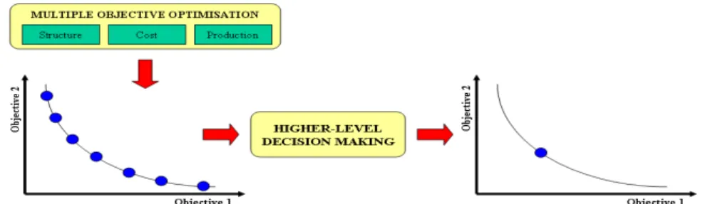
5. MULTI-CRITERIA AND MULTI-STAKEHOLDER OPTIMISATION... 723
5.1 The IMPROVE Project ... 724
5.2 Multi-Criteria Decision Making ... 725
5.3 Meta-Modelling of Criteria Functions and Subspaces ... 727
5.4 Engineering Design as a Decision-Making Process ... 729
5.5 Multi-Stakeholder Design: Theoretical Background ... 730
5.6 Fundamental Design Support Systems ... 731
5.7 Enhancement for Multidisciplinary Links in Synthesis Models ... 732
6. RECENT DESIGN TOOL DEVELOPMENTS ... 757
6.1 CAD/CAE Systems... 739
6.2 Design Tools for Production and Cost ... 741
6.3 Design Considerations for Fire and Smoke ... 743
6.3.1 Zone Models ... 744
6.3.2 New Functionalities ... 764
6.3.4 Summary ... 767 7. CONCLUSIONS ... 748 REFERENCES ... 750
1. INTRODUCTION
Marine systems design synthesizes many technologies from a wide range of disciplines. Complicated demands from many aspects must be considered during the design process. Throughout the ship design process, a representation of the ship including its structure and all components is developed and stored in ship product data models within a data management system. Following the subsequent steps in the process chain, this product data model is handed on, modified, and added to by many partners. At different stages, data is derived and transformed into multiple representations which have to be kept consistent. Every step of the design process is controlled by rules, standards and regulations which have to be observed. Disregarding these rules results in the deterioration of the product data quality with the necessity to allocate a considerable amount of resources and therefore costs for engineering change management and correction activities.
Increasing international competitive pressures are motivating all industrial corporations to continually reduce cycle time, improve return on assets and reduce working capital. In addition to improving internal production efficiency efforts, corporations are turning to external factors such as subcontractors and suppliers to achieve new cost savings and higher profit margins. Ship construction and repair are assembly-intensive operations that involve high levels of logistics; supplier parts and materials can account for 70 or more percent of the total production costs. Re-engineering shipyard-supplier business processes can help shipyards to optimise processes and products. Overall material management and production strategies can be re-engineered and streamlined to make optimum use of in-house skills and out-sourcing resources. Thus, integrated supply chains are a key opportunity for gaining new competitive advantages and markedly improving overall production costs.
Shipbuilders face a number of strategic pressures to deliver ships in a shorter timescale, of increasing complexity and modularity, with demanding environmental rules, whilst lowering initial build and operating costs. One strategy for achieving these objectives is to keep partners more closely linked throughout the supply chain. Partnerships between customers, shipyards and sub-contractors are a common feature of naval shipbuilding and are now an emerging theme in the commercial market. The complexities of the information exchange between shipyards and sub-contractors, and the need for defined and effective workflows, including an effective engineering change management process, are crucial. The range of information to be managed includes CAD documents, manufacturing instructions, work packages, operating manuals and in-service support considerations, the creation and management of differing configurations of this information, and the compliance tracking with customer requirements.
Future ship design and production is expected to utilize an integrated set of software tools which will ultimately extend to the management of the vessel throughout its entire life cycle. A product model approach (PMA) is evolving and being developed, advocated and used throughout the industry, and it seems reasonable to expect that future vessels will be designed and built using a PMA philosophy. The first building block in this process is the generation of a central database, which will include material properties, structural component geometry, and relationships between elements. This geometric database will play a central role in future shipbuilding and marine structural design and construction processes.
Collectively many tools provide the ability to determine loads for specific operations; model and track corrosion, fatigue and collision damage and repair, produce structural analysis models for fatigue and strength assessment, and present results to the analyst to help assess risk and the most efficient maintenance actions. These tools are discussed in the framework of the design and production process in Chapter 2.
The design and construction of commercial ships and marine structures in general are characterized by small series or one-of-a-kind products which results in highly fluctuating workloads and strong competition in terms of price. Product performance and time to market requirements make it a unique engineering discipline. In order to realize new ship buildings according to the given contract specifications, dynamically changing and globally spread intra- and inter-organizational collaboration networks need to be set up and to be managed continuously. Relevance in this regard is given by the fact that depending on the ship type and shipyard business strategy, 70% or more of the shipyard’s value creation is based on purchased services and equipment (Bronsart et
al. , 2006).
In the scope of this report, the term “Information Technology” (IT) is used for methods and systems to support the exchange of product and process model data in the overall design and production process. Tools to perform specific tasks are interfaced with the help of IT methods and systems either in-house or between partners (companies) involved in the numerous ship design and production process phases. At the same time, ship owners and operators are becoming more demanding in terms of cycle time from contract to delivery, which results in shipyards becoming more reliant on a network of design subcontractors. The subcontractors are often geographically dispersed, which creates challenges in developing a fully integrated product model to support the vessel construction. Issues and challenges that are faced and to be solved in such a distributed design environment are identified and alternative approaches are described in Chapter 3. Design for better maintenance and fewer, less costly repairs is one of the critical issues for designers. One of the responsibilities of design is to foresee the particular critical areas prone to failure in operation conditions, and to avoid such failures by appropriate design solutions at various design stages. These measures, addressed in Chapter 4, will reduce the cost of maintenance and repair during the life cycle of marine structures. Life cycle costs can be reduced by various design strategies such as the adoption of
standardized structural parts, standardized module packages including prefabricated passenger and crew cabins, prefabricated pipe packages, and other integrated units. Using standardized modules not only benefits the owners owing to better reliability, less weight and space savings, but also holds advantages for shipyards by reducing design and production costs.
Optimisation is playing an increasingly important role in the design procedure for ships and offshore structures. The multi-stakeholder approach is a novel methodology for system’s design involving a limited number of institutional users, producers, operators, controllers, and it is conveniently named Multi-Stakeholder Design. This is indeed typically the case for a ship design, where shipyards and ship owners need to jointly accept the final design alternatives. Major risks in the successful full-scale development of complex engineering systems arise from the challenges of effectively addressing the competing needs of improving performance, reducing costs, and enhancing safety. Strategies and approaches for optimisation of marine structures is the topic of Chapter 5. Recent advances in design tools are addressed in Chapter 6. Of particular emphasis is the discussion of advancements in fire and smoke considerations. Fire science today, with new powerful and affordable computers, has access to an vast field of numerical simulations of fire and smoke. The fire is no more a standard temperature curve but can now be estimated with simulation capabilities for innumerable scenarios. This is mainly due to the tremendous work of national standards codes on fire safety and the work of fire laboratories for the last decades across the world. Many fire phenomena have now the possibility to be simulated in a validated manner with standard methods of testing for validation.
2. DESIGN AND PRODUCTION PROCESSES
Over the past decade, the ship building industry has begun to develop and apply Single Product Models (SPM) for improving the management and efficiency of design, analysis and production of commercial and naval vessels. SPMs are extensive single 3D CAD data models incorporating hull structure, propulsion, steering, piping, electrical, HVAC and other systems, which make up a complete ship. Ship classification societies and navies (most notably the USN in their DDX project) have ongoing R&D efforts to bring this technology to its full potential. This work involves leading software providers, including Tribon, Intergraph, Catia and ShipConstructor who are developing products, training and documentation to facilitate the use of SPMs by ship builders and design authorities. It is reasonable to expect that future vessels will be designed and built using SPMs.
There is strong interest by ship owners and agencies (including navies and ship classification societies) and the SPM software producers to extend the SPM applications beyond design and production to the lifecycle management of ships and offshore structures. This offers significant potential savings in operation and
maintenance costs as well as improved understanding and confidence in marine safety. 2.1 The Design Process
The tools and techniques used to design ship structures have evolved over the last forty years from producing blueprints on the drafting board to the digital design of today. As computer technology became more powerful and relatively less expensive, computer-aided-design (CAD) systems evolved to support the design of complex products. CAD and other related tools empower designers and engineers to create innovative products more quickly and efficiently.
During the 1990’s, the single product data management systems continued to expand in scope and scales. Companies recognized that they could use these systems not just to design their products, but also to manage the product data over the entire lifecycle from concept through deployment. At the same time, CAD and computer aided engineering (CAE) technologies grew in complexity and capabilities.
Less expensive hardware and more powerful tools provided the incentive for many companies to move from 2D CAD to 3D, the prerequisite for many analysis techniques like the finite element method (FEM). Once limited to mainframe computers, these powerful analysis tools also moved to the desktop, putting the full range of CAE at the engineer’s fingertips.
2.2 Bridging the Gap: SPM Systems and Lifecycle Management Tools
Developing links between SPM databases and analysis tools used in the design process will undoubtedly reduce the effort currently required to perform assessments of marine structures. However, in order to develop this link, issues related to CAD interoperability, or the ability to share a CAD model across different applications, must be addressed.
Hidden errors and anomalies in the originating CAD data representation, as well as translation issues, often result in numerous problems and frustrations for the downstream users. While the emergence of standards such as STEP has helped reduce some of these problems, true interoperability is still far from reality. Some of the issues that affect data exchange from one CAD system to another are:
z Model quality in the originating CAD system: Many times the original
model itself is of poor quality. Common problems include missing parts, invalid definition, and lack of connectivity (poor connection definition with neighbouring structure). These problems could be due to user error, numerical limitation of the CAD system, and/or design requirements. Many CAD models work well for design and drafting, but they do not have the quality required for structural finite element meshing operations.
primary objectives. This leads to differences in the way a data type is interpreted by each package. Thus, when a model is moved from one system to another, inaccuracies can be introduced due to mismatches or poor communication.
z Differences in tolerances: Geometric data is often in parametric form,
accurate to the order of the specified tolerance. Differences in tolerance introduce gaps and overlaps in the model that can lead to problems when attempting to generate finite element meshes.
z Limitations of translation: Inaccuracies are introduced by translation errors.
Often all the data types of a CAD system do not have a one-to-one mapping with the standard formats used by translators, so approximations need to be made. Approximations are also applied when converting data from the standard translator to the format used by the receiving system.
While fixing problems at the source (i.e.: within the original CAD representation) yields the best results, it is not always possible to do so. Finite element analysts usually do not have control over how a model is first created, so they are forced to deal with problematic CAD files. As a result, tools must be available to make repairs to imperfect CAD models. Common types of repair operations include:
Healing: Healing is designed to automatically detect and repair geometric and topological inaccuracies in the imported model by performing the following operations: (1) simplifying data by converting spline surfaces to analytic surfaces (i.e.: cylinders or spheres) wherever possible; (2) correcting topological problems by stitching; and (3) bridging gaps between boundary curves and surface data by re-computing intersections after extending the surfaces. Healing should also support the automatic detection and removal of sliver faces and short edges during import.
Tolerance modeling: Tolerance modeling addresses problems associated with inaccurate data or “leaky” models (with poor connectivity between neighbouring elements, such as surfaces) and provides the framework for model healing and data translation. Since poor connectivity may be an issue when a small tolerance is used, this tool increases the tolerance in problem areas, generating less precise, yet connected geometric elements. The less precise geometry can then be used to create valid topologies for mesh generation. Tolerance modeling does not assume (or require) that the geometry agrees with the topology, and takes the geometric error in the topology into consideration during modeling operations and calculations.
2.3 Hullforms
A recent review of the literature demonstrates significant interest in advancing the integration of CAD data into the ship design process. Roh (2007, 2008) published a pair of studies which looked at improving ship design practices using a 3D CAD model of a hull structure. As Roh suggests, often (during the initial stage of ship design) a 3D CAD model of the hull structure is not generated because of effort involved.
Unfortunately, in the absence of this model, a designer must manually calculate the production material information of a building block by using 2D drawing and parent ship data at the initial planning and scheduling stages. In order to reduce the level of effort required to produce this data, Roh has developed a methodology and supporting tools which allow users to easily generate the hull structural model at the initial design stage. The applicability of the proposed method was demonstrated by applying them to a deadweight 300,000 ton VLCC.
Lu (2005) presented a study which focused on the application of a single NURBS (Non-uniform Rational B-Spline) surface for the purposes of representing a sea-going ship hull. Several typical full-scale ships' hulls were modelled using this technique. In a series of papers which also looked at the application of B-spline surfaces in ship hull design, Pereza and Suarez (2006, 2007) presented an approach designed to create developable NURBS surfaces. Developable surfaces can be formed from flat sheets without stretching or tearing and with a minimum use of heat treatments, so the forces required to form sheet materials into developable surfaces are much less than for other surfaces and the construction costs are lower. Tauseef and Ding (2006) also examined the application of NURBS. In their paper, they describe a hull fairing process based on the use of a NURBS ruled surface method (Cross-Fix Method).
2.4 Structures
Jang et al. (2008) describe an algorithm capable of generating a finite element representation of a ship structure using a 3D CAD model as the primary source of geometric data. The algorithm is based on what the authors describe a Hold Analysis Integrated System (HAIN System) and a Whole Ship Analysis Integrated System (WAIN System).
The HAIN System includes:
z Interface with CADRA/GS-CAD z Automatic FE modeling for cargo hold z Automatic load generation module z FE model and load check module z Automatic reporting system
The WAIN System includes:
z Interface with GS-CAD z Seakeeping analysis
z Design wave decision module
z Automatic FE modeling for whole ship
z Load generation module from seakeeping results z FE model and load check system
The basic concept of their approach is to decompose surfaces using stiffener lines into sub regions and generate the finite element mesh using rules based on accepted finite element modeling practices.
2.5 Novel Techniques
In a paper published by Tann and Shaw (2007), a web-based object oriented design support system is described. The main objective of this approach is to speed up design and production times. In terms of parametric design, if a problem arises and, according to the authors does not exhibit complex spatial requirements, there could be a possible solution template that can be altered to address the specific designs. If this could be developed into a system it could save a significant amount of time. The authors provide examples that have reduced costs for companies around the world.
Schachter (2006) published a paper describing a design process approach named “solution focus design”. According to the author, this method was first created in a context where the decision of what concept to be adopted supersedes the use of the classical design spiral, suggesting a combination of the spiral with morphological charts. The advantages are in terms of allowing for the introduction of creative ideas into the conceptual design process, eventually leading to an innovative product or design solution.
Woods (2006) investigated the “power of ambiguity” and its use in conceptual design. According to the author, there is a common link between the coefficients and ratios used in technological design (Naval Architecture) and conceptual sketches used in the artistic design of vessels. Both sets of attributes can act as pre cursors to design, each do so in entirely different ways.
Birk (2007) reported on the continuous development of an automated optimization procedure for the design of offshore structure hulls. The paper summarizes the new developments in the shape generation, illustrates the optimization procedure and presents results of the multi-objective hull shape optimization.
2.6 The Production Process
Roh and Lee (2007) describe a methodology for generating production material information using a 3D CAD model. According to the authors, a 3D CAD model for a whole hull structure is generated first, and the block division method for dividing the 3D CAD model into a number of building blocks is then developed using the relationship between the hull structural parts. In order to evaluate the proposed methodology, the authors applied the technique to a 300 000-ton very large crude oil carrier.
Hsu and Wu (2006) published a study on production-oriented design for the Capsize bulk carrier. This article was largely focused on the reduction of man-hours and steel
in ship construction. The reduction of steel and man-hours was addressed by replacing the longitudinal reinforced pipe duct (LRPD) with a transverse reinforced pipe duct (TRPD). By doing this it is suggested that the number of steel pieces is reduced, and as a result, the man-hours required is also reduced. The TRPD are able to reduce the number of steel pieces because, “it has a thicker (outer) bottom, inner bottom, and girder plates, its rigidity is greater than the LRPD”. The article steps the reader through equations that relate girder depth and deflection due to shear. It shows that the greater the depth the less resulting deflection due to shear. With the TRPD having a thicker plate than the LRPD, the TRPD will have less deflection.
The use of TRPD was tested by using ABS’s SafeHull software tool. The most critical load and boundary conditions were applied to a triple hold model using both types of ducts. The analysis was then completed and showed that the TRPD had less deflection and exhibited less von-Mises stresses than a model with LRPD. The reduction in steel weight is not as significant as the reduction in steel pieces thusly saving man-hours. Okumoto et al. (2006) published a paper dealing with simulation-based ship production using 3D CAD data. The article is largely focused on the use of three-dimensional CAD to improve production by simulating preconstruction, speeding up data modification time, and erection planning. By simulating the preconstruction, the construction becomes more effective and the completion of a project much less to do with trial and error. By being more effective in the construction, the material costs also can be reduced. In addition, the modification time can be reduced, saving time and money, by updating the modifications via the 3D CAD program. It is also stated that there is a reduction in lead time since materials can by calculated and order electronically and the skilled labour can be replaced by automation.
The article also states that with regards to ship production, simulations may be applied as follows:
z Analysis and evaluation of the production process z Planning and assisting with production
z Training workers in such skills as line heating, welding, and straightening z To confirm the safety of work operations
The use of CAD in construction can also largely assist installation abilities. The example of the use of scaffolding and mechanical lifting devices are aided by 3D CAD since the scaffolding can be planned before hand and the problems that arise during scaffolding construction can be avoided. In short, 3D CAD allows for planning at all stages to improve quality, safety and money (Yasuhisa, et al., 2006).
In a recent papers by Huang et. al. (2007, 2008), a description of a methodology focused on the problem of buckling distortion is provided. For the purposes of this study, buckling distortion is due to butt welding thin steel pieces together. This welding causes compressive stresses in the steel and since the thin steel does not have the
strength to resist these residual stresses it buckles. In order to prevent distortion, the authors suggest the use of transient thermal tensioning (TTT). As the stiffeners are being welded, two heaters travel along the plate with the welded in the zones where compressive residual stresses are induced. The heat causes tension in these zones counteracting the compression. The intensity of the heat and the speed of the heaters vary with the thickness of the steel. In one test involving simple 5mm thick panel the TTT was found to totally eliminate the buckling but was not able to eliminate bowing in the steel plate. In another test with 10mm complex welding, the TTT decreased the buckling by 50%. This test also included small 3mm precision fillet welds.
Reverse arching is also a way of reducing residual stress. By applying a bending action to the beam and plate the compressive residual stresses are countered by tension and once welded the bending is eliminated. This was found to reduce the one third of the original stress and increasing the buckling strength.
3. INFORMATION TECHNOLOGY
In the previous ISSC 2006 report, the committee documented the underlying principles of collaboration and communication procedures implemented in a variety of software systems to be used in distributed but concurrently working ship design and production network scenarios. Special emphasis was put on overall requirements and the role of standardization of product model data.
In the recent years it has been noted a slowing down on the development of the standard ship Product Data Model from STEP (ISO 10303) although a new AP233 Systems Engineering Data Representation is under development and currently in draft status. This Application Protocol shares some modules with the AP239 devoted to Product Life Cycle Support (PLCS) that was published on 2005.
3.1 Product Data Model Advancements
Although with a slower development of the ship Product Data Model, STEP based technologies are being used for other applications such as the management of ship repair data (Ventura and Guedes Soares, 2007). In the scope of the US National Shipbuilding Research Program (NSRP) the Integrated Shipbuilding Environment (ISE) Project has developed standards and tools and have demonstrated their capability for successful product data exchange (structures, piping, HVAC) during the design stage (Gischner et al. , 2006).
Non-standard data models continue to be developed to support production (Oetter and Cahill 2006), production planning and scheduling, virtual assembly (Wu et al. , 2007) and life-cycle maintenance, namely hull maintenance (Jaramillo and Cabos, 2006; Renard and Weiss, 2006; Cabos et al. , 2008) using mainly XML based technologies.
The product data models are being extended to take into consideration lifecycle data (Briggs, 2006; Kassel and David, 2007). Beadling (2008) proposes the adoption of Product Lifecycle Management (PLM) application software developed specifically for ship design and production that can be used in concert with solutions for collaboration, digital mockup and product data management developed for aerospace to bring about business transformation across all phases of a single ship or a class of ship’s lifecycle. Kassel and Briggs (2008) consider an alternate approach to the exchange of ship product model data based on general-purpose STEP application protocols. The objective is to provide the functionality defined in the shipbuilding application protocols using a combination of STEP AP239, AP214, and reference data libraries. It is expected that AP239 translators will soon be available, thus enabling the exchange of significant portions of ship product model data. Bentin et al. (2008) presented a product model that supports assembly, room and system views, using CAD data and Product Data Management (PDM) in order to enable the digital factory concept. DNV has presented a product model specifying a standardized vessel description for class work (Vindøy, 2008). The development of fast prototyping systems allows the designer to take full advantage of a product data model (Don et al., 2007).
Dalhaug and Hardt (2006) discuss the risks of handling digital information as a fundamental part of the communication base. If the vision is to develop a paperless and digital organisation, the challenge is to move from a paper based to a digital work environment in a controlled manner. A Public Key Infrastructure (PKI) is described as an enabler and a support to the vision by ensuring that the security of a paperless production environment is equivalent or better when compared with a paper based production. The issue of PKI relates to how electronic documents are secured in storage (short/long term) as well as in transit, to avoid breeches in confidentiality, integrity, traceability and availability, and how non-internal users of graded information can be authenticated in a secure manner. The results from a substantial feasibility study and an outline of the design of the technical solution and the suggested infrastructure are presented.
Renard (2007) describes the basic ideas to develop methods and tools dedicated to European cooperative naval (military) projects. The research project CADET and its software tools in particular shall support all decision steps recognized as contributing to the success of any naval cooperative project. They provide a common methodology, a common language as well as the same structure of information for all partners (navies and shipbuilders). Partners will be provided with a complete road map of the project, from initial navies requirements to final building in the shipyards. CADET tools are intended to support all decision steps which have been recognized as contributing to the success of a naval cooperative project.
3.1.1 Computer Aided Approval
and opportunities. They define computer aided approval as a synonym for the review and approval of design and construction on the basis of digital documents and data model files. The ship design approval process today is to a large extent dependent on the checking against predefined rule sets, which leads to a higher efficiency compared to direct calculations procedures. Computer aided approval is designed to combine the flexibility of the simulation based approach with the efficiency of the rule based way of work. The needs, problems and opportunities when implementing the new approach by using ship product data from ship yards and supplier are described.
Eberwien et al. (2007) describe the implemented CAA process in more detail. During the approval process, digital documents and optionally associated data model files representing the ship structure or machinery systems or parts thereof need to be exchanged between the customer (shipyard, design agent, marine systems supplier) and the classification society. All documents supplied to the classification society have to be of a legal character. The class on the other hand has to check and subsequently approve the provided documents in an auditable manner and returns an approval document which again is compliant with all relevant legal requirements. Data model files, additionally provided by the customer, may be used by the class for supplemental information.
In order to guarantee consistency in the information exchange activities, all documents have to conform to a predefined standard. For this purpose, Germanischer Lloyd (GL) uses signed PDF container which is a standard PDF file containing attachments. While the digital documents technically make up the cover page of such a container file, the data model files are provided as attachments to the container. To turn the PDF container into an information source legally binding, it is digitally signed. By the digital signature the submitting customer takes over the responsibility for the consistency of the digital document and the data model data files within the signed PDF container. To support customers using this standard for information exchange, GL offers two scenarios for the creation of a digitally signed PDF container. Provided the customer has means to create PDF files from his CAD data and to fill a PDF container, he may submit a digitally signed PDF container directly to the web portal of GL. In the alternative scenario, a customer may use a web application which supports the creation of a PDF container. The process is guided in a way that all documents and data model files attached to the container by this service are accompanied by an appropriate label, i.e. the sequence of pages within the digital document conforms to the standard. All pages are automatically bookmarked and named after the given labels. The web application service accepts PDF and DXF for forming the digital document body of the PDF container. All other formats are treated as attachments to the container. The PDF container created by the GL web application service is returned to the customer, the signature of the PDF container turns it into a legal document. This can only be done by the customer; therefore all services provided only support the physical creation of the PDF container.
At GL, the signed PDF container is fed into the fully digital based approval processes which consists of document registration and permanent storage, revisions by plan approval engineers and finally plan approval. The PDF container is annotated, marked and redlined by the plan approval engineer just as he/she would do on a paper based document. The result can be viewed by e.g. the free Acrobat Reader or other PDF viewing software. The customers have access to the annotations without the need of an extra software licence. Looking over the annotations of a PDF document is much more convenient than to examine them on a paper based document. All digital annotations of a PDF document are displayed by the PDF viewer within a separate navigation pane. The list of annotations not only serves as an overview but is also directly linked to markups or redlining objects within the digital document. Thus checking the remarks made by the classification society reduces to tabbing through a list and executing a display function for the annotation of interest.
Class approval processes in shipbuilding introduce additional and specific requirements for information management systems to be used in the ship design process. Ehrler et al. (2007) describe that currently these requirements are not sufficiently addressed by state of the art PDM/PLM software tools and solutions. Classification societies have to manage product oriented structures (as designed, as built), associated analysis and simulation data (FEM, CFD) and manifold relationships to external part catalogues and material databases. Additionally, the underlying information model has to be extensible and adaptable during production use in order to satisfy short term requirements from different certification projects.
In this context a "Technical Information System" (TIS) project at Germanischer Lloyd, based on PDTec's ice.NET platform is implemented. TIS integrates data models from various legacy systems and provides configurable XML and web service interfaces to associated simulation programs. In addition to the information model and system architecture developed it is presented how to provide functional prototypes within a short time frame and limited budget which enables process-specific organization of information in a networked, project oriented structures including access control mechanisms, tracking and audit support. On the basis of a project example the requirements driven extension of the data model with the UML based development tool ice.NET Studio is shown.
3.1.2 Integration
The challenges for integrating well proven, existing software with new programming paradigms in the context of a specific tool to simulate a new ship design e.g. in a bridge simulator is described by Abels (2007). To achieve this, a system kernel in Java application is combined with simulation tools written predominantly in FORTRAN. Especially in engineering, powerful and large simulation tools need to be integrated in a design environment. The simulation tools may be developed in different environments and with different philosophies while the integration of e.g. complex simulation tools from different sources into one design system still poses major
challenges.
For an engineer, the procedural approach is easy to understand, because the behaviour of a computer program can be analysed and judged. It is found not useful to require that engineers who want to implement special design software have to be familiar with complex IT concepts. Instead, it is believed more practical to use a framework with a clear restricted functionality which allows implementing software with only a short training period. Aspects of user authentication and the management of privileges are identified to be very important while the distributed usage of product model data generates problems of information consistency if not handled correctly. Computational networks with high bandwidth worldwide allow distributed computing power and the exchange of ship product model data. Time consuming calculations may be executed remotely at dedicated computer centres.
The special requirements on software tools to support an efficient assembly process are described by Mütze (2006). The paper suggests that appropriate and integrated software tools can make the assembly process more efficient, provided that it is well developed in the following three main areas: early definition of a break-down structure supported by relevant analysis tools, efficient modelling of topologically connected structural members and the support of the assembly process by automatically produced documentation. The product data model should support a gradual build-up of continuously refined data in order to enable early estimates as well as accurate information from the analysis of the final model. The required tight links between the detail design and assembly modelling are realized by the CAD-System Tribon.
The integrated project execution and its influence on an engineering portal solution are described by Herrmann (2007) and Gwyther (2007) with a special focus on the approach followed by AVEVA. The Integrated Project Execution (IPE) is a strategy for different yard departments, design agents, classification societies, suppliers, engineering contractors and owners to provide them with a sustainable approach for a successful usage of the core of their business information. After an overview about the different IT integration solutions built in the past and present (EDM, Engineering databases, PDM, Data Warehouse Solutions) the main features of the VNET engineering portal as one if the two central modules in the AVEVA’s IPE strategy are described. Emphasis is put on AVEVA’s Product Lifecycle Management (PLM) strategy for the shipbuilding industry. It is pointed out, that within the commercial and naval shipbuilding sectors, there is a strong need for integrated solutions which address the same spectrum of functional requirements as conventional PLM, including data and document storage, workflow and process management, product structure management, application and data integration, and visualisation/collaboration. However, in practice, there are only very few shipbuilders today using conventional PLM solutions to address their lifecycle information management needs.
This failure to penetrate the shipbuilding industry has arisen because the industry has a number of defining characteristics which differentiate it substantially from
discrete/repetitive manufacturing. These characteristics dominate the business processes and associated product data management requirements of shipbuilding organisations and ensure that conventional PLM software acquisition and deployment is either an unsuitable or sub-optimal lifecycle management solution. IT solutions designed as part of a PLM strategy are mostly and primarily focused on integration. Hence organisations in the capital project market designing a PLM strategy should firstly develop an overall strategy for an integrated project execution. Thus an integration solution will be an essential component and a foundation for each IPE strategy. For a better understanding of the term “information” in the context of PLM a closer look at the PLM definition as published by CIMdata, the independent strategic consultancy in the PLM business area is taken. CIMdata defines PLM as: "A strategic business approach that applies a consistent set of business solutions in support of the collaborative creation, management, dissemination and use of product definition information across the extended enterprise from concept to end of life integrating people, processes, business systems, and information." To find a better way of using project related information and capitalising its value, the need to understand what the existing limits and constraints are is regarded as essential. Especially the project culture is identified as a major constraint that has to be understood in the context of information sharing.
Communication and co-ordination procedures in merchant ship design are described in Bronsart et al.(2006). Principal characteristics of the inter-organizational communication in the ship design phase are discussed. The implementation of a communication and information integration platform to support the collaboration of partners is presented. An integrated product data management system functions as an infrastructure to set up a coordinated and consistent project data repository. Examples on the ship product data exchange between software systems like NAPA steel, GL-POSEIDON and UNIGRAPHICS-NX serve to identify the potential of relevant ISO-standards (AP 214) in this context.
3.1.3 Management of Design Changes
Following this approach, the integration of partners involved helps to increase the awareness of the overall design process. As in other industries, the efficient and consistent management of changes of product and process relevant data in the concurrent and collaborative design process is considered of utmost importance. In several ship design communication scenarios analyzed, up to 80% of all communication events were due to changes on data representing the ship and/or systems and components thereof. With respect to the characteristics of the design process, the following statements are made: lack of infrastructures which support the effective and transparent change management in inter-organizational ship design scenarios, tools used in the ship design are not capable to manage versions and configurations efficiently, a prerequisite for engineering change management functions. Partners from the maritime industry interviewed see a great potential for savings by increasing the overall productivity through minimization of errors due to unknown or
outdated product data. Formal methods being used in other industries are in most cases not suitable due to the very tight time schedules, the dynamic of the design process itself and the frequently changing partners in the ship design and production networks. To support the management of engineering changes, the information management system developed offers all necessary basic functions: user rights management, versioning of information objects of any kind, logging mechanisms of all interactions, search functions which are capable to deal with multiple versions of information objects. Different engineering change management approaches which form the basis of these functions in PDM systems are listed. The most relevant ones are: Quality management - Guidelines for configuration management (ISO 10007), Institute of Configuration Management (CMII), Workflow Management Coalition (WfMC) and the ISO 10303 Standard for the Exchange of Product Model Data (STEP).
These (industry) standards have in common that formal procedures are defined which have to be strictly followed: an engineering change request (ECR) initiates a procedure in which the impact analysis is succeeded by the review of proposed alternative solutions. If the request is accepted by a specially authorized change management board, the change is implemented according to the chosen alternative solution and communicated to the partners involved. The change history at the same time is updated. In case the request is rejected, partners are also informed and the change history log is again updated for quality management purposes.
For the management of changes in collaborative ship design, two different procedures are implemented on the information server and the product manager client component. The first is compliant to the procedure described above. It is important to note that the final acceptance of a change request might depend on a number of predefined authorized persons, potentially from different companies making up the design and production team. A second method is realized which implements a different, far less formally defined communication principle. Due to the tight time schedules in ship design and production, changes to product data are often not made compliant to the formal, predefined procedures. For many, globally distributed partners involved, it is regarded important that they are informed in time about changes to product data relevant to their own work. Therefore, authorized partners can subscribe to automatically receive information if certain product data are modified or added to. By this they can keep up to date without the necessity to manually check for changes. To prevent information overflow, selection functions on a detailed level of granularity are offered. Additionally, the project manager can define information paths to inform partners about changes even though they might not have realized the specific importance for their own work. The result of these functions is that the information management system automatically triggers information events according to the formulated requirements and information flows.
A special focus on the requirements on software tools to support the collaboration in offshore projects is given by Cho et al. (2007). For offshore projects, the effective collaboration of engineers from different disciplines in various locations is of special importance. The product itself has numerous instruments and parts which make it very complex. Additionally the limited space available poses high challenges compared to onshore projects which are generally not limited in space. At any given time, up-to-date information sharing is essential. A web-based information management system is developed for this purpose. The Daewoo Shipbuilding & Marine Engineering Information Management System (DIMS) will facilitate information exchange among the builder, owner and vendors involved in the project. The DIMS offers three major functionalities. The Document Management System (DMS) functions to classify and preserve the project’s engineering and vendor technical documents. Second, Collaboration functions are responsible for controlling the correspondence documents and their distribution. Finally the Asset Management System (AMS) handles the assets supervision for the project operation. The Asset Management System is used to manage engineering Bill of Material (BOM) of parts information and the same information is handed over to other systems. The three systems are integrated to perform sharing and exchange of information. The DIMS is developed to provide a reliable and efficient information management to the concerned parties regardless of their location and time throughout the project lifecycle.
It is emphasised that the success of an offshore project is mainly influenced by the communication management which can be seen from the fact that well over 100,000 documents and drawings produced for each phase for the entire life cycle of a project have to be managed. Web based information management systems are identified to overcome the problems produced by offline processes. By this the partners involved in a project team can access information at any time and anywhere simply using the Internet. Categorizing documents is convenient as well as sharing and searching of document information. Workflows are enhanced in close collaboration of the engineers. According to Park et al. (2007) an engineering process management system has been developed, called the ‘Daewoo Shipbuilding & Marine Engineering (DSME) Engineering Wizard System’. It aims to accelerate process performance by managing execution, promoting collaboration and maximizing engineering data reusability based on workflow concepts. For the application of this system, the marketing design phase, which is one of the major processes for commercial ship design, was analyzed and established into a unique workflow template consisting of several interrelated activities. Doing so the design experiences is organized into a best practice approach in which engineering tasks are performed in the way proven most efficient. The system is implemented based on the BRIX framework which DNV software provides.
Nedeß et al. (2007) describe the necessity of an efficient workflow support for ship development projects which is to be based on a suitable IT infrastructure. It is pointed out that made to order product development projects in the shipbuilding industry are especially complex as a result of the simultaneous design, fabrication and assembly.
This leads to the need of an extensive planning and coordination of processes during the whole project. In contrast to the well planned and structured fabrication and assembly, the design processes at a shipyard can still be improved for a better coordination, process overview and fewer inconsistencies. In order to achieve this, a new approach for coordination and control of development processes is considered to be essential. Workflow management is an approach to coordinate processes that has been used in other industries like the banking sector for many years. Possible application areas for workflow management in product development processes in the shipbuilding industry from the project management point of view are discussed; a model for individual workflow support for each process type is developed. A flexible approach for workflow management in product development based on workflow modules is derived. Supported by predefined workflow modules, it is possible to configure and adapt the different processes and their variants even during project runtime in a flexible way. Design and usage of the workflow modules are explained, the interdependencies between workflow and other development support systems (e. g. project management system) are discussed.
The goal of the Shipbuilding Partners and Suppliers Consortium (SPARS) is to re-engineer and replace manual, labour intensive, paper based, error prone, and long cycle interactions amongst shipyards, suppliers and the US NAVY with help of Internet based shipyard to supplier business processes managed by a workflow manager component (Bolton, 2007). This will reduce labour costs, error rates and cycle times and will also improve the overall business process visibility to enhance the management and tracking of information flows. SPARS enables organizations to collaborate and interoperate as a single "Virtual Enterprise" by removing inter-organizational business processes discontinuities and data inconsistencies. The shipyard-supplier business processes are re-engineered using LEAN principles. The results of SPARS work have been implemented at major US shipyards and supplier members and commercialized by the technology development members of the SPARS team. It is emphasised that SPARS has a track record of tangible results and operational solutions with demonstrated cost reductions and an overall return on investment of 3:1. SPARS presents a comprehensive solution to improve shipyard and supplier business processes by organizing and instantiating the shipbuilding supply chain as a "Virtual Enterprise." Virtual Enterprise technology enables multi-organization, electronic-based business processes that are transparent of the underlying individual organization’s processes, computing environments and data structures. The SPARS solution set consists of the following major elements of a shipbuilding VE.: a Virtual Enterprise Server, Virtual Enterprise Client and several Virtual Enterprise Business Processes. SPARS is built on an open standards based architecture supported by commercial application and systems vendors.
To support future naval ship projects, the French company DCNS is developing an IT system generation with the objectives of a global integrated IT system allowing concurrent engineering with full digital mock-up, new capabilities including
management of system engineering, manufacturing planning, highly constrained development planning. The system is called "Etrave” and its architecture is based on the extended enterprise PLM software (WindchillTM integrated with different CAD tools such as SEE VISIO TM for the 2D schematics diagrams, CADDS5 TM for the 3D models). A vision of the future needs in terms of IT technologies for shipbuilding is presented, Le Gal, et al. (2007).
Polini and Schmidt (2007) also point out that one way to reduce lead time in ship design is to subcontract all or some portion of the work to external partners at both the design and production levels. This solution affords flexibility in workforce utilization compared to the alternative of hiring more resources and at the same time it has a potential cost saving aspect. The enabler for such an environment is seen in a design system that supports a process whereby it is possible to manage globally distributed projects from a centralized location without using excessive additional efforts in coordination and control activities. The major functional components of such a design system are described with respect to configuration, access control and data interoperability requirements.
Key collaborative capabilities that are required for shipbuilders to meet the design and build challenges of both naval and commercial shipbuilders are discussed by Donoghue
et al. (2007). The benefits to shipbuilders of adopting a collaborative design,
visualisation, and manufacturing environment are presented; case studies from a number of naval and commercial shipbuilders serve to illustrate this. A special focus is on the business improvements that can be gained by addressing the process and technology related issues generated by the challenges of implementing a single integrated 3D digital mock-up and Product Life Cycle Management system across shipbuilding partnerships based on PTC’s product centric development system.
3.1.5 Replication and Sharing
Cahill (2007) points out that ship product data modelling systems are continuously becoming more complex as they attempt to encompass all design disciplines at every stage of design and include information to support material procurement, production and ship lifecycle management. Therefore the databases that are developed in the design phase are growing larger at an exponential rate. It is stated that this has only minor effects on database centric design systems as long as the design activity is based on a dedicated network, with high capacity bandwidth available. The Structured Query Language (SQL) replication technology is regarded as one solution to integrate all partners involved in the ship design process, regardless where they are actually located. This specially holds for organizations having a more comprehensive communications infrastructure and significant in-house information systems technology capabilities available. These organizations may be able to take advantage of the SQL replication technology recently developed and tested in a pilot project by ShipConstructor Software, Inc. Project replication using SQL server tools allows multiple databases that are connected with an "always on" connection to update each other. This can occur
across domains, enabling remote sites to work concurrently on the same project with the databases at each site always maintaining consistency with the other databases. Replication is done using a Publisher-Subscriber scenario. One site is determined to be the master database for the project and is set up as the publisher. Remote sites are established as subscribers. This creates a single point of control for the project, since subscribers are prevented from communicating directly with each other. A second approach is based on a split and merge concept with a shipyard defining a project setup including the work breakdown structure, part naming conventions, stock material items, major equipment items and other pertinent information that needs to be established at the start of the project. The entire project file directory, along with the database created for the project is copied and provided to the subcontractor(s), along with a work scope that defines the areas of responsibility for the subcontractor. A portion of the model is then "Split" off of the master model and assigned to the subcontractor to work on. This portion can either be an entire structural unit or a distributive system truncated at the unit level. The subcontractor develops the design for their assigned unit/system within the model, when an appropriate level of completion is reached the unit or system is merged with the master model. The splitting and merging is done at the database level. All changes to the data model occur in the database rather than in separate drawing files which cannot be shared for read and write by multiple users.
This approach is especially useful for design agents and shipyards that do not have an extensive communications infrastructure, dedicated high speed Internet lines, or skilled in-house IT personnel to manage servers etc. The splitting or merging is done incrementally at intervals determined in advance, and based on established parameters for completion prior to merging models. This does not require an "always on" connection between the master model and the satellite databases. Splitting and merging can be accomplished either with secure Internet file transfers or even by copying to removable media such as DVD and sending the media with the database and associated drawings.
The two approaches, concurrent and distributed work in ship design are analyzed by Alonso et al. (2007 a). Emphasis is put on a concurrent solution as the evolution of the basic technologies such as databases and communications infrastructures allow for an efficient network approach. A shipbuilding oriented 3D CAD/CAM system, integrating the whole ship product model in a single database, facilitates the necessary coordination between the different design agents. In this respect, the experience of SENER is described. Tools have been developed to adapt a relational database as well as the associated database management software to a remote concurrent design environment making use of database replication techniques. From a shipyard perspective, as the owner of the information, other issues are to be solved additionally, such as the control of access to restricted parts of the project due to both confidentiality reasons and the maturity of the information already stored. The scalability of the implementation is analyzed in order to test the performance of the described solution in an environment involving a large number of users simultaneously.
The use of replicated databases is also investigated by Alonso et al. (2007 b) as a solution to facilitate the collaborative engineering in the same project of two large working groups geographically separated. It reduces the needs of coordination for the same working groups working with independent databases. Working in a replicated environment requires the use of a suitable communication infrastructure between the two replicated sites, especially as refers to the latency of the network. The advantage of the proposed solution is that it can be combined with other, especially with the Terminal Sever Approach and with the remote access to the database, so allowing for configuring the most appropriate solution for each collaborative design environment. 3.2 Product Model Data Quality
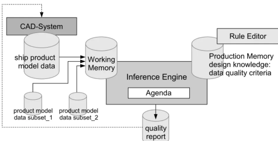
The aim of the research and development project QualiSHIP is to improve the quality and productivity of the ship design and production process by developing knowledge based tools for an automated quality control of product model data (http://www.qualiship.de). To make a tool usable at any step in the design process, e.g. before data are exchanged between different tasks (in-house or between companies), all intra- and inter-organizational processes are to be supported. The QualiSHIP project partners are two shipyards, working with different CAD-systems and building different types of ships: FR. Lürssen Werft and Wadan Yards Germany. Together with the design agent SMK-Ingenieurbüro intra-organizational vertical and horizontal data exchange scenarios based on different CAD-systems, as well as the inter-organizational exchange of product data at different stages in the design process are performed. Atlantec Enterprise Solutions contributes to the project with its neutral data repository and integrated rule engine implementation. The Center for Marine Information Systems (CeMarIS) at the University of Rostock is responsible for the rule based checking procedures and rule formulation. Germanischer Lloyd adds to the scenarios by implementing computer aided approval procedures and corresponding data quality control procedures.
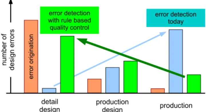
To increase the ship design and production productivity it is widely acknowledged that ship product model data errors of any kind should be detected and corrected as early as possible in the process chain. The exponential rule states that the costs for the error correction increase by an exponential function: at each phase further downstream the process chain between error origination and detection, the exponent of the cost function increases by more than one.
To supply the engineers with a tool to detect errors and/or data quality problems as early as possible, a software system is developed which allows for the formulation of quality criteria with which the ship product model data must comply. An automated check of the product model data against the formulated criteria results in a report which gives advice to the engineers on how to improve the actual product data model. Figure 3.1 shows the results achieved from the process analysis. It is shown that today the majority of errors obviously originate from the detailed design. However the majority
of design problems are detected not until the production phase. The implementation of an automated quality control procedure will shift the error detection upstream and therefore contributes to substantial cost reduction and time savings.
error detection today detail design er ror ori g in at io n production production design number o f de sign errors error detection with rule based
quality control
Fig. 3.1: Quality control of ship product data results in an upstream shift of error detections
For the complete process analysis, the ship design process is split into five main phases: project planning, basic design, detail design, generating of manufacturing information, and finally, manufacturing. During the planning and design process phase, a ship product data model is created which is being constantly developed and revised. At different stages drawings are derived from the 3D-model and submitted to e.g. the classification society for technical surveillance or passed on to manufacturing preparation. The product data model in any case forms the fundamental basis from which various kinds of manufacturing information are derived. Throughout the overall process the data representation undergo a large number of exchanges, conversions, and redesigns due to changes. This causes the fundamental risk of information loss and/or corruption. As the consequences of errors become more and more serious the later they are discovered, it is crucial to check the product model data as early as possible to make sure that the 3D model data are correct, consistent and fully represent the actual design stage. Having a tool to cross check the derived data with the “truth” represented by the 3D product data model will ensure the data quality and will therefore contribute to reduce costs for expensive corrections in the downstream manufacturing processes. For many ship projects design work is subcontracted to external design agents. As design agents usually work for multiple shipyards at different levels of cooperation with different CAD-systems and different shipyard specific standards and demands at the same time, the engineers constantly have to observe different project settings which are crucial with respect to the quality of their design work. This situation increases the probability of errors substantially. A tool to check the product data for consistency with predefined rules which are configurable for each project will generate a higher reliability of the product model data and therefore will contribute to increase the efficiency in the cooperation.
3.2.1 Quality Control for Ship Structures Data Models
To define the fundamental requirements on the quality of a ship product data model, shipyards and cooperating design agents were interviewed. Engineers involved in the design as well as the production process or being responsible for these processes reported actual problems according to their specific knowledge and experience. To limit the number of process steps in the scope of the survey and to narrow down the amount of data to be checked in the design process, only those tasks which are affected by errors and at the same time have a major impact on the overall performance were taken into account for further consideration.
The information given by many experienced engineers from several maritime companies utilizing different well known CAD-systems was fed into a data base. The data base finally comprehended more than 180 “typical problem types” occurring in the different phases of the ship design process and at the multiple interfaces between them. The documented problems can be classified into six major types:
Identification Attributes: problems concerning attributes in the 3D product model
serving to identify parts,
Material Logistics: problems caused by not observed limitations in raw material and
stock material,
Manufacturing Requirements: problems caused by not observed requirements from the
manufacturing of parts and specially assemblies,
Weld Preparation: as an important subset of category above found worth for a separate type category: special problems occurring at weld preparation,
Design Practice: problems caused by not observing state of the art design solutions in
specific design contexts,
Drawing Conventions: problems due to the neglect of conventions for drawing.
These problem types are further subdivided into sub-categories each with a focal point allowing to further classify the identified problems. This approach finally resulted in 24 principle error types occurring in the design and manufacturing data generation of naval and commercial ships.
The error analysis furthermore revealed that four general criteria: a) existence, b)
compliance with predefined conventions, standards, c) conclusiveness and d) consistency can be identified which are generally to be fulfilled. The application
specific problem types and the four general criteria result in a matrix in which all quality criteria are documented.
As an example the criteria for the identification of parts in form of position numbers is briefly discussed – this criteria is judged to be of high priority for an automated quality control process. Although there are many different, partially complex structured rule sets to be considered, the “position number” quality criteria are simple examples which will serve to explain the general quality criteria in this context.
As engineers normally work on several projects with different requirements at the same time, it was found a challenge for them to observe all specific conventions and relevant parameters for each project consistently. All CAD-systems used to generate the product model data offer sophisticated and efficient functions to set position numbers for all kinds of parts. Using these functions can however result in a parts numbering which is not correct with respect to the project specific conventions. The four general criteria for this example can be used to formulate the following quality criteria to be observed:
Existence: This criterion obviously is very simple and can be formulated
straightforwardly: Every part must have a position number assigned to it. Parts with no position number will cause potentially major problems at the latest in the production preparation process.
Compliance with predefined conventions: Position numbers have to be conforming to
yard or project specific conventions according to a specific naming and/or numbering system. Examples found for position numbering are: Each part type gets his own range of numbers (e.g. plates from 300 to 399, stiffeners from 400 to 499 etc.). Position numbers are four digits and have to begin with the figure “1” for profiles and plates. Standard parts like brackets or clips have their own unique number, some are project specific and some are identical for all projects. The representation of position numbers on drawings has to follow specific require-ments (e.g. usage of a combination of symbols and digits).
Conclusiveness: This criterion formulates requirements on position numbers of one part
in relationship to other parts: parts not being identical are not allowed to have the same position number assigned to. However it was found necessary for some projects that due to the production process applied, identical parts can have different position numbers assigned to. To determine the identity of parts, the shape formed by the inner and outer contours and the material type have to be analyzed thoroughly. Especially for an exact shape analysis observing allowed tolerances, the identity check of parts requires the application of complex, sometimes time consuming geometrical and topological algorithms.
Consistency: The three criteria listed above are formulated with respect to ship product
model data represented in a 3D-product model. In case of multiple representations of these data, e.g. additionally in drawings and derived manufacturing information in text files or spread sheets, the consistency between these representations has to be ensured: e.g. the position number for every part has to be the same in all representations of that part. Resolution of conflicts of this type is still a major challenge which results in time consuming and error prone engineering change management tasks.