READ THESE TERMS AND CONDITIONS CAREFULLY BEFORE USING THIS WEBSITE. https://nrc-publications.canada.ca/eng/copyright
Vous avez des questions? Nous pouvons vous aider. Pour communiquer directement avec un auteur, consultez la
première page de la revue dans laquelle son article a été publié afin de trouver ses coordonnées. Si vous n’arrivez pas à les repérer, communiquez avec nous à [email protected].
Questions? Contact the NRC Publications Archive team at
[email protected]. If you wish to email the authors directly, please see the first page of the publication for their contact information.
NRC Publications Archive
Archives des publications du CNRC
Access and use of this website and the material on it are subject to the Terms and Conditions set forth at
NRC activities and publications, 1999-2001
Rogers, D. W. O.; Kawrakow, I.; Klassen, N.; McCaffrey, J.; Ross, C. K.;
Shortt, K. R.; van der Zwan, L.; Daskalov, G.
https://publications-cnrc.canada.ca/fra/droits
L’accès à ce site Web et l’utilisation de son contenu sont assujettis aux conditions présentées dans le site LISEZ CES CONDITIONS ATTENTIVEMENT AVANT D’UTILISER CE SITE WEB.
NRC Publications Record / Notice d'Archives des publications de CNRC: https://nrc-publications.canada.ca/eng/view/object/?id=eee8fb5b-8cdc-492f-8324-6071d71b07aa https://publications-cnrc.canada.ca/fra/voir/objet/?id=eee8fb5b-8cdc-492f-8324-6071d71b07aa
NRC Activities and Publications, 1999–2001
Report to CCRI(I) Meeting, BIPM
May 23 –25 2001
D.W.O. Rogers, I. Kawrakow, N.V. Klassen, J. P. McCaffrey, C.K. Ross,
K.R. Shortt, L. van der Zwan, and G. Daskalov
Ionizing Radiation Standards
Institute for National Measurement
National Research Council of Canada
Ottawa, Canada K1A 0R6
Phone: (613) 993-2715
Facsimile (613) 952-9865
e-mail [email protected]
April 10, 2001
This document is available on-line at
Contents
1 Introduction 3
1.1 Presence on the WWW . . . 3
1.2 IRS Staff . . . 3
2 Air-kerma standards 4 2.1 Low-energy X-ray standards . . . 4
2.1.1 Electric field lines in the MEES Free-air chamber . . . 6
2.2 60Co air-kerma standards . . . . 8
2.2.1 Monte Carlo correction factors for air-kerma standards . . . 8
2.2.2 Accuracy of Spencer-Attix cavity theory . . . 8
3 Absorbed-Dose Standards 11 3.1 60Co absorbed-dose comparisons . . . 11 3.2 Water calorimeter . . . 11 3.2.1 Heat Defect . . . 12 3.2.2 All-Glass Vessel . . . 12 3.2.3 Electron Vessel . . . 12
3.2.4 Conductive Heat Correction . . . 13
3.3 Fricke Dosimetry . . . 14
3.4 Beam Quality Specification . . . 15
3.5 Radiochromic film . . . 15
4 Dosimetry Protocols 15 4.1 AAPM’s TG-61 on 40 - 300 kV X-ray beam dosimetry in radiotherapy and radiobiology . . . 15
4.2 AAPM’s TG–51 on external beam dosimetry . . . 16
4.2.1 Re-calculation of Pwall factors for plane-parallel chambers . . . 16
4.2.2 Measurements of kQ in high-energy photon beams. . . 16
4.2.3 Improved energy-range relationship for electron beams . . . 17
5 Monte Carlo simulation 18 5.1 Distribution of the EGS4 system . . . 18
5.2 The new version of EGS: EGSnrc . . . 18
5.2.1 Physics changes in EGSnrc . . . 18
5.2.2 System changes in EGSnrc . . . 19
5.2.3 User-code changes in EGSnrc . . . 20
5.3 EGS Windows . . . 20
5.4 OMEGA Project – BEAM Code . . . 20
5.4.1 Simulation of Linear accelerators . . . 21
5.4.2 Catalogue of Photon Spectra . . . 21 CONTENTS
5.5 Fast Monte Carlo calculations for treatment planning . . . 21
6 Brachytherapy with DOM 22
7 IRS Publications, 1999 – 2001 23
8 References cited in report 28
1
Introduction
The Ionizing Radiation Standards group at NRC is part of the Institute for National Mea-surement Standards (INMS). There are 17 full-time staff positions (2 empty at present), 4 of whom are on “soft” money. There are 3 others working with the group on a part-time basis and three full-part-time graduate students. There are regular visitors from other laboratories. Most of the research work of the group results in publications and a full list of these is given in section 7.
With the recent retirement of Dr Dallas Santry, who was responsible for the radioac-tivity laboratory at NRC, this laboratory has been mothballed. INMS is in the middle of a strategic planning effort in which there is a reasonable expectation that there will be significant new resources. It is our goal to re-establish the radioactivity laboratory with these increased resources.
The previous report in this series was in 1999 (CCRI(I)/99–24).
1.1
Presence on the WWW
NRC, INMS and IRS have each established a presence on the WWW. NRC has a home page as does the Institute for National Measurement Standards. This latter page includes links to information such as our directory of services and a map of how to find us in Ottawa. We also maintain a series of research oriented sites which can all be reached from http://www.irs.inms.nrc.ca/inms/irs/irs.html. The main site contains links to a number of papers which are fully on-line (in html) as well as available as postscript files and in some cases as pdf files. There are also pages devoted to the dissemination of the EGS4 and EGSnrc Monte Carlo systems and the BEAM system for simulating radiotherapy units (discussed in sections 5.1 and 5.4 below).
1.2
IRS Staff
Research Officers
George Daskalov: discrete ordinates techniques for brachytherapy treatment planning Iwan Kawrakow: theoretical dosimetry and Monte Carlo techniques
Norman Klassen: absorbed dose measurements and radiation chemistry John McCaffrey: air kerma standards
David Rogers: dosimetry protocols, Monte Carlo simulation (group leader) Carl Ross: radiation dosimetry, responsible for linear accelerator
Dallas Santry: radioactivity measurements/standards (retired April, 2001)
Jan Seuntjens: radiation dosimetry, dosimetry protocols (moved to McGill, Jan 2000) Ken Shortt: radiation dosimetry, responsible for60Co standards
Len van der Zwan: radiation dosimetry, responsible for x-ray standards Technical Officers
Feridoun Farahvash: electronics Leo Heistek: electronics (1/3 time)
Dave Hoffman: ion chamber calibration services Matt Kosaki: responsible for linac operations
Ernesto Mainegra: support of Monte Carlo calculations
David Marchington: instrument maker, experimental assistant Stewart Walker: electronics
Blake Walters: OMEGA/BEAM and EGSnrc computing support Other Support
Heather Matchett: secretary/organiser
Michel Proulx: computing system manager (part time) Physics Graduate Students
Nina Kalach: MSc student working on beam quality specification (Rogers) Ken Ngongchu: MSc student working on gel dosimetry (Shortt and Santyr) Steve Davis: MSc student working on TLD dosimetry (Shortt and Ross)
2
Air-kerma standards
2.1
Low-energy X-ray standards
The group provides low-energy x-ray standards from 10kV to 300 kV. These are based on free-air chambers. Calibrations based on these standards form a significant fraction of the calibration service provided by the group, including a recently initiated quality assurance service for providers of TLD personnel monitoring services (similar to the service offered for many years in the 60Co beams).
In 1999 the plates in our medium energy x-ray free air chamber (the MEES) were removed to be re-ground to ensure they were flat. An older set of plates were re-installed in the interim and based on comparisons of calibration factors obtained with the respective plate systems, we are confident that the two standards agree with each other at about the 0.05% level.
Table 1 summarises the results of a comparison with the BIPM done in 1998 (although the final report is not yet complete). This comparison was done by calibrating 3 NE2571 chambers at both NRC and the BIPM.
We have also taken part in a comparison held at NIST. NRC took part by calibrating a set of 2 ion chambers at NRC and at NIST using the NIST and NPL standards. The
preliminary results indicate that in the M100, M150, M200 and M250 beams, NRC and NIST agree within 0.22% and by using the results of the NPL/NIST comparison in the same beams we can establish that the NRC standards are within 0.15% of the NPL standards except for the M250 beam where the NRC standard is 0.36% higher than the NPL standard. This in contrast to the comparison with BIPM where the NRC beam at 250 kV is 1% lower than the BIPM standard.
Table 1: Comparison of the NRC and BIPM air-kerma standards for x-rays in the medium energy range using 3 cylindrical ionization chamber, type NE2571.
kV HVL NK,N RC/NK,BIP M
100 4.0 mm Al 0.9940
135 0.49 mm Cu 0.9927
180 0.99 mm Cu 0.9904
250 2.53 mm Cu 0.9900
During the comparisons with the BIPM, we became more aware of the issue of reaching stability when calibrating ion chambers, especially at lower kerma rates. Figure 1 shows the response of an NE2571 chambers as a function of its accumulated air kerma, after not being in a radiation field for several months. These response curves depend strongly on the chamber’s recent irradiation history. In figure 1, one could be fooled into thinking that the response was stable after reaching 200 mGy, only to have the response decrease by a further 0.4%. It is important in any calibration procedure to have a careful procedure which ensures that equilibrium has been reached.
Figure 1: The radiation conditioning history of an NE2571 chamber which has not been exposed to radiation for several months.
2.1.1 Electric field lines in the MEES Free-air chamber
The NRC medium energy exposure standard (MEES) is a free-air chamber of conventional parallel-plate design.1 The high voltage and guard-collector plates are 58 cm long and
35 cm high. They are separated by a gap of 26 cm. The collector is 10 cm long and is centered on the guard plate. It is isolated from the guard by 0.25 mm air gaps.
The collecting volume of the free-air chamber is defined by the aperture through which the x-ray beam enters the chamber and by the electric field lines which terminate on the collector plate. If the field lines are perpendicular to the ion chamber plates, then the length of the collecting volume will be equal to the length of the collector plate plus one-half the width of the air gap on each side of the collector.
A series of 24 guard bars is used to help establish a uniform electric field in the MEES free-air chamber. A resistive divider network is used to establish a linear potential gradient between the plates. Tests by Henry and Garrett1 showed that the guard bars
could be shorted in pairs or in groups of four without having any significant impact (less than 0.06%) on the chamber response.
During a recent series of measurements, a sudden change in the response of the MEES was observed. Upon investigation, it was discovered that two adjacent guard bars had shorted. In order to understand how the electric field lines are perturbed by shorted guard bars, the electric field distribution within the chamber was solved numerically.
The commercial software package, FlexPDE, was used to construct a two-dimensional model of the chamber. The chamber was considered to be of infinite extent at right angles to the beam axis. The model included the exterior shielding box, which is maintained at ground potential, the high voltage plate, which is held at 5000 V, the guard and collector assembly at ground potential and the 24 guard bars at each end of the chamber.
The Laplace equation,
∇ · ∇V = 0, (1)
where V is the potential, was solved by FlexPDE using the finite element method. The electric field can then be obtained at any point as
E = −∇V. (2)
Once the electric field was calculated, a separate program was used to follow the field lines within the chamber. In particular, the field line that passes through the centre of the gap between the guard and collector was followed until it crossed the central axis of the chamber. Using the intersection of this field line with the central axis, the length of the collecting volume could be determined.
The behaviour of the field lines at the upstream guard-collector gap is shown in figure 2 for several different configurations of the guard bars. With all the guard bars connected, the field line which passes through the centre of the guard-collector gap is indistinguishable from a straight line perpendicular to the guard-collector plane. However, for the other guard bar configurations shown in figure 2, this field line deviates significantly from the
239 240✁ 241✁ 242✁ 243✁ distance along guard−collector plane /mm
0 5 10 15
distance from guard−collector plane /cm
Field lines at the upstream guard−collector gap
24 bars 16,17 shorted
1, 2 shorted
no bars
Figure 2: Calculated field lines for different guard bar configurations. These results pertain to the upstream gap between the guard and collector. Similar results apply to the downstream gap, except that the field lines are reflected about a vertical line passing through the centre of the gap.
straight line. The effect on the chamber response, ∆R, can be calculated using
∆R = − 2∆x (lcol+ g)
, (3)
where ∆x is the offset of the field line along the central axis, lcol is the length of the
collector and g is the width of the guard-collector gap. The following table summarises the calculated changes in response and compares the results to those cases for which the change has also been measured.
Table 2: Calculated and measured variation in response of the free air chamber as the guard bar configuration is varied.
Offset ∆R (calculated) ∆R (measured)
(mm) (%) (%)
24 bars 0.0 0.0 –
No bars +2.5 -5.0 –
1,2 shorted +0.43 -0.86 -0.69
16, 17 shorted -0.22 +0.44 +0.27
The calculations predict the right trend and magnitude for the change in chamber response. However, the calculated change in response is somewhat larger than measured. It is well known that other aspects of chamber design and operation can influence the electric field distribution. These include the degree to which the high voltage and guard-collector plates are parallel, the degree to which the guard and guard-collector are coplanar and any voltage difference between the guard and collector. Although these effects have been studied extensively by the pioneers of free-air chamber design, the ability to model in detail the electric field distribution may shed new light on the behaviour of these devices.
2.2
60Co air-kerma standards
The60Co air-kerma standards are based on cavity ion chambers with graphite walls.2 The
other major calibration services of the group are based on these standards.
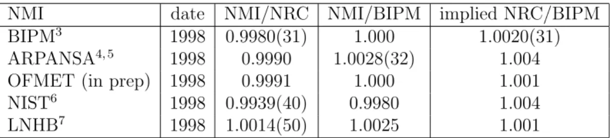
In the last few years NRC has carried out formal comparisons of the 60Co air-kerma
standards with NIST, BIPM, ARL (ARPANSA), LNHB and OFMET and the results of these comparisons are summarised in table 3. When three laboratories compare their standards in pairs, one can predict one of the results based on the other two, as done in column 5 of the table. This gives an estimate of the overall consistency of the comparisons. Table 3 shows that the degree of consistency is reasonable in all cases, with the loop closing at the 0.2% level or better.
Table 3: Results of comparisons of NRC’s standard for air-kerma in a60Co beam
NMI date NMI/NRC NMI/BIPM implied NRC/BIPM
BIPM3 1998 0.9980(31) 1.000 1.0020(31)
ARPANSA4, 5 1998 0.9990 1.0028(32) 1.004
OFMET (in prep) 1998 0.9991 1.000 1.001
NIST6 1998 0.9939(40) 0.9980 1.004
LNHB7 1998 1.0014(50) 1.0025 1.001
NRC has also become involved with some SIM comparison work in the last 2 years. In 1999 there were preliminary measurements made by the standards labs of Mexico (ININ), Argentina (CNEA) and Chile (CCEN). The staff of these labs brought ion chambers to NRC to be calibrated and these calibrations were compared to the calibrations each NMI had determined for the chambers. More recently a series of comparisons are being done by circulating a set of ion chambers to be calibrated in terms of air kerma and absorbed dose. This is being done in conjunction with the IAEA and the following national laboratories are also involved: NIST, CNEA, IRD (Brazil), ININ, and IVIC-LSCD (Venezuela).
2.2.1 Monte Carlo correction factors for air-kerma standards
In some recent work we have done extensive measurements and Monte Carlo calculations of ion chambers used as primary standards. By comparison of a plane-parallel and cylindrical chamber’s absolute response, and by comparing the dramatically varying response of the plane parallel chamber as a function of angle, we have shown that the Monte Carlo calculated Kwall corrections are in much better agreement with the measured data than
the extrapolated Kwall factors which lead to inconsistencies of more than 2% between
the air-kerma measured by the two chambers. This work is described in more detail in a separate submission to the CCRI meeting.8
2.2.2 Accuracy of Spencer-Attix cavity theory
At the previous meeting we reported an on-going study of the accuracy of Spencer-Attix cavity theory as applied in standards labs.9 This work has since been completed and
published.10 This paper has several interesting results.
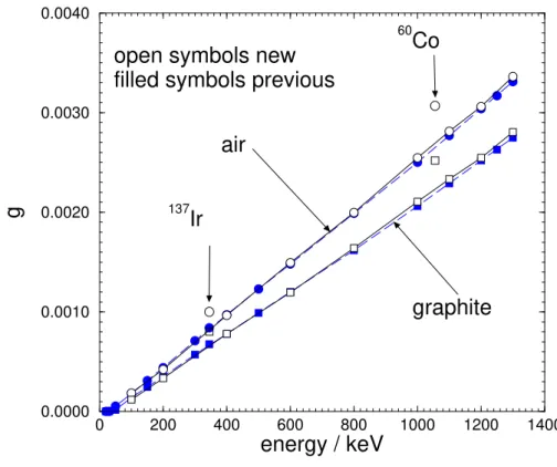
The first is a careful evaluation of g, the fraction of an electrons energy lost via radiative processes while slowing down. Figure 3 presents these values for electrons stopping in air and graphite. The good news is that the new values, which are calculated in much more detail, are only about 2% higher than the commonly used values of Boutillon.11 This is
in good agreement with the results of Seltzer12 who found that radiative yields calculated
with complete Monte Carlo calculations were about 3% higher than those calculated in the CSDA approximation used in ICRU Report 37. It must be emphasised that a 2% change in a value of of 0.003 which is subtracted from 1.0, is totally negligible.
0 200 400 600 800 1000 1200 1400
energy / keV
0.0000 0.0010 0.0020 0.0030 0.0040g
137Ir
60Co
air
graphite
open symbols new
filled symbols previous
Figure 3: Values of g for air and graphite. The closed symbols represent the values from Boutillon11 and the open symbols are values calculated using Monte Carlo calculations (for E ≥ 100 keV). The new 60Co values and the 192Ir values are plotted at the mean energy of the spectrum used.13, 14 The statistical uncertainties are typically 0.5% but the overall uncertainty is determined by the 5% uncertainty in the underlying radiative stopping power from ICRU Report 37.15 Taken from ref.10
The second general result concerns the calculation of stopping-power ratios (sprs) for graphite to air for use in air-kerma standards. In the standard codes we have used in the past at NRC to calculate these values, we have used electron spectra calculated in a small volume of graphite, about the size of our standard chamber. These calculations included photons attenuated and scattered in the walls and (filled) cavity region. However, the standard theory for ion chambers demands an spr which is calculated without any scatter or attenuation in the chamber. We have modified our codes to handle this case, so that now the calculated sprs are independent of the geometry used in the calculation. Figure 4 shows the difference between method 1 (the old way) and method 2 (the new, correct way). The good news is that the difference is very small, perhaps completely negligible?
10 100 1000 energy/keV 0.9999 1.0000 1.0001 1.0002 1.0003 1.0004 1.0005 1.0006 (L( ∆ )/ ρ )M1 /(L( ∆ )/ ρ )M2 192 Ir 60 Co
Figure 4: Ratio of Spencer-Attix graphite to air stopping-power ratios calculated using method 1 (including scatter and attenuation in the wall) and method 2 (geometry independent with no scatter) The value of ∆ for the calculations is 10 keV. From ref.10
A third result is that Spencer-Attix cavity theory works to within about 0.05% at the
60Co energies and within 0.25% at 192Ir energies. This is shown in figure 5 which plots
KSA, the correction factor needed to correct Spencer-Attix cavity theory. This result only
applies for graphite-walled chambers and hold primarily because graphite and air are so similar. To get this good a result requires use of graphite to air stopping-power ratios which are a function of ∆.10
10 20 30 40 50 ∆/keV 0.9965 0.9970 0.9975 0.9980 0.9985 0.9990 0.9995 1.0000 1.0005 1.0010 1.0015 KSA BIPM NIST filled − 60Co empty − 192Ir NRC
Figure 5: Values of KSA for 192Ir and 60Co beams, calculated when stopping-power ratios have values of ∆ = 4V/A. They are plotted as a function of the value of ∆ used in each case. At 60Co and 192Ir the departure from Spencer-Attix theory for the NIST chambers is less than 0.1%, and largest for the 50 cm3 chamber (∆ = 42 keV). From ref.10
The final result is that the small polystyrene insulator in the NRC standard chamber has an 0.4% effect on the chamber response at 60Co energies and this will require a
revision upwards of the NRC standard by the corresponding 0.4%.
3
Absorbed-Dose Standards
In the last 2 years the demand for 60Co absorbed-dose calibrations in Canada has
in-creased dramatically with the introduction of the TG-51 protocol. This protocol has been formally recommended by the Canadian Organisation of Medical Physicists for clinical use in Canada and is being steadily implemented across the country.
3.1
60Co absorbed-dose comparisons
In the last few years NRC has performed formal comparisons of absorbed dose to water standards with NIST, BIPM, ARPANSA, OFMET and LNHB. In all cases the60Co
stan-dards were compared and in the cases of OFMET and LNHB two accelerator beam qual-ities were compared. The results are being written up and are mostly published.4, 6, 7, 16
The 60Co results are summarised in Table 4. The degree of consistency between the
bilateral comparisons taken in groups of 3 is demonstrated in column 5 of the table and is generally at the 0.08% level or better except for the comparison with NIST where the data fail to close at the 0.3% level.
Table 4: Results of comparisons of NRC’s standard for absorbed dose in a60Co beam
NMI date NMI/NRC NMI/BIPM implied NRC/BIPM
BIPM16 1998 1.0024(52) 1.000 0.9976(52)
ARPANSA4, 17 1998 1.0031 1.0008 0.9977
OFMET (in prep) 1998 1.0025 1.000 0.9975
NIST6, 18 1998 1.0050(60) 0.999 0.9947
LNHB7 1998 1.0020(54) 0.9988 0.9968
3.2
Water calorimeter
Work at several standards laboratories has demonstrated that the sealed water calorimeter is a suitable device for establishing the absorbed dose to water. The overall uncertainty is not dramatically better than that achieved using a graphite calorimeter. However, the measurement program is simpler, especially for higher energies, because no transfer procedure is required.
The proceedings of the 1999 NPL workshop on calorimetry contains three papers relating to the water calorimetry program at NRC. One19 contains a description of the
NRC calorimeter as well as some of the results obtained for photon beams. Another20
reports on the effects of convective heat flow when the calorimeter is operated at room temperature. The third21describes the characteristics and behaviour of the OFMET (now
metas) water calorimeter which was built as part of a collaborative arrangement between the two laboratories.
3.2.1 Heat Defect
In a recent publication22 we used a reaction model to calculate the heat defect for several
aqueous systems. A subsequent investigation revealed that the value in the literature for one of the rate constants in the model was incorrect. This led to a significant error in the calculated heat defect at 4oC for H
2/O2 water, which is water saturated with a flow of
43% H2 and 57% O2, by volume. The model was revised, and used to simulate our water
calorimetry measurements. For a dose rate of 1.5 Gy/min, the predicted heat defect at 4oC for the H
2/O2 system is about -0.021. This result is in satisfactory agreement with
the measured response of the H2/O2 system relative to the N2 and H2 systems. The
calculations predict a slightly different value, namely -0.025, for the heat defect at room temperature. A comparison of calorimetry measurements at 4oC and 21oC should be able
to test this prediction.
3.2.2 All-Glass Vessel
The major technical difficulty associated with water calorimetry is the need to establish aqueous systems having a well-defined heat defect. This means that the laboratory must have access to a source of high-purity water and the ability to saturate the water with at least one type of gas, and preferably two. It order to circumvent this difficulty, we have constructed an all-glass vessel which is filled with an appropriate aqueous system and sealed off. The geometry of the first vessel we have constructed this way is very similar to the cylindrical vessels used in our earlier studies.19 We have measured the response of
the all-glass vessel filled with hydrogen-saturated water over a period of several months. Its response is stable, and consistent with the absorbed dose to water obtained using our standard vessel.
3.2.3 Electron Vessel
Our standard vessel design is not well suited for measurements in electron beams. We have constructed a glass vessel of pancake design, having a diameter of about 10 cm and a thickness of about 4 cm. The entrance window has been ground down to a thickness of 1 mm, while the exit window has a thickness of about 2 mm. By using curved thermistor probes we can locate the point of measurement close to the entrance window.
Because the dose gradients associated with electron beams tend to be steeper than those associated with photon beams, we anticipate that it will be necessary to stir the water more frequently to re-establish thermal equilibrium. In order to shorten the time for the vessel to come to equilibrium, we have added a small, magnetically driven, stirrer in a cavity at the bottom of the vessel.
We have used the electron vessel to measure the absorbed dose in a 20 MV photon beam. Because of the proximity of the thermistor probes to the vessel walls, the conductive heat correction is of the opposite sign, and somewhat larger, than for our cylindrical vessel. Nevertheless, it is still less than a 0.5% correction, and the absorbed dose determined for 20 MV x-rays is in good agreement with other calorimetry data.
3.2.4 Conductive Heat Correction
Because the specific heat of glass is significantly smaller than that of water, most of the heat deposited in the glass vessel and probes by the radiation is transferred to the water. This heat is then transported by conduction to the measuring point and perturbs the measured temperature rise. (Because the calorimeter is operated at 4oC there is no
convective heat transfer). We use the commercial software package, FlexPDE, to solve the conductive heat transfer problem and thus extract a correction factor which must be applied to each calorimeter run.
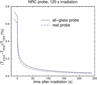
In our previous work, we modelled the thermistor probes as solid glass. We have extended the model to account for the fact that the real probe is a glass shell filled with epoxy. Figure 6 compares the excess heat for these two models.
0 50 100 150✁ 200 250✁
time after irradiation (s)
0.0 0.2 0.4 0.6 0.8 (T actual −T ideal )/T ideal (%) NRC probe, 120 s irradiation all−glass probe real probe
Figure 6: Effect of the thermistor probe on the temperature at the measuring point, which is taken to be the centre of the thermistor bead. The solid line is the result if the probe is modelled as a solid glass rod 0.5 mm in diameter, while the dashed line is the result if it is modelled as a glass shell filled with epoxy. The temperature rise at the measuring point with the probe present is denoted by Tactual while the corresponding temperature rise for homogeneous water is denoted by Tideal.
It is clear that a solid glass rod is an adequate model of the probe.
After the calorimeter has come to thermal equilibrium, the pre-drift for the first run will be linear. However, as excess heat from the vessel wall is conducted to the measuring point, the pre-drifts of the subsequent runs will generally show some curvature. This means that the correction for excess heat may be different for each run in a sequence.
Figure 7 shows the calculated post-drifts for several runs from a sequence of 10 runs. The temperature rise for homogeneous water has been subtracted, thus leaving just the effect of the glass probes and wall on the temperature rise. For each run, a linear fit to the pre-drift was subtracted from the complete run. Then a straight line was fitted to each post-drift, and the line extrapolated to mid-run.
In this case, the effect for the first run (0.18%) is significantly less than that for the
200 250✁ 300 350✁
time from beginning of run / s 0.0 0.1 0.2 0.3 0.4 0.5 0.6 (T actual −T ideal )/T ideal (%) NRC vessel, 120 s irradiation Run 1 Run 2 Run 3 Run 10 mid−run end of run post−drift
Figure 7: Effect of the excess heat from the thermistor probes and vessel wall for the NRC cylindrical vessel. The effect is shown for a series of 120 s irradiations. Each run consists of a pre-drift of 120 s, an irradiation of 120 s and a post-drift of 120 s. An additional 120 s drift occurs before the pre-drift of the next run is initiated. Note that 20 s of data immediately after the end of each run is not used in the fitting procedure because of the rapidly-changing effect due to the thermistor probe (figure 6). The temperature rise at the measuring point with the vessel and probes present is denoted by Tactual while the corresponding temperature rise for homogeneous water is denoted by Tideal.
subsequent runs (about 0.28%). The effect depends on the vessel geometry, the irradiation time and the run sequence. For another realistic situation, we have noted that the effect for the first run was very small, but for the second run it was 0.5%. Thus, the correction for excess heat can be an important factor in the accurate determination of the absorbed dose to water using water calorimetry.
3.3
Fricke Dosimetry
As discussed in our previous report to CCRI, we have measured a variation in the G value for Fricke dosimetry as a function of beam energy and these results were published in 1999.23 The variation between60Co and high-energy x-rays (20, 30 MV) was measured
to be 1.007(±0.003). In a recent paper we have used this variation to correct a variety of measured values of kQ from the literature.24
In related work, we have modelled the radiation chemistry involved in the Fricke dosimeter in order to predict accurately the value of G(Fe3+) for saturated and
air-free Fricke dosimeter, for low-dose rate and pulsed irradiations and for a variety of oxygen and Fe2+ concentrations. The model is in good agreement with published data. This
work is summarised in a separate contribution to the CCRI meeting.25
3.4
Beam Quality Specification
There has been considerable controversy regarding beam quality specification in photon beams, which started about the time of the last meeting of CCRI.24, 26–29 The issue boils
down to the fact that TPR20
10 does not specify beam quality for dosimetry purposes in
all realistic accelerator beams, whereas %dd(10)x does. On the other hand, if one is only
interested in clinical beams, TPR20
10 may be an adequate specifier. In fact, TPR2010 would
be an adequate specifier if all measurements were in clinical beams. However, many of the beams in standards labs are not clinical, and there is no accepted definition of what is a “clinical beam” or even a “clinic-like” beam. We have done extensive work in this area and in a separate submission to CCRI30 it is shown that:
1. For a much wider variety of clinical beams than investigated previously, TPR20 10 is a
good beam quality specifier (with the exception of the MM50 racetrack microtron); 2. For many non-clinical beams, usually heavily filtered beams in standards labs,
TPR20
10 is also a good beam quality specifier;
3. TPR20
10 is not a good beam quality specifier for a broad range of realistic beams
found in standards laboratories;
4. By measuring %dd(10)x and TPR2010 for a beam, it is possible to establish whether
TPR20
10 is a good beam quality specifier or not, by seeing if these two parameters
satisfy a particular criterion.
5. If either %dd(10)x or TPR2010 is known in a clinical beam, one can deduce the other
from the relationships found.
3.5
Radiochromic film
A project has been carried out to use GafChromic film to measure backscatter factors in x-ray beams. The results are presented separately.31
4
Dosimetry Protocols
4.1
AAPM’s TG-61 on 40 - 300 kV X-ray beam dosimetry in
radiotherapy and radiobiology
This protocol for kV X-ray dosimetry will be published in June, 2001 in Medical Physics.32
Although they have both moved on, the two senior authors of this protocol (Ma and Seuntjens) did all the initial work on the protocol while at NRC.
4.2
AAPM’s TG–51 on external beam dosimetry
This protocol was published33 just after the previous CCRI meeting in 1999. As
men-tioned above, it has been been formally recommended for use in Canada by the Cana-dian Organization of Medical Physicists. It has been the basis of the Houston RPC’s dosimetry quality audits throughout North America since January 1, 2000. A variety of papers have been published showing that clinical dosimetry changes by about 1% for photon beams (an increase in dose assigned, the exact magnitude depends on the ratio of ND,w/NK). For electron beams the change can be somewhat larger, up to 3% in some
cases. A summary of the expected changes has been published34 and is available on-line
at http://www.irs.inms.nrc.ca/inms/irs/why use tg51 article/comp.html.
4.2.1 Re-calculation of Pwall factors for plane-parallel chambers
When plane-parallel chambers are calibrated in a 60Co beam for later use in an electron
beam33, 35, 36 one needs to know the correction factor, P
wall, which corrects for the fact
that the chamber wall is not made of water if calibrated in water, or is not made entirely of the buildup cap material if calibrated in air. The AAPM protocols have based these values on calculations done with EGS437 but there is a 1% systematic uncertainty in
these values. We have undertaken to recalculate these factors using the EGSnrc code38, 39
which is known to have a systematic uncertainty of about 0.1% or less40 when calculating
ion chamber response. The new values differ from the previous values by up to 2% in one extreme case (for a Capintec chamber) and are generally closer to experimentally measured values than in the past. More details are found in a separate submission to the CCRI meeting.41
4.2.2 Measurements of kQ in high-energy photon beams.
We have published24 an extensive set of measurements of k
Q for 6 types of
cylindri-cal chambers (NE2571, NE2581, PTW-N30001, Capintec PR06C, Exradin A12, and NE2611A) in photon beams ranging from 60Co - 30 MV. We used 3 chambers of each
type, except for the NE2571 where we used 5 chambers. The chambers were extensively involved in work at 60Co and low-energy x-ray beams to verify the consistency of their
behaviour prior to being used in the high energy photon beams.
We performed ion chamber calibrations against the sealed water calorimeter operated at 4oC. The overall uncertainty on the measurement of an individual chamber’s value of
kQ was 0.38%.
The results of the measurements have been discussed in our previous report and will not be discussed in detail here. The most important results are that:
1. the measured values of kQagree with those published in TG-51 with an rms deviation
of 0.41% for roughly 60 measurement points;
2. the NRC measured data and data from other labs agree much better when the %dd(10)x beam quality specifier is used rather than TPR2010.
3. when comparing the differences of our kQ measurements and calculations with an
analysis in terms of air-kerma protocols with the same underlying calculations but expressed in terms of a compound conversion factor CQ, we observe that a system
making use of absorbed dose calibrations and calculated kQ values, is more accurate
than a system based on air-kerma calibrations in combination with calculated CQ
(rms deviation of 0.48% versus 0.67% respectively).
4.2.3 Improved energy-range relationship for electron beams
In North America, electron beam energy is based on the measured range of the electron beam in water and the relationship between the energy and the range is determined by Monte Carlo calculations. With the improved EGSnrc code available, it was found that the previously calculated relationship needed to be updated. Figure 8 shows the relationship between Eo and R50 for an electron beam from a point source at 100 cm.
The dashed curve labelled RB86/TG-25 was calculated using an early version of EGS442
and recommended for use by the AAPM’s TG-25.43 The solid line with no symbols was
calculated using the latest version of the EGS4 code system and the solid line with the diamonds was calculated with EGSnrc.39, 44 The implication is that for a given value of
R50, the true initial energy of the beam decreases by about 1.5% to 2.5% for beams of
interest in radiotherapy. Although this simple type of relationship is widely used, it must be recalled that it breaks down and does not relate the true mean energy of the beam to R50.45 0 2✁ 4 ✂ 6 ✄ 8 ☎ 10 12✁ 14✂ 16 18☎ 20 R50 / cm 2.30 2.40 2.50 2.60 2.70 Eo / R 50 / (MeV/cm)
point source of electrons 100 cm from water phantom
DOSRZ(V3.2) DOSRZnrc spin on RB86 TG−25 point source of e− 100 cm from water
Figure 8: Eo/R50 as a function of R50 for broad beams of electrons coming from a point source 100 cm from the water.
5
Monte Carlo simulation of radiation transport
5.1
Distribution of the EGS4 system
NRC has played a major role in developing and disseminating the EGS4 code sys-tem for Monte Carlo simulation of electrons and photons in arbitrary geometries.37
On Jan 3, 1997, a version of the Unix based system was released via the internet at http://www.irs.inms.nrc.ca/inms/irs/EGS4/get egs4.html and this is still being widely used and frequently downloaded.
5.2
The new version of EGS: EGSnrc
In March 2000 we taught a course based on a completely new version of the EGS4 system, called EGSnrc.39 This system was released publicly in May 2000 and is available along
with its documentation at http://www.irs.inms.nrc.ca/inms/irs/EGSnrc/EGSnrc.html. EGSnrc represents a major advance with respect to EGS4 and EGS4/PRESTA38 and
in particular it resolves the various problems that EGS4/PRESTA had when calculating ion chamber responses.40
The following shortened extract from the EGSnrc manual39 is a brief summary of the
improvements in EGSnrc compared to EGS4.
5.2.1 Physics changes in EGSnrc
• A completely new electron transport algorithm is used which removes all known shortcomings of the EGS4/PRESTA algorithm. If the geometry permits, the new algorithm can take much larger steps with better accuracy than previously. As it crosses a boundary, it goes into single scattering mode to ensure an accurate boundary crossing.
• A new multiple scattering theory is used which gets around the shortcomings of Moliere multiple scattering theory. It seamlessly goes from a single scattering mode for short steps to a multiple scatter mode for long steps.
• Within the new multiple scattering theory an option has been added to include relativistic spin effects in the cross section instead of just the Rutherford cross section which underlies Moliere theory.
• If desired, it is possible to do the entire calculation modelling elastic scattering in a single scattering mode.
• A relaxation feature has been added which allows creation and following of fluores-cent photons from K, L, M shells, Auger electrons and Coster-Kronig electrons. • If relaxation is not being modelled, then a photo-electron in EGSnrc carries the
entire energy of the incident photon. This is a better approximation in most cases 5 MONTE CARLO SIMULATION
than dumping the binding energy locally and subtracting the binding energy from the photo-electron’s energy (as done in EGS4).
• Sampling the angular distribution of the photo-electron is available as an option. • Bound compton scattering can be simulated or Klein-Nishina Compton scattering. • Bremsstrahlung angular sampling has been changed from a fixed angle
approxima-tion to allowing the angular distribuapproxima-tion to be sampled in one of two ways.
• A bug was fixed in the bremsstrahlung photon energy sampling routine which af-fected simulations for which AP was not small relative to the electron energy. Doing this led to a complete rewrite of the sampling routine which also increased its effi-ciency.
• A second bremsstrahlung photon energy sampling option was added which uses the more accurate NIST differential cross sections.
• PEGS4 has been modified to pick up the data files which scale the radiative cross sections to produce the NIST/ICRU 37 radiative stopping powers.
• A variety of variance reduction techniques which were commonly used with EGS4 have been “built in” with EGSnrc to improve the efficiency (viz bremsstrahlung splitting is done within the routine BREMS, Russian Roulette of secondary charged particles, range rejection is implemented very efficiently since the particle range and distance to the nearest boundary are already calculated on every step).
• The Moller sampling routine was corrected as first done in the 1997 release of EGS4. • The efficiency of the annihilation sampling routine has been improved.
• The sampling of the azimuthal angle has been recoded and saves a noticeable amount of time in a real calculation (2% in one example).
5.2.2 System changes in EGSnrc
• The various source files have been rationalised and various add-on features to EGS4 have been made part of EGSnrc.
• Two options for random number generator are available (RANLUX and RANMAR). • The default for calculating sines is a function call because modern machines do this rapidly and the table lookup method is known to be inaccurate for very small angles. • The entire code has been written using IMPLICIT NONE. Further, all declarations have been done using $REAL and $INTEGER constructs which allow conversion to running double precision by redefining 2 macros.
5.2.3 User-code changes in EGSnrc
• Four of the standard NRC user codes for cylindrical geometry problems are now distributed with the system, DOSRZnrc, FLURZnrc, CAVRZnrc and SPRRZnrc. • The above user codes have been extensively reworked to use a new generalised input
package which makes it much easier for the user to generate the input files since the inputs are text oriented. Also, the geometry and physics transport inputs are common for all codes.
• The output routines have been reworked to avoid the use of VAX extensions to Fortran which were not available with many unix compilers.
• The user codes have been cleaned up to some extent although not as much as desirable! The main user codes systematically use $IMPLICIT-NONE and $REAL, $INTEGER constructs to allow compatibility with EGSnrc and the ability to change to double precision at will.
• a bug in the energy sampling routine which caused problems in some cases has been removed. An entirely new code which is faster and more accurate is used now.
• All the user codes can be run in parallel on an arbitrary number of computers. The results are combined at the end in a post-processing step.
5.3
EGS Windows
EGS Windows is a 3-D interactive graphics tool for displaying the output of Monte Carlo simulations. It was originally dependent on proprietary SGI software. How-ever in 1999 it was ported to run on non-proprietary software, and in particu-lar there are executables available which run on Linux with no further installa-tion of libraries. The new version is considerably enhanced over earlier versions and is now documented.46 Further information and the software are available at
http://www.irs.inms.nrc.ca/inms/irs/EGS Windows/distribution.html.
5.4
OMEGA Project – BEAM Code
The development of the BEAM code for Monte Carlo simulation of accelerator beams47 is
on-going at NRC with the release of a version based on EGSnrc expected in Oct 2001. The code is being very widely used and has been licensed commercially to various treatment planning companies.
The BEAM course is becoming an annual event with 6 courses being held since 1995 and the 7-th to be held this October. For further information about the code or the course see: http://www.irs.inms.nrc.ca/inms/irs/BEAM/beamhome.html.
5.4.1 Simulation of Linear accelerators
The BEAM code has been carefully benchmarked against the 10 and 20 MV photons beams from the NRC linac.48 These data are useful since most accelerator benchmarks
are for proprietary machines whereas in this case full information about the accelerator could be released. The agreement between calculations and experiment is excellent.
In a related project a wide variety of commercial linacs have been simulated (Varian, Siemens, Electa machines) and a method developed for determining several essential pa-rameters which are usually not well known, in particular the mean energy of the incident electron beam and the radius of the incident electron beam.
5.4.2 Catalogue of Photon Spectra
In an effort to provide a well documented source of photon spectra for use in Monte Carlo calculations, a catalogue is being developed.49 It will be available on-line soon at
http://www.irs.inms.nrc.ca/inms/irs/spectra/spectra.html. We strongly encourage others to send us any similar spectra that they have calculated or measured so that we can make them all available.
5.5
Fast Monte Carlo calculations for treatment planning
The development of fast particle transport simulation algorithms is essential for the rou-tine clinical use of Monte Carlo (MC) techniques in radiation treatment planning (RTP). The VMC++code50–52is 50 to 150 times faster than traditional MC packages such as EGS4
or EGSnrc, being at the same time sufficiently accurate for RTP purposes. VMC++ is
partially based on the VMC53, 54 and XVMC algorithms55, 56 but incorporates a variety of
improvements in the modelling of the underlying physical processes (e.g. the exact multi-ple scattering theory of ref.57), a newly developed technique, called STOPS (Simultaneous
Transport Of Particle Sets), and use of quasi-random sequences for electron and photon transport. Most of the efficiency increase in VMC++ and (X)VMC is due to the
random-hinge electron transport algorithm, first proposed by the PENELOPE group58 and later
shown to have an order of magnitude smaller truncation error than other algorithms,59
to-gether with a boundary crossing algorithm that permits transport through several regions in a single condensed history step. Figure 9 shows the relative efficiency of a VMC++
calculation for a 20 MeV 10x10 cm2 electron beam incident on a water phantom as a
function of the number of particles per set when using quasi-random (dotted line) or pseudo-random (full line) number sequence. It is apparent from this figure that VMC++
is up to 5 times more efficient than algorithms that do not employ STOPS and quasi-random numbers.
The VMC++ code has been licensed to a Canadian company (MDS Nordion) and will
soon appear in the Helax and Theraplan treatment planning systems.
1 10 100 1000
particles per set
1 2 3 4 5 6
relative efficiency
20 MeV electrons, 10x10 cm2 beam
quasi−random numbers pseudo−random numbers
Figure 9: The relative efficiency of VMC++ simulations as a function of the number of particles per set using pseudo-random (solid line) and quasi-random (dotted line) sequences.
6
Brachytherapy Treatment Planning using the
Dis-crete Ordinates Method
The Discrete Ordinates Method (DOM) computer code PARTISN (LANL Report LA-12969-M) has been implemented for investigation of 3-dimensional DOM radiation trans-port simulations - specifically, their accuracy and feasibility for implementation in brachytherapy conformal treatment planning relative to Monte Carlo. The PARTISN code is the next level of development of the DANTSYS DOM code used in our previ-ous studies. PARTISN incorporates higher-order spatial- differencing schemes, adaptive mesh refinement (AMR), and has capabilities for parallel multiprocessor computation. An important contribution of our study is the development of a broad 3-energy group cross section library which reduces dramatically the computer resources’ requirements. Currently, our ongoing 3D DOM simulations are extensively benchmarked against Monte Carlo. The preliminary results of this study indicate that:
• PARTISN simulations yield accurate (within 5around I-125 brachytherapy sources in clinically realistic geometries.
• At present, our DOM 3D simulations require about 1 hour on our 250MHz SGI workstation (single processor). This, together with the order of magnitude longer CPU times observed in our efficient voxel-based 3D Monte Carlo calculations for brachytherapy indicate the potential of implementing 3D DOM calculations in brachytherapy treatment planning.
7
IRS Publications, 1999 – 2001
Publications of Staff of IRS: 1999–2001
Institute for National Measurement Standards
National Research Council of Canada
Ottawa, K1A-OR6
Refereed Publications
[1] J. Borg and D. W. O. Rogers, Spectra and Air-Kerma Strength for Encapsulated
192Ir Sources, Med. Phys. 26, 2441 – 2444 (1999).
[2] N. V. Klassen, K. R. Shortt, J. P. Seuntjens, and C. K. Ross, Fricke dosimetry: the difference between G(Fe3+) for 60Co γ-rays and high-energy x-rays, Phys. Med.
Biol. 44, 1609 – 1624 (1999).
[3] Y. Li, J. Rungis, K.-T. Kim, Y. M. Cho, T. R. McComb, J. G. Dunn, L. V. der Zwan, and D. Hoffman, Inter-Laboratory Comparison of High Direct Voltage Resistance Dividers, IEEE Transactions: Instrumentation and Measurement 48, 158 – 161 (1999). [4] G. Mora, A. Maio, and D. W. O. Rogers, Monte Carlo simulation of a typical 60Co
therapy source, Med. Phys. 26, 2494 – 2502 (1999).
[5] P. R. Almond, P. J. Biggs, B. M. Coursey, W. F. Hanson, M. S. Huq, R. Nath and D. W. O. Rogers, AAPM’s TG–51 Protocol for Clinical Reference Dosimetry of High-Energy Photon and Electron Beams, Med. Phys. 26, 1847 – 1870 (1999). [6] D. W. O. Rogers, Correcting for electron contamination at dose maximum in
photon beams, Med. Phys. 26, 533 – 537 (1999).
[7] D. W. O. Rogers and C. L. Yang, Corrected relationship between %dd(10)x and
stopping-power ratios, Med. Phys. 26, 538 – 540 (1999).
[8] J. Seuntjens and H. Palmans, Correction factors and performance of a 4oC sealed
water calorimeter., Phys. Med. Biol. 44, 627 – 646 (1999).
[9] G. G. Zhang, D. W. O. Rogers, J. E. Cygler, and T. R. Mackie, Monte Carlo investi-gation of electron beam output factors vs size of square cutout, Med. Phys. 26, 743 – 750 (1999).
[10] J. Borg, I. Kawrakow, D. W. O. Rogers, and J. P. Seuntjens, Monte Carlo study of Spencer-Attix cavity theory at low photon energies, Med. Phys. 27, 1804 – 1813 (2000).
[11] G. M. Daskalov, R. S. Baker, R. C. Little, D. W. O. Rogers, and J. F. Williamson, Two-Dimensional Discrete Ordinates Photon Transport Calculations for Brachyther-apy Dosimetry Applicationsy, Nuclear Science and Engineering 134, 121 – 134 (2000).
[12] G. M. Daskalov, R. S. Baker, D. W. O. Rogers, and J. F. Williamson, Dosimetric Modeling of the MicroSelectron High-Dose Rate 192Ir Source by the Multigroup
Discrete Ordinates Method, Med. Phys. 27, 2307 – 2319 (2000).
[13] I. Kawrakow, Accurate condensed history Monte Carlo simulation of electron transport. I. EGSnrc, the new EGS4 version, Med. Phys. 27, 485 – 498 (2000). [14] I. Kawrakow, Accurate condensed history Monte Carlo simulation of electron
transport. II. Application to ion chamber response simulations, Med. Phys. 27, 499 – 513 (2000).
[15] I.Kawrakow and M. Fippel, Investigation of variance reduction techniques for Monte Carlo photon dose calculation using XVMC , Phys. Med. Biol. 45, 2163 – 2184 (2000).
[16] D. W. O. Rogers, Comment on “On the beam quality specification of high-energy photons for radiotherapy dosimetry [Med. Phys. 27 434 – 440 (2000)] , Med. Phys. 27, 441 – 444 (2000).
[17] J. P. Seuntjens, C. K. Ross, K. R. Shortt, and D. W. O. Rogers, Absorbed-dose beam quality conversion factors for cylindrical chambers in high-energy photon beams, Med. Phys. 27, 2763 – 2779 (2000).
[18] D. Sheikh-Bagheri, D. W. O. Rogers, C. K. Ross, and J. P. Seuntjens, Comparison of measured and Monte Carlo calculated dose distributions from the NRC linac, Med. Phys. 27, 2256 – 2266 (2000).
[19] K. Shortt, J. Shobe, and S. Domen, Comparison of Dosimetry Calibration factors at the NRCC and the NIST, Med. Phys. 27, 1644 – 1654 (2000).
[20] C. M. Ma, C. W. Coffey, L. A. DeWerd, C. Liu, R. Nath, S. M. Seltzer, and J. Seuntjens, AAPM protocol for 40 – 300 kV x-ray beam dosimetry in radiotherapy and radiobiology: Report of Task Group 61, in press, Medical Physics 28 (2001). [21] G. M. Daskalov, R. S. Baker, D. W. O. Rogers, and J. F. Williamson, Multigroup
discrete ordinates modelling of 125 6702 seed dose distributions using a broad
energy-group cross section representation, Med. Phys. (submitted, 2001).
[22] G. M. Daskalov and J. F. Williamson, Monte Carlo-aided dosimetry of the new BEBIG IsoSeed 103Pd interstitial brachytherapy seed, Med. Phys. (submitted,
2000).
[23] K. R. Shortt, C. K. Ross, J. P. Seuntjens, F. Delaunay, A. Ostrowsky, P. Gross, and E. Leroy, Comparison of dosimetric standards of Canada and France for Photons at 60Co and linac energies, Phys. Med. Biol. (submitted, 2000).
Published in Proceedings
[1] J. Borg, J. P. Seuntjens, I. Kawrakow, and D. W. O. Rogers, Monte Carlo study of cavity theory at low energies, Proceedings of the 1999 COMP Annual Meeting (Canadian Organization of Medical Physicists, Edmonton, Alberta) , 123 – 125 (1999). [2] T. W. M. Grimbergen, A. H. L. Aalbers, B. J. Mijnheer, J. Seuntjens, H. Thierens, J. V.
Dam, F. W. Wittkamper, and J. Zoetelief, The NCS code of practice for dosimetry of low and medium energy x-rays, in Kilovoltage x-ray beam dosimetry for radiotherapy
and radiobiology: Proceedings of a workshop, edited by C.-M. Ma and J. P. Seuntjens,
pages 55 – 68, Medical Physics Publ., Madison, WI, USA, 1999.
[3] C.-M. Ma, C. W. Coffey, L. A. Dewerd, C. Liu, R. Nath, S. M. Seltzer, and J. P. Seuntjens, Status of Kilovoltage X-ray Beam Dosimetry in Radiotherapy, in Kilovoltage
x-ray beam dosimetry for radiotherapy and radiobiology: Proceedings of a workshop, edited
by C.-M. Ma and J. P. Seuntjens, pages 27 – 42, Medical Physics Publ., Madison, WI, USA, 1999.
[4] C.-M. Ma, A. X. Li, and J. P. Seuntjens, Study of Dosimetry Consistency for Kilo-voltage X-ray Beams, in KiloKilo-voltage x-ray beam dosimetry for radiotherapy and
radiobiology: Proceedings of a workshop, edited by C.-M. Ma and J. P. Seuntjens, pages
69 – 87, Medical Physics Publ., Madison, WI, USA, 1999.
[5] C.-M. Ma and J. P. Seuntjens, Correction factors for ion chamber waterproofing sleeves in Kilovoltage x-ray beams, Proceedings of a workshop on Kilovoltage X-ray Beam Dosimetry, Stanford University, April 1997 , 179 – 194 (1999).
[6] C.-M. Ma and J. P. Seuntjens, Ratios of Mass Energy-Absorption Coefficients and Backscatter Factors for Biological Tissues, Proceedings of a workshop on Kilovoltage X-ray Beam Dosimetry, Stanford University, April 1997 , 261 – 278 (1999).
[7] J. Seuntjens, A. H. L. Aalbers, T. W. M. Grimbergen, B. J. Mijnheer, H. Thierens, J. V. Dam, F. W. Wittkamper, J. Zoetelief, M. Piessens, and P. Piret, Suitability of diamond detectors to measure central axis depth kerma curves for low and medium–energy x–rays, in Kilovoltage x-ray beam dosimetry for radiotherapy and
radiobiology: Proceedings of a workshop, edited by C.-M. Ma and J. P. Seuntjens, pages
227 – 238, Medical Physics Publ., Madison, WI, USA, 1999.
[8] J. P. Seuntjens and C.-M. Ma, Dose conversion factors and depth scaling for tissue dose calculations in kilovoltage x-ray beams , Proceedings of the 1999 COMP Annual Meeting (Canadian Organization of Medical Physicists, Edmonton, Alberta) (1999). [9] J. P. Seuntjens, L. V. der Zwan, and C.-M. Ma, Type dependent correction factors for
cylindrical chambers for in-phantom dosimetry in medium energy x-ray beams, in Kilovoltage x-ray beam dosimetry for radiotherapy and radiobiology: Proceedings of
a workshop, edited by C.-M. Ma and J. P. Seuntjens, pages 159 – 174, Medical Physics
Publ., Madison, WI, USA, 1999.
[10] K. R. Shortt, Five dosimetric comparisons at Cobalt-60 energy involving NRC in 1998, Proceedings of the 1999 COMP Annual Meeting (Canadian Organization of Medical Physicists, Edmonton, Alberta) , 135 – 137 (1999).
[11] C. L. Yang, D. W. O. Rogers, K. R. Shortt, and L. Van der Zwan, Ion recombination in ion chambers in continuous radiation, Proceedings of the 1999 COMP Annual Meeting (Canadian Organization of Medical Physicists, Edmonton, Alberta) , 23 – 25 (1999).
[12] M. Fippel, I. Kawrakow, F. N¨usslin, and D. W. O. Rogers, Implementation of several variance reduction techniques into the XVMC Monte Carlo algorithm for photon beams, in The Use of Computers in Radiotherapy, XIIIth Int’l Conf., Heidelberg, edited by W. Schlegel and T. Bortfeld, pages 406 – 408, Springer-Verlag, Heidelberg, 2000. [13] I. Kawrakow and M. Fippel, VMC++, a fast MC algorithm for radiation treatment
planning, in The Use of Computers in Radiotherapy, XIIIth Int’l Conf., Heidelberg, edited by W. Schlegel and T. Bortfeld, pages 126 –128, Springer-Verlag, Heidelberg, 2000. [14] J. Medin, J. Seuntjens, N. Klassen, C. Ross, and G. Stucki, The OFMET Sealed Water
Calorimeter, in Proceedings of NPL Workshop on Recent Advances in Calorimetric
Absorbed Dose Standards, edited by A. J. Williams and K. E. Rosser, pages 65–73,
National Physical Laboratory, Teddington, UK, 2000.
[15] D. W. O. Rogers and R. Mohan, Questions for comparison of clinical Monte Carlo codes, in The Use of Computers in Radiotherapy, XIIIth Int’l Conf., Heidelberg, edited by W. Schlegel and T. Bortfeld, pages 120 – 122, Springer-Verlag, Heidelberg, 2000. [16] C. K. Ross, J. P. Seuntjens, N. V. Klassen, and K. R. Shortt, The NRC Sealed Water
Calorimeter: Correction Factors and Performance, in Proceedings of NPL Workshop
on Recent Advances in Calorimetric Absorbed Dose Standards, edited by A. J. Williams
and K. E. Rosser, pages 90–102, National Physical Laboratory, Teddington, UK, 2000. [17] J. P. Seuntjens, I. Kawrakow, and C. K. Ross, Revisiting Convective Motion in
Stag-nant Water Calorimeters Operated at Room Temperature, in Proceedings of NPL
Workshop on Recent Advances in Calorimetric Absorbed Dose Standards, edited by A. J.
Williams and K. E. Rosser, pages 103–119, National Physical Laboratory, Teddington, UK, 2000.
[18] M. Fippel, M. Alber, M. Birkner, W. Laub, F. N¨usslin, and I. Kawrakow, Inverse treat-ment planning for radiation therapy based on fast Monte Carlo dose calculation, in Proceedings of the Monte Carlo 2000 Meeting Lisbon, in press, 2001.
[19] I. Kawrakow and D. W. O. Rogers, The EGSnrc System, a status report, in
Pro-ceedings of the Monte Carlo 2000 Meeting Lisbon, in press, 2001.
[20] D. W. O. Rogers, Monte Carlo techniques for primary standards of ionizing radi-ation and for dosimetry protocols, in Proceedings of the Monte Carlo 2000 Meeting
Internal Reports
[1] D. W. O. Rogers and I. Kawrakow and N. V. Klassen and C. K. Ross and J. P. Seuntjens and K. R. Shortt and L. Van der Zwan and J. Borg and G. Daskalov, NRC Activities and Publications, 1997–1999: Report to CCRI(I) Meeting, BIPM, CCRI(1)99–24 (1999).
[2] D. W. O. Rogers and J. P. Seuntjens, Photon beam quality specification for com-parisons of absorbed dose to water, BIPM document CCRI(1)99–25 (BIPM, S`evres, France) (1999).
[3] M. Holmes, Correlated Sampling in DOSXYZ, NRC Report PIRS-0509Bi (1999). [4] C. M. Ma, D. W. O. Rogers, and B. Walters, DOSXYZ99 Users Manual, NRC Report
PIRS 509b(revD) (1999).
[5] D. W. O. Rogers and J. Treurniet, Monte Carlo calculated wall and axial non-uniformity corrections for primary standards of air kerma, NRC Report PIRS–663, NRC, Ottawa, 1999.
[6] J. P. Seuntjens, C. K. Ross, N. V. Klassen, and K. R. Shortt, A status report on the NRC sealed water calorimeter, Technical Report PIRS–584, NRC Canada, Ottawa, K1A OR6, 1999.
[7] J. A. Treurniet and D. W. O. Rogers, BEAM, DOSXYZ and BEAMDP GUI User’s Manual, NRC Report PIRS 0623(rev A) (1999).
[8] B. R. B. Walters and D. W. O. Rogers, Monte Carlo estimates of %dd(10)X for
the NPL photon beams, NRC Report PIRS–659, NRC, Ottawa, 1999.
[9] P. J. Allisy-Roberts, D. T. Burns, K. R. Shortt, and C. K. Ross, Comparison of the air kerma standards of the NRC and the BIPM for 60Co γ rays, Rapport BIPM-99/12
(2000).
[10] P. J. Allisy-Roberts, D. T. Burns, K. R. Shortt, C. K. Ross, and J. P. Seuntjens, Com-parison of the standards of absorbed dose to water of the NRC, Canada and the BIPM for 60Co γ rays, Rapport BIPM-99/13 (2000).
[11] I. Kawrakow, The VMC++ code system: Monte Carlo simulation of electron and
photon transport for application in Radiation Treatment Planning, Technical Report PIRS–718, National Research Council of Canada, Ottawa, Canada, 2000.
[12] I. Kawrakow and D. W. O. Rogers, The EGSnrc Code System: Monte Carlo sim-ulation of electron and photon transport, Technical Report PIRS–701, National Research Council of Canada, Ottawa, Canada, 2000.
[13] D. W. O. Rogers, Spencer-Attix water to air mass collision stopping power ratios as a function of depth and beam quality, R50, NRC Report PIRS–719, NRC Canada,
Ottawa, K1A OR6, 2000.
[14] D. W. O. Rogers, I. Kawrakow, J. P. Seuntjens, and B. R. B. Walters, NRC User Codes for EGSnrc, Technical Report PIRS–702, National Research Council of Canada, Ottawa, Canada, 2000.
Other
[1] D. W. O. Rogers, Why use TG–51 instead of TG–21, AAPM Newsletter 25,#5, 17 – 19 (2000).
[2] D. W. O. Rogers, Why To Use TG–51, Interactions (COMP Newsletter) 46,#3, 106 – 107 (2000).
8
References cited in report
[1] W. H. Henry and C. Garrett, The Canadian Standard Free-Air Chamber for Medium Quality X-rays, Canadian Journal of Physics 38, 1677 – 1689 (1960).
[2] K. R. Shortt and C. K. Ross, The Canadian 60Co Exposure Standard, National
Research Council of Canada Report PIRS-0052 (1986).
[3] P. J. Allisy-Roberts, D. T. Burns, K. R. Shortt, and C. K. Ross, Comparison of the air kerma standards of the NRC and the BIPM for60Co γ rays, Rapport BIPM-99/12
(2000).
[4] K. R. Shortt, C. K. Ross, J. P. Seuntjens, R. B. Huntley, L. H. Kotler, and J. F. Boas, A comparison of the Australian and Canadian standards of air kerma and absorbed dose to water for 60Co γ radiation, in preparation (2001).
[5] P. J. Allisy-Roberts, J. F. B. M. Boutillon, and R. B. Huntley, Comparison of the air kerma standards of the ARL and the BIPM for 60Co γ rays, BIPM Report
BIPM–98/4 (1998).
[6] K. Shortt, J. Shobe, and S. Domen, Comparison of Dosimetry Calibration factors at the NRCC and the NIST, Med. Phys. 27, 1644 – 1654 (2000).
[7] K. R. Shortt, C. K. Ross, J. P. Seuntjens, F. Delaunay, A. Ostrowsky, P. Gross, and E. Leroy, Comparison of dosimetric standards of Canada and France for Photons at
60Co and higher energies, Phys. Med. Biol. 46, 2119 – 2142 (2001).
[8] D. W. O. Rogers, J. McCaffrey, I. Kawrakow, and K. R. Shortt, Wall correction factors for graphite walled ion chambers, BIPM document CCRI(1)/01–?? (BIPM, S`evres, France) (2001).
[9] D. W. O. Rogers and I. Kawrakow and N. V. Klassen and C. K. Ross and J. P. Seuntjens and K. R. Shortt and L. Van der Zwan and J. Borg and G. Daskalov, NRC Activities and Publications, 1997–1999: Report to CCRI(I) Meeting, BIPM, CCRI(1)99–24 (1999).
[10] J. Borg, I. Kawrakow, D. W. O. Rogers, and J. P. Seuntjens, Monte Carlo study of Spencer-Attix cavity theory at low photon energies, Med. Phys. 27, 1804 – 1813 (2000).
[11] M. Boutillon, ¯g values from Berger and Seltzer tables (1982), BIPM document CCEMRI(I)/85-18, 1 page (1985).
[12] S. M. Seltzer, Calculation of photon mass transfer and mass energy-absorption coefficients (dosimetry application), Radiation Research 136, 147 – 170 (1993).
[13] D. W. O. Rogers, G. M. Ewart, A. F. Bielajew, and G. van Dyk, Calculation of Electron Contamination in a 60Co Therapy Beam, in “Proceedings of the IAEA
International Symposium on Dosimetry in Radiotherapy” (IAEA, Vienna), Vol 1 , 303 – 312 (1988).
[14] J. Borg and D. W. O. Rogers, Spectra and Air-Kerma Strength for Encapsulated
192Ir Sources, Med. Phys. 26, 2441 – 2444 (1999).
[15] ICRU, Stopping powers for electrons and positrons, ICRU Report 37, ICRU, Wash-ington D.C., 1984.
[16] P. J. Allisy-Roberts, D. T. Burns, K. R. Shortt, C. K. Ross, and J. P. Seuntjens, Comparison of the standards of absorbed dose to water of the NRC, Canada and the BIPM for 60Co γ rays, Rapport BIPM-99/13 (2000).
[17] P. J. Allisy-Roberts, D. T. Burns, J. F. Boas, R. B. Huntley, and K. N. Wise, Comparison of the standards of absorbed dose to water of the ARPANSA and the BIPM for 60Co γ radiation, Rapport BIPM-99/17 (2000).
[18] P. J. Allisy-Roberts and J. Shobe, Comparison of the standards of absorbed dose to water of the NIST and the BIPM for 60Co γ rays, Rapport BIPM-98/5 (1999).
[19] C. K. Ross, J. P. Seuntjens, N. V. Klassen, and K. R. Shortt, The NRC Sealed Water Calorimeter: Correction Factors and Performance, in Proceedings of NPL Workshop on Recent Advances in Calorimetric Absorbed Dose Standards, edited by A. J. Williams and K. E. Rosser, pages 90–102, National Physical Laboratory, Ted-dington, UK, 2000.
[20] J. P. Seuntjens, I. Kawrakow, and C. K. Ross, Revisiting Convective Motion in Stagnant Water Calorimeters Operated at Room Temperature, in Proceedings of NPL Workshop on Recent Advances in Calorimetric Absorbed Dose Standards, edited by A. J. Williams and K. E. Rosser, pages 103–119, National Physical Laboratory, Teddington, UK, 2000.
[21] J. Medin, J. Seuntjens, N. Klassen, C. Ross, and G. Stucki, The OFMET Sealed Water Calorimeter, in Proceedings of NPL Workshop on Recent Advances in Calori-metric Absorbed Dose Standards, edited by A. J. Williams and K. E. Rosser, pages 65–73, National Physical Laboratory, Teddington, UK, 2000.
[22] N. V. Klassen and C. K. Ross, Water Calorimetry: the Heat Defect, J. Res. Natl. Inst. Stand. Technol. 102, 63 – 74 (1997).
[23] N. V. Klassen, K. R. Shortt, J. P. Seuntjens, and C. K. Ross, Fricke dosimetry: the difference between G(Fe3+) for 60Co γ-rays and high-energy x-rays, Phys. Med. Biol.
44, 1609 – 1624 (1999).
[24] J. P. Seuntjens, C. K. Ross, K. R. Shortt, and D. W. O. Rogers, Absorbed-dose beam quality conversion factors for cylindrical chambers in high-energy photon beams, Med. Phys. 27, 2763 – 2779 (2000).
[25] N. V. Klassen, A model for computer simulations of the Fricke dosimeter, BIPM document CCRI(1)/01–?? (BIPM, S`evres, France) (2001).
[26] D. W. O. Rogers and J. P. Seuntjens, Photon beam quality specification for com-parisons of absorbed dose to water, BIPM document CCRI(1)99–25 (BIPM, S`evres, France) (1999).
[27] P. Andreo, On the beam quality specification of high-energy photons for radiotherapy dosimetry , Med. Phys. 27, 434 – 440 (2000).
[28] P. Andreo, A comparison between calculated and experimental kQ photon beam
quality correction factors, Phys. Med. Biol. 45, L25 – L38 (2000).
[29] D. W. O. Rogers, Comment on “On the beam quality specification of high-energy photons for radiotherapy dosimetry [Med. Phys. 27 434 – 440 (2000)] , Med. Phys. 27, 441 – 444 (2000).
[30] N. Kalach and D. W. O. Rogers, What consitutes a clinic-like radiotherapy beam , BIPM document CCRI(1)/01–?? (BIPM, S`evres, France) (2001).
[31] N. V. Klassen, L. van der Zwan, J. Cygler, and J. P. Seuntjens, Experimental determination and Monte carlo simulations of backscatter factors in clinical kilovolt-age x-ray beams using GafChromic MD-55-2 radiochromic film, BIPM document CCRI(1)/01–?? (BIPM, S`evres, France) (2001).
[32] C. M. Ma, C. W. Coffey, L. A. DeWerd, R. Nath, C. Liu, S. M. Seltzer, and J. Seun-tjens, AAPM protocol for 40 – 300 kV x-ray beam dosimetry in radiotherapy and radiobiology: Report of Task Group 61, Med. Phys. #6, 28 (in press, 2001). [33] P. R. Almond, P. J. Biggs, B. M. Coursey, W. F. Hanson, M. S. Huq, R. Nath and
D. W. O. Rogers, AAPM’s TG–51 Protocol for Clinical Reference Dosimetry of High-Energy Photon and Electron Beams, Med. Phys. 26, 1847 – 1870 (1999). [34] D. W. O. Rogers, Why To Use TG–51, Interactions (COMP Newsletter) 46,#3,
106 – 107 (2000).
[35] P. R. Almond, F. H. Attix, S. Goetsch, L. J. Humphries, H. Kubo, R. Nath, and D. W. O. Rogers, The calibration and use of plane-parallel ionization chambers for dosimetry of electron beams: An extension of the 1983 AAPM protocol, Report of AAPM Radiation Therapy Committee Task Group 39, Med. Phys. 21, 1251 – 1260 (1994).
[36] D. W. O. Rogers, A new approach to electron beam reference dosimetry, Med. Phys. 25, 310 – 320 (1998).


![[PDF] Cours generale pour debuter la programmation avec le langage C | Cours langage c](data:image/gif;base64,R0lGODlhAQABAIAAAP///wAAACH5BAEAAAAALAAAAAABAAEAAAICRAEAOw==)