HAL Id: hal-03155799
https://hal.archives-ouvertes.fr/hal-03155799
Submitted on 2 Mar 2021HAL is a multi-disciplinary open access
archive for the deposit and dissemination of sci-entific research documents, whether they are pub-lished or not. The documents may come from teaching and research institutions in France or abroad, or from public or private research centers.
L’archive ouverte pluridisciplinaire HAL, est destinée au dépôt et à la diffusion de documents scientifiques de niveau recherche, publiés ou non, émanant des établissements d’enseignement et de recherche français ou étrangers, des laboratoires publics ou privés.
Numerical study on the improvement of flow
distribution uniformity among parallel mini-channels
Cyril Pistoresi, Yilin Fan, Lingai Luo
To cite this version:
Cyril Pistoresi, Yilin Fan, Lingai Luo. Numerical study on the improvement of flow distribution uni-formity among parallel mini-channels. Chemical Engineering and Processing: Process Intensification, Elsevier, 2015, 95, pp.63-71. �10.1016/j.cep.2015.05.014�. �hal-03155799�
* Corresponding author. Tel.: +33 240683167; Fax: +33 240683141. E-mail address: [email protected]
1
Pistoresi, C., Fan, Y., & Luo, L. (2015). Numerical study on the improvement of flow distribution
1
uniformity among parallel mini-channels. Chemical Engineering and Processing: Process
2
Intensification, 95, 63–71. https://doi.org/10.1016/j.cep.2015.05.014
3
4
5
Numerical study on the improvement of flow distribution uniformity
6
among parallel mini-channels
7
8
Cyril PISTORESI1, Yilin FAN1, Lingai LUO1*
9
10
1Laboratoire de Thermocinétique de Nantes, UMR CNRS 6607, Polytech' Nantes – Université de
11
Nantes, La Chantrerie, Rue Christian Pauc, BP 50609, 44306 Nantes Cedex 03, France
12
13
ABSTRACT
14
Parallel micro or mini-channels are widely used in various devices of process and energy engineering
15
including micro-reactors, compact heat exchangers and fuel cells. Nevertheless, the flow maldistribution
16
due to the improper design of distributor/collector is usually observed, leading to globally poor
17
performances of these devices. The objective of this study is to optimize the shape of the
18
distributor/collector pipes so as to achieve a uniform flow distribution among an array of parallel
mini-19
channels. A Z-type ladder fluid network with 10 mini-channels in parallel having square section is
20
introduced and investigated. Two methods are used to optimize the shape of distributor/collector pipes: an
21
optimized discrete stairway shape and a continuous tapered shape with an inclined angle varying from 0°
22
to 30°. 3D-CFD simulations are carried out using the ANSYS FLUENT code. Numerical results obtained
23
show that a relatively uniform flow distribution may be reached by the discrete stairway shape or by the
24
continuous tapered shape distributor/collector under very low flow-rate conditions. Larger inclined angle
25
or fewer channels in parallel are favorable for more uniform flow distribution under higher flow-rate
26
2
conditions. Nevertheless the distributor and the collector pipes occupy a large volume so that the entire
27
device is less compact.
28
29
KEY WORDS: Process intensification;
Mini-channels; Flow maldistribution; Shape optimization;30
Distributor
31
1. INTRODUCTION
32
Chemical industries and process engineering are undergoing rapid changes in the 21st century facing
33
the challenges of climate change and energy shortage. Process Intensification (PI) that leads to
34
smaller, less costly, cleaner, safer, higher productivity and more energy efficient technologies is
35
proposed as a new paradigm of process engineering (Stankiewicz and Moulijn, 2002). Particularly, the
36
innovative design of high yield processes or compact equipments has become one of the pressing
37
industrial needs in recent years (Commenge and Falk, 2014).
38
One of the routes to PI is the use of equipments with locally miniaturized structures, i.e. micro or
39
mini-channels (Charpentier, 2005; Luo, 2013; Commenge and Falk, 2014), because of their enhanced
40
heat and mass transfer properties. Miniaturized process and energy equipments can either be heat
41
exchangers (e.g. Fan and Luo, 2008; Fan et al., 2008; Khan and Fartaj, 2011), chemical mixers or
42
reactors (e.g. Hessel et al., 2005; Illg et al., 2010; Guo et al., 2013), fuel cells (e.g. Sung, 2006;
43
Jackson et al., 2014) or integrated multifunctional systems (e.g. Anxionnaz et al., 2008; Guo et al.,
44
2014). Nevertheless, to obtain a comparable productivity with that of conventional equipment, a
45
number of micro/mini-channels should be installed in parallel. This so-called numbering-up process is
46
the key issue for large-scale industrial applications of these miniaturized devices (Al-Rawashdeh et al.,
47
2012; Luo, 2013). Therefore, the fluid distribution uniformity among the parallel channels may play
48
an important role on the global performance improvement of multi-channel equipments.
49
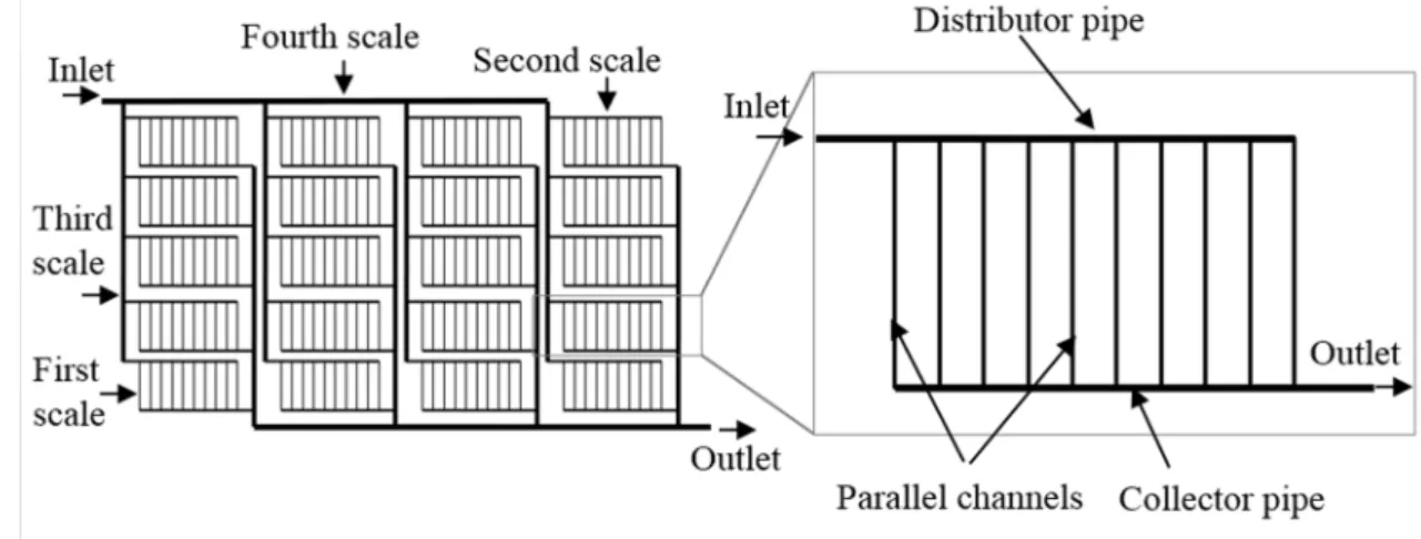
This is particularly true when multi-scale ladder-type fluid networks (Figure 1a) are involved (Saber et
50
al. 2010; Commenge et al. 2011). In order to achieve uniform flow distribution among all parallel
51
channels in the network, the first and essential step is the design of an optimized two-scale elementary
52
Z-type ladder circuit, as shown in Figure 1b. In this elementary fluidic circuit, the single inlet port and
53
3
single outlet port are located on opposite sides of the bundle of parallel cross-channels, meaning that
54
the flow direction is the same in the distributor and the collector pipes. All cross-channels are assumed
55
to have the same geometrical characteristics so that the passage-to-passage maldistribution may be
56
considered as negligible (Rebrov et al., 2011). On the contrary, the improper design of fluid
57
distributor/collector pipes is the main cause of flow maldistribution among the parallel cross-channels.
58
59
60
Figure 1. Multi-scale fluidic network (a) and elementary Z-type ladder circuit (b).
61
62
Many studies have then been focused on how to improve the flow distribution uniformity of the
63
elemental Z-type ladder circuit. It is reported that a relatively uniform distribution may only be
64
approached by making the hydraulic resistance of cross-channels much larger than that of the
65
distributor and collector pipes if the latter have a uniform profile (e.g. Saber et al., 2009; Tondeur et
66
al., 2011a). This usually implies that the distributor and collector pipes are large and encumbering,
67
which is clearly unfavorable for miniaturized devices. Instead of the uniform profile (rectangular or
68
cylinder shape) of the distributor and collector, alternative shapes were proposed, such as triangular or
69
trapezoidal-type (e.g. Kim et al., 1995; Commenge et al., 2002; Pan et al., 2009; Renault et al., 2011)
70
or curvatured shape (e.g. Pan et al., 2008; Cho et al., 2010; Jackson et al., 2014). In particular,
71
Tondeur et al. (2011b) proposed to “taper’’ the profile of distributor and collector pipes in a discrete
72
stairway so that the flow resistances vary linearly with position, which may offer a uniform flow
73
distribution among the parallel cross-channels. Analytical scaling relations were established based on
74
4
the assumptions of Poiseuille flow and negligible singular losses (pressure losses due to
75
divergent/convergent branching). However, no numerical or experimental work has been performed to
76
evaluate the validity and the effective range of this analytical model. The sensitivity of the flow
77
distribution characteristics subjected to different working conditions (e.g. different flow-rate) has not
78
yet been reported.
79
In the present work, the flow distribution properties on a typical Z-type elemental ladder circuit are
80
systematically investigated. We will first describe the design of a mini-channel array with integrated
81
discrete stairway shape distributor and collector pipes based on the scaling relations proposed by
82
Tondeur et al. (2011b). In addition, a continuous model with progressive dimension reduction (or
83
increase) for the distributor pipe (or the collector pipe) is also introduced for comparison. Then,
84
computational fluid dynamics (CFD) simulation results for both models will be reported, under a variety
85
of flow-rate conditions. After that influences of some design parameters including the inclined angle and
86
the number of parallel channels will also be discussed. Finally, main conclusions and perspectives will be
87
summarized.
88
89
2. GEOMETRY AND NUMERICAL PARAMETERS
90
In this section, the design of parallel mini-channel array with integrated distributor/collector pipes
91
based on two models, i.e. the discrete stairway model and the continuous tapered model will be briefly
92
described. The CFD simulation tool and the controlling parameters will be introduced as well.
93
2.1. Geometry of the tested mini-channel array
94
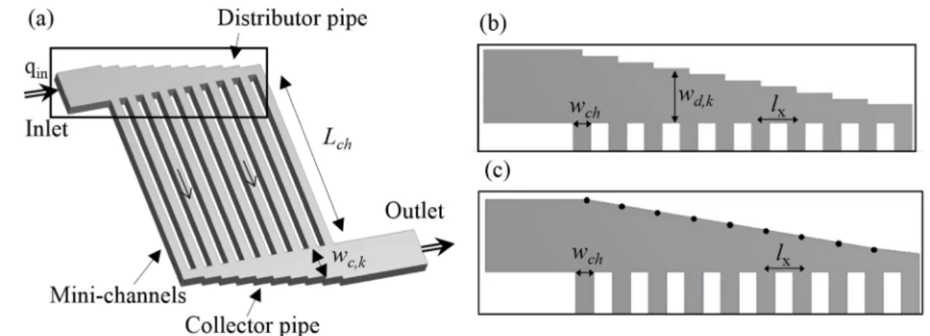
Figure 2 shows a representative schematic view of Z-type elemental ladder fluid circuit. The 3D fluid
95
domain consists of 3 sections: inlet distributor pipe, parallel mini-channel array, and outlet collector
96
pipe. This Z-type elemental ladder network is widely used in different applications such as catalytic
97
reactors, solar receivers, heat exchanger plates, elements of fuel cells, electrochemical microreactors,
98
cooling network of heat sinks, or other process components. For the convenience of potential
99
fabrication, the entire fluidic circuit has the identical channel depth (e=1 mm). There are 10 parallel
100
5
straight channels (N=10) of identical length (Lch=20 mm), width (wch=1 mm) and depth (e=1 mm).
101
They are evenly spaced (lx=2 mm) between the axis of one channel and another. Square cross-section
102
is used for the channels because it is adapted for future experimental visualization of the internal flow
103
using digital camera and optical tracers. Here we introduced a millimetric design (hydraulic diameter
104
of channels being 1 mm) because it may have comparable mixing or heat transfer performances with
105
respect to micro-channels but with higher throughput and lower pressure loss (Luo et al., 2007; Guo et
106
al., 2013). For the convenience of description, these mini-channels are indexed by k from 1 to N from
107
left to right. When a pressure difference is applied between inlet and outlet to cause flow, it will passes
108
through the distributor pipe, the parallel channels and the collector pipe subsequently to reach the
109
outlet. The flow-rate in kth mini-channel is notated as qk.
110
111
112
Figure 2. Geometry of the tested Z-type ladder. (a) mini-channel array; (b) discrete stairway type
113
distributor/collector; (c) continuous tapered distributor/collector
114
115
The flow maldistribution is quantified by two parameters: the relative flow-rate deviation σk and the
116
maldistribution factor MF.117
q
q
q
k k−
=
σ
(1)118
2 11
1
MF
∑
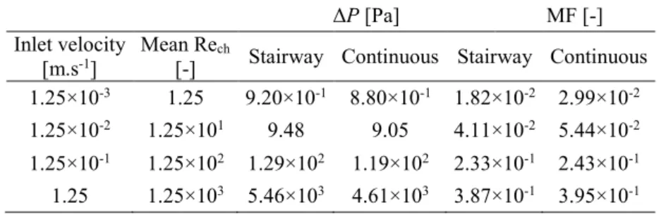
=
−
−
=
N k kq
q
q
N
(2)119
6
where
q
is the mean flow-rate between parallel outlet channels.120
N
q
q
N k k∑
==
1 (3)121
The value of σk indicates the departure of the flow-rate in an individual channel k from the mean value
122
whereas the value of MF indicates the overall flow maldistribution of the whole fluidic network.
123
Uniform flow distribution is achieved when values of σk and MF approach 0.
124
2.2. Discrete stairway model versus continuous tapered model
125
In this subsection, we will firstly describe in detail the design of discrete stairway distributor/collector
126
based on the scaling relations proposed by Tondeur et al. (2011b). The continuous tapered model will
127
also be introduced in the end for comparison.
128
Tondeur et al. (2011b) proposed that uniform flow distribution may be approached by properly
129
arranging the flow resistances on the segments of the distributor/collector pipes. A scaling relation was
130
then established based on the assumption of linear flow/pressure behavior: pure Poiseuille flow,
131
neglecting the inertial terms, neglecting or linearizing the singular effects (Tondeur et al. 2011b).
132
1
, ,+
−
=
k
N
k
R
R
k c k d with k=1…N (4)133
where Rd,k and Rc,k are the flow resistance of kth segment of the distributor pipe or the collector pipe,
134
respectively. Using this scaling relation, a Z-type fluid circuit with uniform cross-flow distribution can
135
be designed. One possible example is schematically shown in Figure 3, where the subscripts d, c, and
136
ch represent the distributor, the collector and the cross-channel, respectively. The mass and pressure
137
conservations can be easily verified while keeping the cross flow-rate all equal (qk=qch).
7 Rc,N=Rc,1/N qout=(N+1) qch qin=(N+1) qch qk=qch qd,1=Nqch Rd,1=Rd,N/N qc,1=qch Rc,1=Rd,N qd,N=qch Rd,N=Rc,1 qc,N=Nqch qd,k=(N-k+1)qch Rd,k=Rd,N/(N-k+1) qc,k=kqch Rc,k=Rc,1/k
139
Figure 3. Flow resistance distribution for uniform flow distribution among parallel channels. Modified from
140
Tondeur et al. (2011b)
141
142
The dimension of each segment of distributor/collector pipes can then be determined by supposing
143
Poisseuille flow in straight channel with rectangular cross-section. The flow resistance in kth segment
144
of the distributor pipe Rd,k may be expressed as (White, 2003):
145
k d k d k h k d k d k dD
ew
u
L
f
R
, , , , , ,=
2
1 ρ
(5)146
where ρ is the density of fluid, Ld,k the length of kth segment, e the depth of channels (1 mm), wd,k the
147
width of kth segment to be determined and ud,k the fluid velocity in the kth segment. Dh,k is the
148
hydraulic diameter for rectangular cross-section and fd,k the friction factor for a straight channel.
149
k d k d k he
w
ew
D
, , ,2
+
=
(6)150
k h k d k d k d k d k du
D
F
F
f
, , , , , ,Re
ρ
µ
=
=
(7)151
where Re is the Reynolds number, μ the viscosity of the fluid and Fd,k the form factor. The values of
152
F
d,kfor rectangular cross-section channels depend on the ratio of channel depth and width
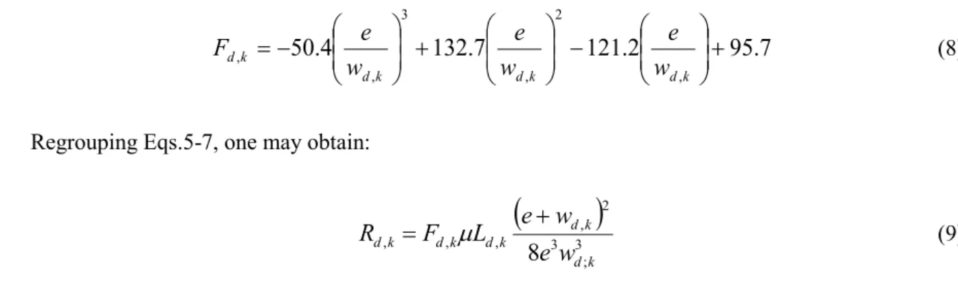
153
(
e/wd,k). Eq. (8) presents the polynomial fitting correlation for F
d,k, based on the data provided
154
from (White, 2003).
155
8
7
.
95
2
.
121
7
.
132
4
.
50
, 2 , 3 , ,
+
−
+
−
=
k d k d k d k dw
e
w
e
w
e
F
(8)156
Regrouping Eqs.5-7, one may obtain:
157
(
)
3 ; 3 2 , , , ,8
k d k d k d k d k de
w
w
e
L
F
R
=
µ
+
(9)158
It may be verified that the flow resistances for segments of collector pipe share the same expression as
159
Eq. 9, by replacing the subscript d with c. By letting wd,N=wc,1=wch=1 mm, the other values of wd,k and
160
wc,k can then be derived using Eqs. 4, 8 and 9, as listed in Table 1.
161
162
Table 1. Widths for the segments of distributor/collector pipes (unit: mm)
163
wd,1 wc,10 wd,2 wc,9 wd,3 wc,8 wd,4 wc,7 wd,5 wc,6 wd,6 wc,5 wd,7 wc,4 wd,8 wc,3 wd,9 wc,2 wd,10 wc,1 4.01 3.66 3.30 2.99 2.65 2.31 1.97 1.63 1.29 1.00164
Figure 2b illustrates the discrete stairway model of the Z-type ladder fluidic circuit, designed
165
according to the morphology presented in Figure 3. Note that a continuous tapered model may also be
166
designed, as shown in Figure 2c, by replacing the stairs by linear profiles from point to point. It may
167
be observed that the linearization leads to an approximate trapezoidal shape for the distributor and
168
collector, with an inclined angle (θ) of about 11.3°. This value is close to the theoretical optimal angle
169
(10.46°) proposed by the model of Renault et al. (2012). The comparison between two models, i.e. the
170
discrete stairway model and the continuous tapered model on their flow distribution properties and the
171
related pressure drop is interesting but never attempted. Numerical tests were then performed for both
172
models for comparison.
173
2.3. Simulation parameters
174
In this study, geometries and meshes were generated using different modules of ANSYS Workbench
175
12.1. Note that due to symmetrical character of the network in the direction of the depth, half of the
176
body had been considered in the analysis. Fluent code V.12.1.4 was used to solve Navier-Stokes
177
equations by finite volume methods. The equation for conservation of mass or continuity is:
178
9 ( ) 0u t
ρ
ρ
∂ + ∇ ⋅ = ∂ (10)179
The momentum conservation equation:
180
( )
u(
uu)
p( )
g F tρ
ρ
ρ
∂ + ∇ ⋅ = −∇ + ∇ ⋅ ∏ + + ∂ (11)181
where u is the velocity, p is the static pressure,
ρ
g and Fare the gravitational body force and182
external body forces,
∏
is the stress tensor which is given by:183
(
T)
2 3 u u uIµ
∏ = ∇ + ∇ − ∇ ⋅ (12)184
where μ is the molecular viscosity, I is the unit tensor.
185
Pure water at constant temperature of 293 K was chosen as working fluid (density ρ=998.29 kg.m-3
186
and viscosity µ=1.003×10⁻³ kg.m-1.s-1). The operational pressure was fixed at 101325 Pa. In this study,
187
simulations were performed under steady state, incompressible and isothermal condition without heat
188
transfer. For simplification, gravity effect and viscous heating were neglected.
189
Velocity inlet normal to the surface was set as the boundary condition for the inlet. Four inlet velocity
190
conditions (Uin) were tested: 1.25×10⁻³ m.s-1; 1.25×10⁻² m.s-1; 1.25×10⁻¹ m.s-1 and 1.25 m.s-1,
191
corresponding to a value of mean channel Reynolds number (Rech) of 1.25, 1.25×101, 1.25×10² and
192
1.25×10³, respectively. The boundary condition of outlet was set as pressure-outlet with zero static
193
pressure. Adiabatic wall condition was applied and no slip occurred at the wall.
194
Laminar flow model was used under very low velocity conditions while k-ε Re-Normalized Group (k-ε
195
RNG) was used for higher velocity conditions because micro turbulences and local vortex may exist.
196
For the pressure-velocity coupling, standard SIMPLE method was used. For discretization, standard
197
method was chosen for pressure and first-order upwind differentiation for momentum. The solution
198
was considered to be converged when the flow-rate at each channel and the inlet static pressure were
199
constant from one iteration to the next (less than 0.5% variation) and the normalized residuals of all
200
monitoring parameters were lower than the order of magnitude of 10-6.
10
2.4. Grid independence study
202
A grid independence study was performed using three structured meshes with different resolutions:
203
coarse mesh (10 segments per millimeter; 0.18 million elements); medium mesh (20 segments per
204
millimeter; 1.65 million elements) and refined mesh (30 segments per millimeter; 5.28 million
205
elements). Simulation results with an inlet velocity of 1.25×10⁻¹ m.s-1 (mean Rech=1.25×10²) indicated
206
a difference of 3.7% on the inlet pressure between the coarse mesh and the refined mesh, and of 0.9%
207
between medium mesh and refined mesh. Mass flow-rates in each mini-channel were also compared,
208
showing a maximum difference of 2.6% between the coarse mesh and the refined mesh, and of 1.3%
209
between the medium mesh and the refined mesh. Hence, the medium mesh was selected as a
210
compromise between the calculation time and the precision.
211
212
3. SIMULATION RESULTS
213
Figure 4 shows the contour of velocity magnitude on the mid-depth surface (symmetry) of the Z-type
214
ladder circuit, under different inlet velocity conditions. Simulation results for the discrete stairway
215
model are presented on the left side of Figure 4 while those for the continuous tapered model are
216
shown on the right side. It can be observed on Figure 4a and 4b that for relatively low inlet velocity
217
conditions (Uin=1.25×10⁻³ m.s-1; mean Rech=1.25 and Uin=1.25×10⁻² m.s-1; mean Rech=1.25×101), both
218
models could provide a relatively uniform flow distribution among the 10 parallel mini-channels. It
219
seems that the velocity profiles in the distributor pipe and in the collector pipe are regular and
220
symmetric, implying that the flow patterns are rather laminar. The impact of singularity losses in
221
converging or diverging bifurcations on the flow distribution uniformity is not significant.
222
11
223
Figure 4. Velocity profiles for the discrete stairway model and for the continuous tapered model. (a)
224
Uin=1.25×10⁻³ m.s-1 (mean Rech=1.25); (b) Uin=1.25×10⁻² m.s-1 (mean Rech=1.25×101); (c) Uin=1.25×10⁻¹ m.s-1
225
(mean Rech=1.25×10²); (d) Uin=1.25 m.s-1 (mean Rech=1.25×10³)
12
On the contrary for relatively high inlet velocity conditions (Uin=1.25×10⁻¹ m.s-1; mean Rech=1.25×10²
227
and Uin=1.25 m.s-1; mean Rech=1.25×10³), flow maldistribution among parallel channels is obvious, as
228
shown on Figure 4c and 4d. This is mainly due to the stronger inertial force at the higher velocity so
229
that the fluid enters the right most channels preferentially. Dead volumes may easily be observed at
230
the entrance zone and outside the exit port of each cross-channel. Small vortex and micro-turbulences
231
may also be observed and the velocity profiles in the distributor and in the collector pipes are no
232
longer symmetrical. These results indicate that more appropriate scaling relations should be
233
developed, taking the internal terms and the singular effects into account. Some recent efforts may be
234
found in references (Midoux and Tondeur, 2014; 2015) for U-type ladder circuits.
235
236
237
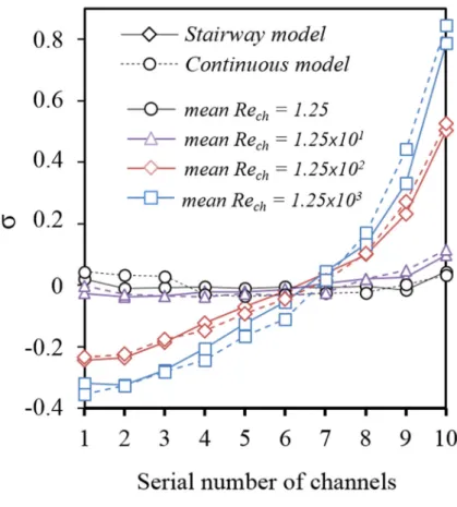
Figure 5. Relative flow-rate deviation (σ) of parallel channels for different inlet velocity conditions
238
239
The increase of flow maldistribution with the increasing inlet velocity may be quantitatively shown in
240
Figure 5, which presents the relative flow-rate deviation σ of each channel for different inlet velocity
241
conditions. For inlet velocity Uin=1.25×10⁻² m.s-1 (mean Rech=1.25×101), the maximum flow-rate
13
deviation is about 0.098 and 0.117 for discrete stairway model and for continuous tapered model,
243
respectively, implying an acceptable flow distribution uniformity. However, the maximum value of σ
244
rapidly increases to 0.78 (stairway model) and 0.84 (continuous model) for inlet velocity Uin=1.25 m.s
-245
1 (mean Rech=1.25×10³), implying significant flow maldistribution.
246
Table 2 gives a comparison on the flow distribution uniformity and inlet/outlet pressure loss of the
247
circuit between the discrete stairway model and the continuous tapered model, for different inlet
248
velocity conditions. Very similar performances may be observed. For the same inlet velocity
249
condition, the discrete stairway model may provide slightly better flow distribution uniformity with
250
respect to the continuous tapered model, but generate higher pressure losses. Especially for inlet
251
velocity Uin=1.25 m.s-1 (mean Rech=1.25×10³), the value of pressure loss is 5.46 kPa for the discrete
252
stairway model, 14.5% higher than that of the continuous tapered model (4.61 kPa) while the values of
253
MF are almost the same (0.387 vs. 0.395).
254
255
Table 2. Comparison of pressure loss (Δp) and maldistribution factor (MF) between two models
256
ΔP [Pa] MF [-]
Inlet velocity
[m.s-1] Mean Re[-] ch Stairway Continuous Stairway Continuous
1.25×10⁻³ 1.25 9.20×10⁻¹ 8.80×10⁻¹ 1.82×10⁻² 2.99×10⁻²
1.25×10⁻² 1.25×101 9.48 9.05 4.11×10⁻² 5.44×10⁻²
1.25×10⁻¹ 1.25×10² 1.29×10² 1.19×10² 2.33×10⁻¹ 2.43×10⁻¹
1.25 1.25×10³ 5.46×10³ 4.61×10³ 3.87×10⁻¹ 3.95×10⁻¹
257
As a short conclusion, the discrete stairway model could provide relatively uniform flow distribution
258
only under low flow-rate conditions (e.g. Uin<1.25×10⁻² m.s-1; mean Rech<1.25×101). The flow
259
maldistribution observed at higher flow-rate conditions is mainly due to the departure from the ideal
260
flow pattern (pure Poiseuille flow, neglecting the inertial terms, neglecting the singular effects). The
261
continuous tapered model shows comparable performances to discrete stairway model, but may be
262
more favorable in terms of lower pressure loss under higher flow-rate conditions. However, uniform
263
flow distribution can no longer be guaranteed.
264
14
4. EFFECTS OF DESIGN PARAMETERS
266
In this section, the effects of some design parameters on the flow distribution uniformity will be tested
267
and reported. We focus on the continuous tapered model because it may provide comparable flow
268
distribution uniformity with respect to the discrete stairway model but with relatively lower pressure
269
loss and easier to be fabricated. Two design parameters will be studied: the inclined angle (θ) of the
270
distributor/collector pipes and the total number (N) of parallel mini-channels.
271
4.1. Effects of the inclined angle
272
Numerical simulations were performed for the Z-type ladder circuit with the inclined angle (θ) for the
273
distributor/collector pipes varying from 0° to 30°, under four different inlet velocity conditions (mean
274
Rech varying between 1.25 and 1.25×10³). The inclined angle θ=0° shows a classic rectangular shape
275
of distributor/collector pipes while other values of θ implies a trapezoidal or near triangular shape.
276
Other geometrical dimensions are kept as the same as the one tested in the above section.
277
Figure 6 shows the velocity profiles in the Z-type ladder circuit with different inclined angles for the
278
distributor/collector pipes, for Uin=1.25×10⁻² m.s-1 (mean Rech=1.25×101). It may be observed that the
279
flow always goes preferentially into the rightmost channels of the circuit, implying that at this inlet
280
velocity, the inertial effect of fluid flow is already significant. It may also be observed that the higher
281
the value of θ, the more uniform flow distribution may be achieved. However, this implies that the
282
entire flow circuit becomes less compact, i.e. the distributor and collector pipes occupy a large
283
volume.
284
15
285
Figure 6. Velocity profiles in the Z-type ladder circuit for Uin=1.25×10⁻¹ m.s-1 (mean Rech=1.25×10²). (a) θ=0°;
286
(b) θ=5°; (c) θ=10°; (d) θ=20°; (e) θ=30°
287
288
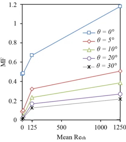
Figure 7 indicates the influences of the inclined angle (θ) on the flow distribution uniformity of the
289
ladder circuit, under different inlet velocity conditions. For a certain inclined angle, the flow
290
maldistribution increases with increasing inlet velocity, as already reported above. For a same inlet
291
velocity, larger inclined angle leads to more uniform flow distribution. However, the improvement
292
becomes less and less notable when θ value increases. These results are in accordance with those of
293
Pan et al. (2009), who reported that for symmetrical manifold structures velocity distribution becomes
294
more uniform with larger radius of inlet/outlet.
295
16
296
Figure 7. Influences of inclined angle (θ) on the flow distribution uniformity (MF) under different inlet velocity
297
conditions
298
299
4.2. Influence of the number of mini-channels
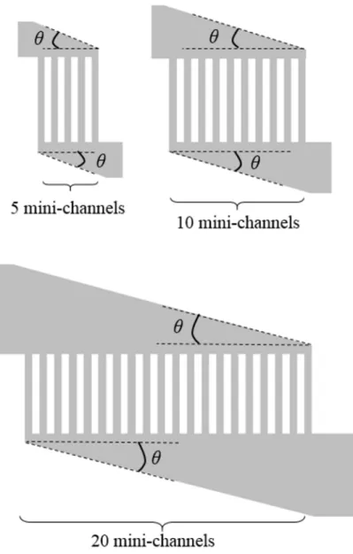
300
3D-CFD simulations were realized on Z-type ladder circuit with number of mini-channels of 5, 10 and
301
20, while the inclined angle of the distributor/collector pipes was fixed at 30°, as shown in Figure 8.
302
This is for the purpose of highlighting the influence of the number of mini-channels on the flow
303
distribution uniformity.
304
17
305
Figure 8. Geometries of ladder circuit tested with different number of mini-channels in parallel
306
307
Figure 9 shows the evolution of maldistribution factor (MF) as a function of the number of
mini-308
channels under four inlet velocity conditions studied. It may be observed that the difference on the
309
flow distribution uniformity for different N cases is relatively very small under low inlet velocity
310
conditions (e.g. Uin<1.25×10⁻² m.s-1; mean Rech=1.25×101). However, the value of MF increases
311
rapidly with increasing N number under high velocity conditions. For a inlet velocity Uin=1.25 m.s-1
312
(mean Rech=1.25×10³), the value of the MF increases from 0.100 for 5 channels case, to 0.217 for 10
313
channels case, and finally reaches 0.229 for 20 channels case. Generally speaking, it will be easier to
314
achieve uniform flow distribution when fewer sub-streams should be formed (small N).
315
18
316
Figure 9. Influences of the number of parallel channels (N) on the flow distribution uniformity (MF) under
317
different mean Rech conditions
318
319
5. CONCLUSION AND PERSPECTIVES
320
This paper presents a numerical study on the flow distribution characteristics of a Z-type ladder circuit
321
having 10 mini-channels in parallel. The validity and the effective range of the discrete stairway model
322
and the continuous tapered model for the design of distributor/collector pipes are discussed. The
323
effects of inclined angle and the number of parallel mini-channels on the distribution uniformity are
324
also analyzed. Based on the results presented above, the following conclusions may be reached.
325
• The discrete stairway model could provide relatively uniform flow distribution under low
326
flow-rate conditions (e.g. Uin<1.25×10⁻² m.s-1; mean Rech<1.25×101). For higher flow-rate
327
conditions, significant flow maldistribution seems inevitable.
328
• The continuous tapered model by linearizing the stairways may provide comparable flow
329
distribution uniformity regarding the discrete stairway model, but may be more favorable in
330
terms of lower pressure loss under higher flow-rate conditions.
331
19
• Increasing the inclined angle and decreasing the number of parallel channels are favorable for
332
more uniform flow distribution. However, the compactness of the network may then be lost.
333
It should be noted that both models could provide relatively uniform flow distribution under very low
334
flow-rate conditions. The potential applications could be for fuel cells where the flow velocity in
335
parallel channel is small, with the aim of process intensification. Another direction of application is to
336
construct a multi-scale fluidic network such as shown in Figure 1a, so that the working load for each
337
elemental Z-type circuit could be relatively small.
338
Our ongoing works are focused on the development of more appropriate scaling relations and
339
evolutionary algorithms (Wang et al., 2010; 2014; Luo et al., 2015) for more subtle modifications of
340
the distributor/collector shape, in order to reach uniform flow distribution with small increase of
341
pressure loss. Numerical and experimental investigations on the hydraulic and thermal characteristics
342
of a multi-scale ladder network are also the directions of our future work.
343
344
ACKNOWLEDGEMENT
345
The authors would like to thank the “Region Pays de la Loire” for the project “Nouvelle équipe de
346
recherche” and its financial support to the PhD study of M. Cyril Pistoresi.
347
348
NOMENCLATURE
349
Dh Hydraulic diameter [m]350
e Thickness of the fluidic network [m]
351
q Volume flow-rate [m3.s-1]
352
q
Mean flow rate among mini-channels [m3.s-1]353
f Friction factor [-]
354
F Form factor [-]
355
F External body force [kg.m.s-²]
356
g Gravitational acceleration [m.s-²]
20
I Unit tensor [-]
358
lx Space between two mini-channels [m]
359
L Length [m]
360
MF Maldistribution factor [-]
361
N Number of parallel mini-channels [-]
362
p Static pressure [Pa]
363
R Hydraulic resistance [Pa.s.m-3]
364
Re Reynolds number [-]
365
u Velocity [m.s-1]
366
Uin Velocity at the inlet of the network [m.s-1]
367
w Width [m]368
369
Greek symbols370
Δp Pressure loss [Pa]
371
θ Angle of Distributor/Collector pipes [°]
372
µ Viscosity [kg.m-1.s-1]
373
Stress tensor [-]
374
ρ Density of the fluid [kg.m-3]
375
σ Relative flow-rate deviation [-]
376
377
Subscripts378
c Collector pipe379
ch Mini-channel380
d Distributor pipe381
in Inlet382
k Channel index383
out Outlet384
385
21
REFERENCES
386
Al-Rawashdeh, M., Yu, F., Nijhuis, T.A., Rebrov, E.V., Hessel, V., Schouten, J.C., 2012,
Numbered-387
up gas–liquid micro/milli channels reactor with modular flow distributor, Chemical Engineering
388
Journal, 207–208, 645-655
389
Anxionnaz, Z., Cabassud, M., Gourdon, C., Tochon, P., 2008, Heat exchanger/reactors (HEX
390
reactors): Concepts, technologies: State-of-the-art, Chemical Engineering and Processing: Process
391
Intensification, 47, 2029-2050
392
Cho, E.S., Choi, J.W., Yoon, J.S., Kim, M.S., 2010, Modeling and simulation on the mass flow
393
distribuion in microchannel heat sinks with non-uniform heat flux conditions, International
394
journal of Heat and Mass Transfer, 53, 1341-1348
395
Charpentier J.C., 2005, Process intensification by miniaturization, Chemical Engineering Technology,
396
28, 255-258
397
Commenge, J.-M., Falk, L., 2014, Methodological framework for choice of intensified equipment and
398
development of innovative technologies, Chemical Engineering and Processing: Process
399
Intensification, 84, 109-127
400
Commenge, J.-M., Falk, L., Corriou, J.P., Matlosz, M., 2002, Optimal design for flow uniformity in
401
microchannel reactors, AIChE Journal, 48 345-358
402
Commenge, J.-M., Saber, M., Falk, L., 2011, Methodology for multi-scale design of isothermal
403
laminar flow networks, Chemical Engineering Journal, 173, 541-551
404
Fan, Y., Luo, L., 2008, Recent applications of advances in microchannel heat exchangers and
multi-405
scale design optimization, Heat Transfer Engineering, 29, 461-474
406
Fan, Y., Boichot, R., Goldin, T., Luo, L., 2008, Flow distribution property of the constructal
407
distributor and heat transfer intensification in a mini heat exchanger, AIChE Journal, 54,
2796-408
2808.
409
Guo, X., Fan, Y., Luo, L., 2013, Mixing performance assessment of a multi-channel mini heat
410
exchanger reactor with arborescent distributor and collector, Chemical Engineering Journal, 227,
411
116-127
412
22
Guo, X., Fan, Y., Luo, L., 2014, Multi-channel heat exchanger-reactor using arborescent distributors:
413
A characterization study of fluid distribution, heat exchange performance and exothermic
414
reaction, Energy, 69, 728-741
415
Hessel, V., Löwe, H., Schönfeld, F., 2005, Micromixers-a review on passive and active mixing
416
principles, Chemical Engineering Science, 60, 2479-2501
417
Illg, T., Löb, P., Hessel, V., 2010, Flow chemistry using milli- and microstructured reactors-From
418
conventional to novel process windows, Bioorganic & Medicinal Chemistry, 18, 3707-3719
419
Jackson, J.M., Hupert, M.L., Soper, S.A., 2014, Discrete geometry optimization for reducing flow
420
non-uniformity, asymetry, and parasitic minor loss pressure drops in Z-type configurations of fuel
421
cells, Journal of Power Sources, 269, 274-283
422
Khan, M.G., Fartaj, A., 2011, A review on microchannel heat exchangers and potential applicaions,
423
International journal of energy research, 35, 553-582
424
Kim, S., Choi, E., Cho, Y.I., The effect of header shapes on the flow distribution in a manifold for
425
electronic packaging applications, International Communications in Heat and Mass Transfer, 22,
426
329-341
427
Luo, L., 2013, Heat & Mass Transfer Intensification and Shape Optimization: A Multi-scale
428
Approach, Springer.
429
Luo, L., Fan, Y., Tondeur, D., 2007. Heat exchanger: from micro to multi-scale design optimization,
430
International Journal of Energy Research, 31, 1266-1274
431
Luo, L., Wei, M., Fan, Y., Flamant, G., 2015, Heuristic shape of optimization of baffled fluid
432
distributor for uniform flow distribution, Chemical Engineering Science, 123, 542-556
433
Midoux, N., Tondeur, D., 2014, The theory of parallel channels manifolds (Ladder networks)
434
Revisited Part 1: Discrete mesoscopic modelling. The Canadian Journal of Chemical
435
Engineering, 92, 1798-1821.
436
Midoux, N., Tondeur, D., 2015, The theory of parallel channels manifolds (Ladder networks)
437
Revisited Part 2: Design for uniform cross-flow distribution. The Canadian Journal of Chemical
438
Engineering, 93, 121-140.
439
23
Pan, M., Tang, Y., Pan, L., Lu, L., 2008, Optimal design of complex manifold geometries for uniform
440
flow distribution between micochannels, Chemical Engineering Journal, 137, 339-346
441
Pan, M., Zeng, D., Tang, Y., Chen, D., 2009, CFD-based study of velocity distribution among multiple
442
parallel microchannels, Journal of Computers, 4, 1133-1138
443
Renault, C., Roche, J., Ciumag, M.R., Tzedakis, T., Colin, S., Serrano, K., Reynes, O., André-Barrès,
444
C., Winterton, P., 2012, Design and optimization of electrochemical microreactors for continuous
445
electrosynthesis, Journal of Applied Electrochemistry, 42, 667-677
446
Rebrov, E.V., Schouten, J.C., De Croon, M.H.J.M., 2011, Single-phase fluid flow distribution and heat
447
transfer in microstructured reactors. Chemical Engineering Science, 66, 1374-1393
448
Saber, M., Commenge, J.-M., Falk, L., 2009, Rapid design of channel multi-scale networks with
449
minimum flow maldistribution, Chemical Engineering and Processing: Process Intensification,
450
48, 723-733
451
Saber, M., Commenge, J.-M., Falk, L., 2010, Microreactor numbering-up in multi-scale networks for
452
industrial-scale applications: Impact of flow maldistribution on the reactor performances,
453
Chemical Engineering Science, 65, 372-379
454
Stankiewicz, A., Moulijn, J.A., 2002, Process Intensification, Industrial & Engineering Chemistry
455
Research, 41, 1920-1924
456
Sung, Y., 2006, Optimization of a fuel-cell manifold, Journal of Power Sources, 157, 395-400
457
Tondeur, D., Fan, Y., Commenge, J-M., Luo, L., 2011a, Flow and pressure distribution in linear
458
discrete “ladder-type” fluidic circuits: An analytical approach, Chemical Engineering Science, 66,
459
2568-2586
460
Tondeur, D., Fan, Y., Commenge, J-M., Luo, L., 2011b, Uniform flows in rectangular lattice
461
networks, Chemical Engineering Science, 66, 5301-5312
462
White, F.M., 2003, Fluid Mechanics, 5th Edition, McGraw-Hill.
463
Wang, L., Fan, Y., Luo, L., 2010, Heuristic optimality criterion algorithm for shape design of fluid
464
flow, Journal of Computational Physics, 229, 8031-8044
465
Wang, L., Fan, Y., Luo, L., 2014, Lattice Boltzmann method for shape optimization of fluid
466
distributor, Computers & Fluids, 94, 49-5