© Emna Ghazali, 2017
Mechanical performance of adhesively bonded repairs
in honeycomb composite sandwich structures
Thèse
Emna Ghazali
Doctorat en génie mécanique
Philosophiæ doctor (Ph. D.)
Mechanical Performance of Adhesively Bonded Repairs
in Honeycomb Composite Sandwich Structures
Thèse
Emna Ghazali
Sous la direction de :
Marie-Laure Dano, directrice de recherche
Augustin Gakwaya, codirecteur de recherche
iii
Résumé
En service, les pièces aéronautiques en matériaux composites et structures sandwiches subissent des dommages qui nécessitent des réparations. Les réparations par patch interne en biseau, en escalier ou par combinaison des deux offrent une excellente restauration de la résistance mécanique pour ces structures composites. Cependant, l’environnement de réparation peut se révéler être un défi de taille quant à leur mise en œuvre, au choix des
paramètres géométriques (angle de biseau, nombre de plis extra), à leur comportement mécanique sous différents chargements ainsi qu’à leur processus d’endommagement.
Cette thèse présente une étude expérimentale et numérique (éléments finis) du comportement mécanique de réparations par patch interne effectuées sur des structures avec des peaux en composites à renforts tissés fabriquées hors autoclave et âme en Nomex en nid d’abeille. Afin de déterminer l’effet de différents paramètres géométriques sur la résistance de la réparation et
de comprendre son comportement mécanique et son processus d’endommagement, une série de tests de caractérisation sous différents chargements (traction, compression, flexion) a été effectuée sur des structures sandwiches faite avec deux matériaux composites tissés pour la peau : soit du composite tissé taffetas (PW) ou satin de 8 (8HS)
Des simulations numériques ont été effectuées afin de prédire le comportement mécanique de la réparation. Cette étude numérique a été effectuée en plusieurs étapes. Un premier modèle
iv 2D qui suppose que la colle ait un comportement linéaire élastique a été développé et permet d’étudier la distribution des contraintes dans le joint de colle pour différentes configurations de
réparation rectangulaire. Ensuite, le modèle 2D est modifié pour tenir compte du comportement élastoplastique de la colle et ceci permet de prédire le comportement mécanique d’une réparation rectangulaire jusqu’à la rupture. Par la suite, un modèle 3D est développé pour
prédire le comportement de réparations circulaires sous des chargements de compression. Ce modèle tient compte de l’endommagement progressif des peaux en composite. Les résultats de
ces simulations numériques sont comparés par la suite aux mesures expérimentales. Les modèles par éléments finis, avec une loi de comportement élastoplastique pour le joint de colle, permettent une estimation adéquate de la résistance ainsi que de l’endommagement des structures sandwiches réparées. Une étude paramétrique a eu lieu afin d’étudier l’effet de différents paramètres géométriques sur la résistance de la réparation.
La mise en œuvre et la détermination de la performance mécanique des réparations par patch
interne des structures sandwiches est une tâche complexe avec de multiples paramètres de matériaux et de procédés. D’une manière générale, cette thèse contribue à une meilleure compréhension du comportement mécanique des structures sandwiches réparées et de leur processus d’endommagement. Les modèles par éléments finis développés dans ces travaux ont
été validés expérimentalement et des simulations paramétriques ont contribué à une meilleure compréhension de l’influence des différents paramètres géométriques sur la résistance de la
v
Mots-clés : Structures sandwiches, Réparation collée, Simulation numérique, hors-autoclave,
vi
Abstract
In service, aeronautical components made of composite materials and sandwich structures are subject to type of damages that require repairs. Adhesively bonded repairs (scarf-scarf, step-step or scarf-step-step) offer an excellent mechanical strength recovery for these composite structures. However, the repair environment can be a significant challenge in terms of the choice of geometrical parameters (scarf angle, addition of an overply), damage process parameters and mechanical behavior under different loads.
This thesis presents both experimental and numerical investigations of the mechanical behavior of internal patch repairs carried-out on Nomex honeycomb composite sandwich structures. The skins use an out-of- autoclave woven fabric made of carbon-epoxy composite materials. In order to determine the effect of different geometric parameters on the resistance of the internal patch repair and to better understand its mechanical behavior and damage processes, a series of mechanical tests under different loads (tensile, compression, bending) is conducted on the repaired sandwich panels made with either plain weave or 8 harness satin textile composites. Numerical simulations were carried out, in several stages, in order to determine the mechanical behavior of the repair. First, a 2D model that assumes a linear elastic behavior of the adhesive film was developed. This simple model allows to study the distribution of the stresses in the adhesive joint for different configurations of rectangular patch repair. Then, the 2D model is modified in order to account for the elastoplastic behavior of the adhesive film. The latter allows to predict the mechanical behavior of a rectangular internal patch repair until rupture.
vii Subsequently, a 3D model is developed to predict the mechanical behavior of circular internal patch repairs under compressive loadings. This model takes into account the progressive damage and failure of the woven fabric skins. The results of these numerical simulations are validated by comparing them to experimental measurements. The finite element models that account for the elastoplastic behavior law for the adhesive joint allow predictions of the strength as well as the damage morphology of the repaired sandwich structures. A parametric study has also been conducted in order to determine the influence of the geometrical design parameters in the repair strength.
Processing and assessment of the mechanical performance of internal patch repairs on sandwich structures is a complex task with multiple material and process parameters. In general, this thesis contributes to a better understanding of the mechanical behavior of adhesively bonded repaired sandwich structures and their damage process. The finite element models developed in this work and validated experimentally have contributed through parametric numerical simulations to an economical better understanding of the influence of different geometric parameters on the strength and failure of internal patch repaired sandwich panels.
Keywords: Honeycomb composite sandwich structures, Bonded repair, Progressive damage,
viii
Table of content
Résumé ... iii
Abstract ... vi
Table of content ... viii
List of Tables ... xiii
List of Figures ... xvi
Nomenclature ... xxii
Acknowledgements ... xxvi
Avant-Propos ... xxvii
Introduction ... 1
Chapter 1.
Literature Review ... 8
1.1 A Review of Monolithic Composite Bonded Repair Design ... 8
1.1.1 Composite Bonded Joint Repairs ... 9
1.1.2 Analytical Methods ... 10
1.1.3 Finite Element Analysis Techniques ... 12
1.1.4 Failure Mechanisms of Composite Bonded Joint Repairs: Observations and Modeling Process ... 21
1.1.5 Review Summary ... 29
1.2 A Review of Honeycomb Sandwich Panel Bonded Repairs ... 29
1.2.1 Introduction ... 30
1.2.2 State-of-The-Art Review of Sandwich Panel Repairs ... 35
ix
Chapter 2.
Overview of the Problem and Research Focus ... 47
2.1 Rationale of the Thesis... 47
2.1.1 Assessment of the Mechanical Behavior of Honeycomb Sandwich Panels with Bonded Repairs by Experimental Testing ... 49
2.1.2 Development of Finite Element Models for Better Understanding and Accurate Prediction of the Mechanical Behavior and Failure Modes of the Repaired Sandwich Panels under Different Loadings ... 50
2.1.3 Validation of the Finite Element Models and Conduction of a Parametric Study 50 2.2 Methodology and Thesis Structure ... 51
2.2.1 Methodology ... 51
2.2.2 Chapters Presentation... 54
Chapter 3.
Mechanical Characterization and Finite Element Study of
Monolithic Facesheets and Honeycomb Core ... 56
3.1 Experimental Characterization of the Facesheet Materials ... 57
3.1.1 Materials Description and Specimens Manufacturing ... 57
3.1.2 Mechanical Testing of the Laminate Used for the Skins ... 58
3.2 Mechanical Characterization of the Honeycomb Nomex Core ... 65
3.2.1 Out-of-Plane Compressive Tests ... 66
3.2.2 In-Plane Tensile Tests ... 68
3.2.3 Nomex Tests Recapitulation ... 69
3.3 Analytical and Finite Element Studies of the Facesheets Mechanical Behavior ... 70
3.3.1 Classical Lamination Theory: Analytical Approach ... 71
3.3.2 Finite element Analyses ... 73
3.4 Conclusion ... 82
Chapter 4.
Article 1: Mechanical Performance of Repaired Sandwich Panels:
Experimental Characterization and Finite Element Modelling ... 83
x
4.2 Experimental Work ... 88
4.2.1 Repaired Sandwich Specimen Preparation ... 88
4.2.2 Tensile tests procedure ... 91
4.2.3 Experimental Results ... 92
4.2.4 Damage Mode and Fractography Studies ... 94
4.3 Numerical Simulation ... 98
4.3.1 Model Description ... 98
4.3.2 Linear Elastic Numerical Model ... 100
4.3.3 Non-linear Elastic Plastic Model ... 102
4.3.4 Numerical Results and Discussion... 106
4.4 Conclusions ... 108
Chapter 5.
Article 2: Parametric Study of Stepped-Scarf Bonded Joints in
Repaired Honeycomb Sandwich Composite Panels ... 109
5.1 Introduction ... 110
5.2 Finite Element Model Description ... 114
5.2.1 Model Geometry and Material System Description ... 114
5.2.2 Boundary Conditions and Finite Element Mesh Details... 116
5.2.3 Materials Models ... 117
5.3 Parametric Study ... 118
5.4 Results ... 120
5.5 Discussion ... 131
5.6 Conclusions ... 135
Chapter 6.
Article 3: Evaluation of the mechanical performance of repaired
composite sandwich structure using different mechanical tests ... 138
6.1 Introduction ... 139
6.2 Experimental Work ... 143
6.2.1 Materials ... 143
xi
6.2.3 Specimen Preparation and Test Procedure ... 144
6.2.4 Results and Discussion ... 151
6.3 Finite Element Analysis ... 161
6.3.1 Model Description ... 161
6.3.2 Model Results ... 164
6.4 Conclusion ... 166
Chapter 7.
Article 4: Experimental and Numerical Studies of Stepped-Scarf
Circular Repair in Composite Sandwich Panels ... 169
7.1 Introduction ... 171
7.2 Experimental Work ... 175
7.2.1 Objective and Methodology ... 175
7.2.2 Specimen Preparation ... 176
7.2.3 Edgewise Compressive Tests ... 179
7.2.4 Four-Point Bend tests ... 181
7.3 Numerical Simulation ... 185
7.3.1 Finite Element Model Description ... 185
7.3.2 Failure Criteria and Damage Evolution ... 188
7.3.3 Results and Discussions: Edgewise Compressive Tests ... 191
7.4 Conclusion ... 195
Chapter 8.
Conclusions and Perspectives ... 197
8.1 Thesis Conclusions ... 197
8.2 Thesis Original Contributions ... 201
8.3 Recommendations for Future Work... 204
References ... 206
Appendix A. Mechanical performance of the 8HS honeycomb sandwich panels
... 212
xii
Specimens Dimensions and Test Set-up ... 213
Test Results for the Pristine 8HS Honeycomb Sandwich Panels ... 214
Test Results for the 2D Repaired 8HS Honeycomb Sandwich Panels ... 214
Strength Recovery of the 3°-Repaired Sandwich Panels ... 217
A.2 Compressive Tests on 8HS Honeycomb Sandwich Panels ... 218
Compressive Tests on Pristine and 2D Repaired Honeycomb Panels ... 219
A.2.1.1 Compressive Tests on the Pristine 8HS Honeycomb Sandwich Panels ... 219
A.2.1.2 Compressive Tests on the 2D Repaired 8HS Honeycomb Sandwich Panels .... 221
A.2.1.3 Recapitulation and Strength Recovery of the 8HS Repaired Sandwich Panels. 222 Compressive Tests on 3D Repaired and Open-Hole 8HS Honeycomb Panels . 224 A.3 Flexure Tests on Pristine and 2D Repaired 8HS Honeycomb Sandwich Panels ... 227
Long-Beam Flexure Tests ... 227
Tests Results and Interpretation ... 229
xiii
List of Tables
Table 1-1 Parameters effects on the peel and shear stresses [21] ... 17Table 1-2 Issues and aspects studied in the literature for composite bonded repairs ... 29
Table 1-3 Structural efficiency of sandwich panels in terms of weight [41] ... 31
Table 1-4 Sandwich panels component materials used in the literature ... 45
Table 1-5 Repair configuration, process and cure methods for sandwich panel repairs used in the literature ... 46
Table 1-6 Mechanical characterization and non-destructive inspection of sandwich panel repairs used in the literature ... 46
Table 1-7 Finite element model types used in the literature for sandwich honeycomb panels ... 46
Table 3-1 Materials properties from Cytec [59] ... 57
Table 3-2 Statical analysis - tensile tests ... 64
Table 3-3 Statical analysis - compressive tests ... 65
Table 3-4 Mechanical properties for the ECA-R Nomex core (from [63])... 66
Table 3-5 Compressive mechanical properties for the over-expanded Nomex core ... 67
Table 3-6 Tensile elastic modulus in the L-and W-directions for the over-expanded Nomex core ... 69
Table 3-7 Mechanical properties of the over-expanded Nomex honeycomb core (ECA-R 4.8 64) ... 70
Table 3-8 Composite materials elastic properties ... 72
Table 3-9 Comparison between analytical and experimental results ... 73
Table 3-10 Predicted and measured elastic modulus of the quasi-isotropic laminate ... 77
Table 3-11 Mechanical properties used for the PW composite material ... 80
Table 3-12 Comparison between the experimental data and the finite element prediction 80 Table 4-1 Test matrix. ... 92
xiv
Table 4-2 Comparison of the ultimate stress between the sandwich skin and a [(+45/-45)/ (0/90)/ (-45/+45)/ (90/0)]2s quasi-isotropic laminate made from the same PW prepreg [74] .. 95
Table 4-3 Mechanical properties of the plain weave material. ... 99
Table 4-4 Mechanical properties of the FM300-2M adhesivea. ... 99
Table 4-5 Mechanical properties of the Nomex honeycomb core ... 100
Table 4-6 Stiffness prediction of pristine panels. ... 101
Table 4-7 Hardening data input. ... 106
Table 5-1 Mechanical properties of the plain weave composite material ... 117
Table 5-2 Mechanical properties of the FM300-2M adhesive ... 118
Table 5-3 Mechanical properties of the Nomex honeycomb core ... 118
Table 5-4 Parametric model details ... 119
Table 5-5 Baseline model values... 120
Table 6-1 Test matrix for different experimental tests ... 144
Table 6-2 Summary of the compressive test results ... 154
Table 6-3 Summary of the tensile test results ... 156
Table 6-4 Summary of the flexure test results ... 157
Table 6-5 Elastic material properties of the plain weave carbon-epoxy ply ... 163
Table 6-6 Mechanical properties of the over-expanded Nomex honeycomb core (ECA-R 4.8 64) ... 163
Table 6-7 Mechanical properties of the hexagonal Nomex honeycomb core (ECA 3.2 96) ... ... 164
Table 6-8 Mechanical properties of the FM300-2M adhesive film ... 164
Table 7-1 Mechanical properties of the plain weave composite material (CYCOM 5320 T650 PW). ... 178
Table 7-2 Mechanical properties of the over-expanded Nomex honeycomb core (ECA-R 4.8 64). ... 178
Table 7-3 Mechanical properties of the hexagonal Nomex honeycomb core (ECA 3.2 96) ... ... 179
xv Table 7-5 Test matrix. ... 181 Table 7-6 Test results for different sandwich panels configuration. ... 183
xvi
List of Figures
Figure 1-1 Common configurations of bonded repair joints, 2D geometries ... 10Figure 1-2 Failure mechanisms of a bonded joint ... 22
Figure 1-3 A tension-loaded 2D scarf joint used in the literature [31] ... 22
Figure 1-4 Failure morphology of a low scarf repair joint angle under tensile load [31] . 24 Figure 1-5 Failure paths observed in the static tensile 2°-scarf repaired joints under different environmental conditions [16] ... 24
Figure 1-6 Failure morphology of a circular patch repair: (a) top surface (b) bottom surface (adapted from [30]) ... 25
Figure 1-7 Cohesive zone models’ presentation: (a) triangular law, (b) trapezoidal law [20]. ... 27
Figure 1-8 Nomenclature used to describe the sandwich panel geometric characteristics 31 Figure 1-9 Different failure modes of a sandwich panel [43]. ... 35
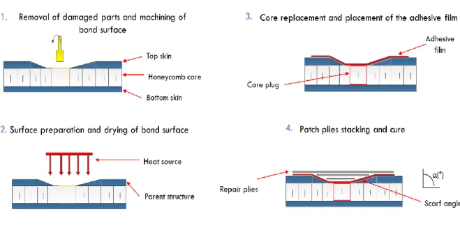
Figure 1-10 Typical scarf-type repair procedure of a honeycomb composite sandwich panel ... 36
Figure 1-11 Scarf-type repair patches on honeycomb sandwich panel ... 38
Figure 2-1 Repair configurations in sandwich honeycomb panels ... 49
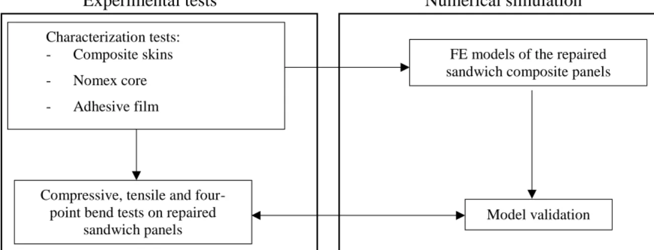
Figure 2-2 Flowchart of the research methodology ... 51
Figure 2-3 Longitudinal-cross section modeled with 2D model ... 53
Figure 2-4 Circular 3D model geometry ... 53
Figure 3-1 Fiber architecture pattern for a) an 8HS fabric and b) a PW fabric (adapted from[60]) ... 57
Figure 3-2 Vacuum bag arrangement and cure cycle used for the quasi-isotropic laminates ... 59
Figure 3-3 Micrographs of PW and 8HS laminate cross-sections after cure ... 60
xvii
Figure 3-5 Typical stress-strain curve for a [(+45/-45)/(0/90)/(-45/+45)/(90/0)]2s PW specimen tested in tension ... 62
Figure 3-6 Typical stress-strain curve for a [(+45/-45)/(0/90)/(-45/+45)/(90/0)]s 8HS specimen tested in tension ... 62
Figure 3-7 Typical failure for specimens tested in tension in the x- and y-directions ... 63
Figure 3-8 Typical stress-strain curve for a [(+45/-45)/(0/90)/(-45/+45)/(90/0)]2s PW specimen tested in compression in the x-direction ... 63
Figure 3-9 Typical stress-strain curve for a [(+45/-45)/(0/90)/(-45/+45)/(90/0)]s 8HS specimens tested in compression in the x-direction ... 63
Figure 3-10 Typical failure mode for specimens tested in compression in the x-direction 64 Figure 3-11 Nomenclature and dimensions of a ECA-R unit cell (4.8 mm) ... 66
Figure 3-12 Compressive test set-up ... 67
Figure 3-13 Typical compressive stress-strain curve ... 67
Figure 3-14 Specimen configuration and tensile test set-up ... 68
Figure 3-15 Typical tensile stress-strain curves in the ribbon (L) and transverse (W) directions ... 70
Figure 3-16 Geometry of studied and simplified specimen (not to scale) ... 74
Figure 3-17 Changes in Stiffness matrix to respect modelling convention ... 75
Figure 3-18 Boundary conditions for the 2D laminate tensile test (not to scale) ... 75
Figure 3-19 Comparison of stress-strain curves between the experiment and the finite element model for a [(+45/-45)/(0/90)/(-45/+45)/(90/0)]2s PW tested in tension in the x-direction ... 81
Figure 3-20 Comparison of stress-strain curves between the experiment and the finite element model for a [(+45/-45)/(0/90)/(-45/+45)/(90/0)]2s PW tested in compression in the x-direction ... 81
Figure 4-1 Parent panel dimension (not to scale). ... 89
Figure 4-2 1D scarf/step repair configuration (not to scale). ... 91
xviii
Figure 4-4 Axial load-strain curves obtained for the pristine and 3-repaired sandwich specimens (strains measured by DIC on the tool facesheet). ... 93
Figure 4-5 Comparison of the axial load-strain curves obtained on both facesheets of the sandwich specimens. ... 94
Figure 4-6 Tensile failure load of the pristine and repaired sandwich specimens... 94
Figure 4-7 Failure mode of pristine panels. ... 96
Figure 4-8 Failure mode for the 3°-repaired sandwich panels. ... 96
Figure 4-9 Micrograph of the cross-section of the (a) pristine specimen, (b) repaired sandwich specimen before testing. ... 97
Figure 4-10 Micrograph of the 3°-repaired sandwich specimen cross-section after failure.... ... 97
Figure 4-11 Description of the boundary conditions. ... 99
Figure 4-12 Line and local coordinate system used to extract peel and shear stresses ... 101
Figure 4-13 Shear stress distribution along the bondline. ... 102
Figure 4-14 Peel stress distribution along the bondline... 102
Figure 4-15 Finite element prediction versus experiment results for the 3°-repaired sandwich panels. ... 107
Figure 4-16 Failure load and efficiency (η= 𝑃𝑟𝑒𝑝𝑎𝑖𝑟𝑓𝑃𝑢𝑛𝑑𝑎𝑚𝑎𝑔𝑒𝑑𝑓𝑥100) for different scarf-step angles. ... 107
Figure 5-1 Configuration of the double scarf-stepped repair joint (not to scale). ... 115
Figure 5-2 Symmetric cross-section of the double scarf-stepped repaired sandwich panel (not to scale). ... 116
Figure 5-3 Line and local coordinate system to extract peel and shear stresses in the adhesive joint. ... 119
Figure 5-4 Shear and peel stress distributions along the adhesive bondline for different scarf angles. ... 121
Figure 5-5 Repair failure stress for different scarf angles. ... 122
Figure 5-6 Shear and peel stress distributions along the adhesive bondline as a function overlap length Lo (3°-4-ply skin model). ... 126
xix
Figure 5-7 Determination of the minimal overply overlap length ... 127
Figure 5-8 Repair strength prediction as function of the overlap length, Lo (3°-4-ply skin model). ... 127
Figure 5-9 Failure morphology of a specimen with an overlap length, Lo=10. ... 127
Figure 5-10 Shear and peel stress distributions along the adhesive bondline as a function of number of skin plies, N (α=3o)... 130
Figure 5-11 Repair strength prediction as function of the number of skin plies, N (α=3°). .... ... 131
Figure 5-12 Map of the failure stress as a function of the scarf angle and number of plies, N. ... 134
Figure 5-13 Variation of the failure stress as a function of the overply and number of skin plies, N (α=3°). ... 134
Figure 6-1 Parent panel dimension (not to scale) ... 145
Figure 6-2 2D stepped-scarf repair configuration ... 145
Figure 6-3 Specimen geometry (not to scale) ... 147
Figure 6-4 CAI fixture system used for the edgewise compressive tests ... 147
Figure 6-5 Location of strain gages (not to scale) ... 148
Figure 6-6 Micrograph of the repair cross-section before testing ... 148
Figure 6-7 Tensile test set-up. ... 149
Figure 6-8 Four-point bend test fixture and specimen configurations (not to scale) ... 150
Figure 6-9 Typical force versus strain curves for pristine and 3°-repaired sandwich specimens tested in compression ... 152
Figure 6-10 Force-strain curves obtained using different strain measuring instruments for pristine and 3°-repaired sandwich specimens tested in compression ... 153
Figure 6-11 DIC measurement: out-of-plane displacement of 3°-repaired sandwich specimen tested in compression at failure ... 153
Figure 6-12 Micrograph of the repair cross-section after failure of 3°-repaired sandwich specimen tested in compression ... 154
xx
Figure 6-13 Typical axial load-strain curves for the pristine and 3°-repaired sandwich specimens tested under tension ... 156
Figure 6-14 Typical stress versus strain curves for pristine and 3°-repaired sandwich beams tested under four-point bending ... 157
Figure 6-15 . Failure mode of a 3°-repaired sandwich beam tested under four-point bending (repair in tension) ... 157
Figure 6-16 Comparison of the failure stress of the pristine panels obtained from different loading types. ... 160
Figure 6-17 Comparison of the failure stress of the 3°-repaired panels obtained from different loading types. ... 160
Figure 6-18 Studied longitudinal cross-section of the repaired specimens ... 162
Figure 6-19 Model geometry and boundary conditions for the four-point bend test ... 163
Figure 6-20 Mesh details of the adhesive bondline ... 163
Figure 6-21 Numerical predictions versus experimental results for 3°-repaired sandwich specimens under different load cases. ... 165
Figure 6-22 Deformation and failure mode for a 3°-repaired beam tested under four-point bending (repair in compression) ... 166
Figure 7-1 Stepped-scarf repair zone cross-section (not to scale). ... 178
Figure 7-2 Compressive test fixture and strain gages location. ... 181
Figure 7-3 Specimens configuration and four-point bending test fixture. ... 183
Figure 7-4 Stress-strain curves for the pristine sandwich beams. ... 184
Figure 7-5 Stress-strain curves for the 3° repaired sandwich beams. ... 184
Figure 7-6 Failure morphology of the pristine and the 3°-repaired sandwich beams under four-point bending. ... 185
Figure 7-7 Failure stress of the pristine and 3° repaired panels under four-point bending. .. ... 185
Figure 7-8 Mesh details of the honeycomb sandwich panels. ... 187
Figure 7-9 Mesh refinement details of the 3°-repaired panel ... 188
xxi Figure 7-11 Finite element prediction versus experiment results for composite sandwich panels ... 193 Figure 7-12 Failure mode for the tested composite sandwich panels. ... 194 Figure 7-13 Predicted failure morphology for the three panel configurations. ... 194
xxii
Nomenclature
List of Latin symbols
Loverlap: Overlap Length
L: Total Length of the Specimen
F: Applied Force A: Section Area E: Elastic Modulus G: Shear Modulus S: Standard Deviation N: Number of Plies
t: Total Thickness of the Specimen
w: Total Width of the Specimen
tf: Thickness of the Facesheet
ta: Thickness of the Adhesive Film
tp: Thickness of the Ply
xxiii
List of Greek symbols
σi: Stress (i=x, y)
ν: Poisson’s ratio
α: Scarf Angle
ρ: Density
List of acronyms
RTM: Resin Transfer Molding
C.V: Coefficient of Variation
CLT: Classical Lamination Theory
CFRP: Carbon Fiber Reinforced Plastic
U.D: Unidirectional
RT: Room Temperature
FE: Finite element
OOA: Out-of-Autoclave
PW: Plain Weave
8HS: Eight Harness Satin
DIC: Digital Image Correlation
xxiv TAST: Thick Adherend Shear Test
CAI: Compression after Impact
S8R: Eight-Node Reduced Integration Shell Elements
AGARD: Advisory Group for Aerospace Research & Development
xxv
xxvi
Acknowledgements
First and foremost, I would like to express my deepest gratitude to Professors Marie-Laure Dano and Augustin Gakwaya, my research supervisors, for providing me with continuous opportunities to grow as a young researcher. Their constant support and constructive advices made these years at Laval University rich in terms of technical learning and personal development. Thank you for all your support Marie-Laure and Augustin.
Many thanks to Charles-Olivier Amyot for his time and help to ensure the manufacturing and testing of the sandwich panels. Many thanks also to Mathieu Pouliot and Jonathan Guy-Larose.
I am very thankful to the industrial partners for sharing their expertise in composite repairs, especially David Wilson, Hasan Salek, Isabelle Paris from Bombardier Aerospace and Étienne Bélanger from L3-Mas. Thank you for reviewing my papers.
This project was made possible by the financial support, materials provision, and access to equipment from the Consortium for Research and Innovation in Aerospace in Quebec (CRIAQ); the Natural Science and Engineering Research Council (NSERC), the National Research Council Canada (NRC/CNRC), Université Laval, École Polytechnique de Montréal McGill University, Bombardier Aerospace and L-3 MAS.
xxvii
Avant-Propos
Ce travail présente une thèse par articles comprenant quatre articles qui sont soit publié, accepté pour publication ou soumis. Ces articles sont :
Article 1 intitulé “Mechanical performance of repaired sandwich panels: Experimental
Characterisation and finite element modeling’’ a été soumis en décembre 2016 au journal Sandwich Structures and Materials et publié en mai 2017. L’auteur principal
pour cet article est Emna Ghazali et les co-auteurs sont : Marie-Laure Dano, Augustin Gakwaya et Charles-Olivier Amyot.
Article 2 intitulé “Parametric study of stepped-scarf bonded joints in repaired honeycomb sandwich composite panels’’ a été soumis au Journal of Adhesion en
novembre 2017. L’auteur principal pour cet article est Emna Ghazali et les co-auteurs sont: Marie-Laure Dano et Augustin Gakwaya.
Article 3 intitulé “Evaluation of the mechanical performance of repaired composite
sandwich structure using different mechanical tests’’ a été soumis au Journal of Adhesion & Adhesives en décembre 2017. L’auteur principal pour cet article est Emna Ghazali et les co-auteurs sont: Marie-Laure Dano, Augustin Gakwaya et Charles-Olivier Amyot.
Article 4 intitulé “Experimental and numerical studies of stepped-scarf circular repairs
xxviii Adhesives et accepté pour publication avec corrections mineures en octobre 2017. L’auteur principal pour cet article est Emna Ghazali les co-auteurs sont: Marie-Laure
Dano, Augustin Gakwaya et Charles-Olivier Amyot.
Les versions intégrées dans cette thèse sont les versions publiées ou soumises des articles.
La candidate a effectué les travaux expérimentaux et numériques présentés dans ces articles à quelques exceptions près indiqués ci-dessous :
Article 1: Mathieu Pouliot, étudiant stagiaire, a aidé à la préparation des éprouvettes. Charles-Olivier Amyot, professionnel de recherche a aidé dans les différents tests mécaniques.
Article 3 : Jonathan Guy La rose et Éloïse Dol, étudiants stagiaires ont aidé à la fabrication et aux tests mécaniques de la flexion 4-points avec une étroite participation de Charles-Olivier Amyot pour la conception du montage de flexion.
1
Introduction
Although advanced composite materials and especially honeycomb sandwich structures have been traditionally used in aerospace applications, they have gained more popularity in high-performance structural design in the last years. The diversity of the types of reinforcements (carbon, glass, graphite, etc.), resins and associated manufacturing processes (autoclave, RTM, out-of-autoclave, etc.) shows that the use of these materials (monolithic or sandwich structures) is expanding. Their success is due to the various advantages they can offer compared to metals: good fatigue performance, good resistance to corrosion, high-strength-to-weight ratio (light-weight-to-stiffness ratio) etc. However, independent of the airframes materials, structural damage inevitably occurs while in service as a consequence of accidental contact with ground service vehicle, in-flight hailstones, bird strikes or lightning strikes that may cause critical damages. Hence following reference [1], “the maintenance and repair of these components are
vital to ensure that the performance of these composite components remain the same as they were initially designed”( p.919). The damage extent determines whether the component needs
to be repaired or replaced. Moreover, because of time constraint issues, repairs must be performed as quickly as possible so that the aircraft can be returned into service as soon as possible. After inspection, maintenance procedure will depend on damage extent. If damage is minor (i.e., it does not affect the structural integrity of the part), then it is classified as an allowable damage and only requires a cosmetic repair. However, when damage exceeds the
2 allowable damage size, a structural repair is needed in order to restore the initial carrying capacities of the structure. Finally, for damage larger than the repairable damage limit size, if an appropriate repair cannot be substantiated, the component has to be replaced. So, one of the main challenges facing the aerospace industry with composite materials (monolithic and sandwich) is structural repair. With the increase of the number of aircraft primary structure components made of composite materials (either monolithic or honeycomb sandwich), it has become necessary to develop repair methods that will restore the component’s original design
strength without compromising its structural integrity [2]. It is therefore essential to have robust, reliable and reproducible procedures related to structural repair to restore the strength and integrity of damaged composite and sandwich structures. However, with existing repair technologies, structural repairs present several scientific challenges, especially with primary structures. To repair damaged structural components, two main methods are typically considered: bolted repairs and bonded repairs, and bonded repairs are divided into external bonded repair patches and scarf-type bonded repair patches. Bolted repairs increase significantly the weight of the component. Also, fasteners offer non-negligible stress concentrations around the bolt holes. According to [1], depending on the type of damage sustained, “different repair techniques have been developed to address each specific case’’ (p.900-904). To repair a wide range of cracks or damage to aircraft components and structures, externally bonded composite repair patches have been shown to be effective [3]. They were originally used for the repair of military aircraft, but have since been used on civil aircraft. Traditionally, repairs on metallic aircraft structures were performed using bolted joints,
3 however bonded repairs are the most common repair technique used with composite materials [4]. The advantages of utilizing bonded composite repairs [5] include:
High resistance to damage by cyclic loads, immunity to corrosion, and high formability that
allows easy forming into complex shapes.
Compared to bolted repairs, bonded repairs offer an alternative repair method that can
effectively reduce the introduction of unwanted stress risers caused by the fasteners used in a bolted repair, which can severely hinder the performances of the repair [6].
Another disadvantage of using a bolted repair is the likelihood of damaging the surrounding
material while drilling fastener holes.
Composite materials can delaminate from improper hole drilling procedures and from excessive heat generated from the hole drilling.
Hence to reduce the possibility of thermal delamination, diamond tipped cutting wheels are utilized in the surface grinding equipment, together with coolant that is used during the partitioning process.
Due to the advantages from utilizing bonded repairs, the Composite Aircraft Field Repair Method (CAFRM) is being developed as a bonded field repair. There are two types of bonded repairs commonly used to repair structural damage.
The first type of bonded repair is an external repair patch that can recover most of the component’s strength. It has the advantage of being easy to perform and does not require a
4 large amount of time to complete [6]. This makes it a good candidate for a field repair method.
The effectiveness of bonded external patch repairs depends on several design parameters that play a vital role. These include in particular, the patch size, patch shape, materials used, patch taper, patch fiber orientation, and curing temperatures of the patch [6]. In order to ensure that the stresses induced into the adhesives are within the design limits of both the material and the operating envelope of the aircraft structure, care must be taken during the design phase of these patches.
Most of these parameters are defined by the manufacturer’s Structural Repair Manual (SRM) for the specific aircraft structure being repaired.
The second type of bonded repair is a scarf-type patch. Compared to external patches,
because of the matching of the repair plies to the plies in the original structures, scarf-type patches provide higher stiffness. Moreover, the amount of stress risers in a scarf-type patch repairs are also lower than in external patch repairs.
By matching the neutral axis of the repair patch to the original structure, scarf-type patch repairs are more efficient in load transfer due to the reduced load eccentricity [7].
However, aside from the advantages a scarf-type patch repair has over an external patch repair, scarf-type patch repairs have also some disadvantages:
5 They require a large amount of original material to be removed in order to
maintain a small taper angle.
The placement of the repair plies must be accurately laid up in the repair joint to the same orientation and order as the original structure. “The accurate
placement of repair plies can be very challenging and the risks of errors are very high” [1].
The performance of the scarf-type patch can greatly depend on the curing method utilized to cure the repair. “Repairs cured using different methods compared to the original structure can greatly affect the strength of the repairs and cause a mismatch between the original structure and the repair patch’’.
Finally, the adhesives flow under the scarf-type repair patch during curing can be hard to control, causing the adhesives to accumulate in the bottom of the patch thus creating a non-uniform bondline.
Due to all these characteristics, a scarf-type repair patch can be:
“Very time consuming and highly dependent on the skill level of the maintenance technician due to the requirement of accurately removing original materials from the structure and of precisely replacing the removed materials with new composite materials. Scarf-type repair patch can thus hardly be considered as candidate for bonded field repair’’.
6 With the above challenges in mind, the authors in [7] then recommend that: “if a scarf type
repair is to be performed on a part that is not considered to be a lightly loaded component, the scarf-type patch repair should be performed at a repair facility where equipment such as an autoclave is available in order to produce repaired aircraft parts that have the same part strength as the original structure”.
In this project, we are concerned with out-of-autoclave composites, and we will try to develop bonded repair techniques appropriate for out-of-autoclave (OOA) woven composites with the ultimate goal of setting up a field repair technology for this kind of composites.
This thesis research work is part of the CRIAQ COMP-507 project, which brings together several partners from industry (BA, L-3Mas), from academics (Laval, McGill, Polytechnique) and from government Laboratory (NRC-CNRC) for the development of reliable repair methods and analytical and numerical tools for the repair of composite structures and primary sandwich panels for aeronautical applications. Its objective is to propose a numerical and experimental techniques to study the behavior of bonded repair methodology, specifically adapted to primary sandwich composite structures.
Thesis Organization
The research work achieved in this thesis is organized through five body chapters as follows:
In chapters 1 and 2 a state of the art literature review related to bonded repair joints on composite laminate structures is first presented. This is followed by a review of experimental work and finite element techniques employed for modeling different repair joints for monolithic composites. The chapter ends with review of existing techniques for bonded repairs
7 of composite sandwich structures and associated mechanical testing and finite element modeling techniques. Finally, the justification of the work to be done and detailed objectives and methodology of the present work are presented, and the thesis work contributions are then highlighted.
In chapter 3, the characterization of the sandwich panel’s constituents is presented. Here, in-plane tension and compression tests as well as out-of-in-plane tests for woven facesheets and Nomex core are considered followed by the development of finite element simulation methodology validated by the simulation of experimental tests.
In chapter 4, the experimental and numerical studies of rectangular (2D) scarf patch repairs of sandwich panels are presented.
In chapter 5, focus is centered on the parametric study of the effect of different geometric parameters on the strength recovery of the repaired sandwich panels under tensile loads.
In chapter 6, experimental and numerical investigations on 2D repaired sandwich panels tested under edgewise compression and four-point bending loads are presented.
In chapter 7, experimental and numerical studies of circular scarf patch repairs are considered. First compressive and four-point bend tests are performed to determine the behavior of the repaired sandwich panel and beams. This is followed by the development of 3D finite-element models with a progressive damage and failure in order to predict the stiffness and failure mode of the repaired panels.
The thesis work then ends with a conclusion in Chapter 8 that summarizes the contributions from this research, and gives some recommendations and perspectives for future work.
8
Chapter 1.
Literature Review
The objective of this chapter is to present a state of the art review of current practices in composite bonded repairs technology in order to identify key issues that require further investigations and that may form part of the core of the research work to be carried out in this project. This chapter begins by reviewing the current design guidelines for composite bonded repairs and then emphasizes on the main challenges associated with scarf bonded repairs, including the geometric parameters effects on the strength recovery, the optimum taper angle and the numerical simulation of the repair joint mechanical behavior. The second part of the chapter then focuses on the principal theme of the thesis related to the major difficulties encountered with bonded repairs of honeycomb sandwich panels. Finally, the chapter ends by identifying areas where further investigations are needed.
1.1 A Review of Monolithic Composite Bonded Repair Design
This section reviews methods for designing adhesively bonded repair patches for monolithic composites. Firstly, an overview of composite internal bonded repair techniques is presented. Here, experimental works and observations of the failure modes of scarf joints and scarf repairs, design improvements such as scarf angle optimization, addition of an overply and stacking sequence are discussed. Secondly, analytical methods to study the stress distribution and the resistance of the repair are presented. This is followed by a discussion of finite element analyses
9 methods developed for predicting the behavior of composite adhesively bonded repair joints. Here, both 2D and 3D developed finite element models are discussed. Finally, the failure mechanics of bonded joints are reviewed.
1.1.1 Composite Bonded Joint Repairs
Bonded joint repairs have significant advantages over fastened or bolted repair joints, especially for aircraft composite structures. These are expressed in term of high strength-to-weight ratio, better resistance to corrosion and absence of high stress concentrations at fastener's holes [8]. The common configurations of bonded joints [9], applied to patch repairs in aerospace structures, are illustrated in Figure 1-1: single and double lap joints, scarf-scarf joints and step-step joints. Scarf and stepped bonded joints are typically preferred over double lap (external patches) due to their higher strength recovery [10].
Scarf Joints
Scarf joints are also called smooth tapered joints or tapered-tapered joints. This type of joint has many advantages over single and double lap joints such as the reduction in shear and peel stresses. The stress distribution of scarf joints between identical adherends is almost uniform and these joints have a higher strength recovery in comparison with other adhesive joints. So, for these reasons, such joints are used for highly loaded structures. However, the repair patch in scarf joints cannot be co-cured and need to be pre-cured before being bonded to the parent structure.
10 Figure 1-1 Common configurations of bonded repair joints, 2D geometries
Stepped Joints
Stepped joints are used as alternative to scarf joints because they are easier to manufacture and can be co-cured with the adhesive bondline. In theory, with an infinite number of steps, a stepped joint becomes a scarf joint. While the strength of a scarf joint increases as the angle decreases, however for a stepped joint with a fixed number of steps, the strength will not continue to increase indefinitely as the angle decreases. Moreover, material removal for stepped repairs is a more complex operation than scarfing and proper stepping requires expensive grinding equipment [11].
1.1.2 Analytical Methods
Different approaches have been used to design bonded joint repairs. Analytical methods were used by different authors [12,13] in the early 1970’s to study the behavior of scarf joints. Over the years, as the capability of finite element packages increased, different finite element models were developed to study the complex behavior of composite bonded joints and to improve the analytical solutions. The most important points that were improved are:
11 • The modelling of extra plies used to reinforce the bonded structure,
• The modelling of a three-dimensional patch, etc.
The first research published on the use of analytical methods to study the behavior of scarf joints were studies done by Hart-Smith [12] and Erdogan and Ratwani. [13]. In both studies, a complete analytical method for the behavior of scarf joints used to repair composite aircraft structures is developed. Here, the adhesive was modeled as a series of tension and shear springs and both identical and dissimilar adherends were used.
Hart-Smith [12] showed that the ratio of the peak shear stress concentration at the stiffer adherend tip relative to the average shear stress across the joint was observed to approach the ratio of the adherend Young’s modulus. He observed that dissimilarities between adherend
materials contribute to the non-uniformity in the bondline shear and peel stresses. His model also proposes a simple method for accounting of the non-linearity in the adhesive at high loads. He was also able to suggest that the integrity of the scarf joint tips was important in maintaining the overall integrity of the joint.
Erdogan and Ratwani [13] developed a model that was slightly more complete than Hart-Smith [12]. In this model, they considered both the mechanical behavior of the adhesive in both shear and normal directions to the bondline. Whereas Hart-Smith [12] assumed that the normal stress was negligible, Erdogan and Ratwani [13] were also able to deduce from their studies that the stress distribution in the bondline was not uniform between composite adherend. A stress concentration in the adhesive was observed near the stiffer plies that correspond to 0°-ply
12 orientations. This was explained by the fact that load transfer through the joint occurs in these particular locations.
Harman and Wang [14] developed an analytical technique based on the original equations developed by Erdogan and Ratwani [13] to optimize the shape of scarf joints and to reduce the shear and peel stress concentration in the adhesive bondline. Analytical equations were used to conduct a sensitivity analysis to determine the optimal scarf angle for similar and dissimilar composites adherends. The developed technique is based on a linear variation of the scarf angle that generates a scarf profile for a given adherend modulus ratio. Harman and Wang showed the dependency of the adhesive bondline stress distribution to the ply orientation and they validated their analytical technique through finite element analyses.
1.1.3 Finite Element Analysis Techniques
Due to the limitation of the analytical methods to produce the singularities that a bonded repaired joint can have, finite element analysis techniques were developed. The finite element based numerical studies of adhesively-bonded joint repairs (internal or external patch) considered analyses of either two-dimensional (using plane strain or plane stress assumptions) or three-dimensional configurations. Many studies have been conducted on bonded joint repairs of monolithic laminates.
Two-Dimensional (2 D) Analyses
Charalambides et al. [15] performed a two-dimensional numerical analysis to determine the failure and strength of adhesively-bonded repairs on composites structures. The numerical predictions were compared to experimental results [16] performed in unageing and ageing
13 conditions (hot/wet conditions). The adhesive bondline was modelled using a linear elastic and a linear elastic-plastic material models. The composite plies were modelled using two different approaches. First, the composite structure was assumed to be a homogeneous orthotropic material. Then, each ply of the structure was modelled as an anisotropic material. Three different failure modes in 2°-scarf repairs were observed: failure in the adhesive layer, failure induced from delamination initiating at the corner of the overlap ply and tensile failure of the composite adherend. Failure loads were compared with previously published experimental work [16] and the results were found to be in good agreement for green (unaged) repaired specimens. However, the predicted failure load, associated with delamination, did not occur for the conditioned repair joints and no conclusion was established by the authors.
In a second approach, Campilho et al. [17–20] have conducted a lot of work to study the mechanical behavior of external and internal bonded patch repairs. They use a two-dimensional (2D) finite element model including a cohesive zone element and progressive damage to assess the strength of external and adhesive repaired patch of Carbon Fiber Reinforced Plastic (CFRP) under tensile and compressive loads. A mixed-mode cohesive damage model, for ductile adhesives, was used in the analyses to simulate the adhesive layer behavior.
In [17], Campilho et al. published a study related to the mechanical behavior of single and double-lap repair joints under tensile loading. A 2D finite element model was developed using a cohesive mixed mode damage for the adhesive layer. The main objective of this work was to determine the stress distribution along the bondline as a function of different parameters (patch thickness, stacking sequence, overlap length…). One of the main findings of this study was the
14 double lap joints, there is a critical value of the overlap length above which there is no strength improvement.
Another study by the same authors [18] was interested in the mechanical behavior of single and double-lap repair joints techniques. A parametric study was conducted on different geometrical details (chamfering the patch outer face, thickening the adhesive near the overlap outer edge, using fillets of different shapes and dimensions at the patch ends, chamfering the outer and inner plate edges…). The effect of the shape geometry (single or double strap repair)
on the strength of the repaired structure and the stress distribution along the adhesive bondline have been particularly considered. It was shown that with an optimal joint configuration, the residual strength has been increased by 27% in the case of single-lap joints and by 12% for the double-lap joints.
Later in [20, 21], Campilho et al. developed a two-dimensional (2D) finite element model for internal scarf bonded repair joints. The aim of their work [19] was to propose a suitable finite element model to simulate the tensile behavior of composites scarf repair structures. The main conclusion was that the repair strength increases exponentially with the decrease of scarf angle. Two different failure modes were observed for the repair. The first mode was observed for high scarf angles (15°, 25° and 45°) and consists of an entire cohesive failure of the adhesive bondline. The second failure mode was a mixed cohesive and interlaminar/intralaminar mode failure which occurs for lower angles (3°). The difference in the failure mode was explained by the authors as being related to the stress distribution variation along the bondline. In fact, for higher angles, the bondline length is small and hence induces a higher stress distribution. The model predictions in terms of failure load, relative displacement and initial stiffness were
15 also compared with experiments. A good agreement with experimental results was found on these parameters.
Campilho et al. [20] continued the investigation of the mechanical behavior of flush scarf repaired joints under tensile loading. As in [19], a two-dimensional (2D) finite element analysis was performed using the cohesive mixed-mode damage model for the adhesive bondline. Several scarf angles were studied. First, the shear and peel stress distribution along the adhesive bondline was investigated. Then, a failure analysis was conducted to determine the strength recovery of the repaired joint by varying the scarf angle and the laminate stacking sequence. Peel stresses were less significant than shear stresses, for low scarf angles. Shear stresses had peaks at the free edges of the bondline length, although these were less important than the ones observed for lap joints [17-18]. This fact leads to an improvement of the strength of this type of joints. The strength recovery of 2°- and 3°-scarf repaired specimens was about 100% for the studied stacking sequences, except for the unidirectional lay-up ([032]), in which only a 47% efficiency was obtained. However, for a 6°- scarf repaired specimen, the strength recovery was seen to be dependent on the stacking sequence and a higher restitution was found for [02/752/−752/902]2S stacking sequence reaching about 90% in comparison with 20% for a unidirectional stacking sequence of [032]. With higher scarf angles (angles above 15°), a reduction in the strength of the repaired joint was observed and the obtained efficiency was below 40%.
Gunnion and Herszberg [21] carried out a parametric 2D finite element study of CFRP scarf joints under tension loads. A linear elastic material stress analysis was performed. A local coordinate system was defined to extract shear and peel stresses in the middle of the adhesive
16 bondline. Peel and shear peak stresses were evaluated for different combinations of material/geometric parameters: scarf angle, adhesive thickness, ply thickness, laminate thickness, over-laminate thickness and lay-up sequence. In particular, [90/0]2S, [0/90]2S, [45/0/-45/90]S and [0]8 lay-ups were studied. The influence of laminate mismatch on peel and shear stresses in the adhesive layer was also investigated. It was observed that the lay-up has a high influence on the stress distributions, since stresses are higher near the 0º-plies. Using unidirectional laminates, shear stresses are almost constant and peel peak stresses are observed near the overlap edges. The influence of all parameters on peel and shear average and peak stresses is summarized in Table 1-1.
Harman and Wang [14] performed a 2D elastic finite element (FE) analysis to validate the developed analytical technique to optimize the shape of scarf joint between dissimilar composites adherends. The developed FE model was used to evaluate the use of low stiffness patch to repair CFRP composites structures. In this work, the authors investigated the influence of the patch lay-up on the adhesive stress distribution. The optimized scarf repaired joint is expected to enhance joint strength and to reduce the material to be removed. One of the main conclusions of this work was that the variation of the scarf angle cannot minimize the shear stress concentration in the adhesive bondline if the patch and parent laminates lay-up are not identical.
A recent work from Bendemra et al. [22] has been conducted to study the tensile behavior of both scarf and stepped flush bonded repair techniques in carbon-epoxy composite structures. An elastic two-dimensional finite element model was developed. A parametric study was performed in terms of parameters such as ply thickness, scarf angle, over-ply lap length and
17 lay-up, stacking sequence and adhesive thickness. Peel and shear stress peaks have shown a strong sensitivity to the ply thickness, scarf angle and stacking sequence for both tapered scarf and stepped repair joints. However, results showed that tapered scarf joints have a higher sensitivity to adhesive thickness than stepped repair joints. For their material systems, a [-45/90/+45/0]S laminate stacking sequence (i.e., parent structure and repair patch lay-up), an adhesive thickness of 0.26 mm (increased from nominal thickness 0.13 mm), and over-plies with a 5-mm lap length and [±45] stacking sequence were seen to be the optimal parameters for a stepped joint repair. However, it should be noted that this set of parameters depends on the ply thickness, the composite material, the adhesive film and the repair technique used.
Table 1-1 Parameters effects on the peel and shear stresses [21]
Parameter Average peel Peak peel Average
shear Peak shear
Lay-up No effect Increases if 0° plies
are in the outer surfaces
No effect Decreases with more 0° plies
Increases with increasing distance between 0° plies across the scarf
Laminate thickness No effect Decreases with increasing laminate thickness
No effect Decreases with increasing laminate thickness
Mismatched adherend
No effect Slight increase or decrease depending on lay-up
No effect Slight increase or decrease depending on lay-up
Adhesive thickness No effect Increases with increasing adhesive thickness
No effect Increases with increasing adhesive thickness
Scarf angle Increases with increasing scarf angle
Significant decrease with scarf angle increase
Decreases with increasing scarf angle
Slightly decreases with increasing scarf angles
Over-laminate Decreases with increasing over-laminate stiffness Significant decrease with increasing over-laminate stiffness Decreases with increasing over-laminate stiffness
Significant decrease with increasing over-laminate stiffness
18
Three-Dimensional (3D) Analyses
Soutis and Hu [23–25] were among the first authors to study the behavior of composite scarf repaired structures using a 3D finite element model. The studied structures were loaded in both tensile and compressive loadings. With the developed model, the authors were able to determine the stresses distribution in the adhesive bondline. Also, failure of the structure was predicted and compared to experimental results. A main finding of this research was that the optimal scarf angle was found to be 7° from the 3D model in comparison with an optimal angle of 4° with the 2D model. This shows that a 2D finite element model gives conservative results in comparison with a 3D model.
Pinto et al. [26] have developed a 3D finite element model to study the tensile behavior of scarf repairs in carbon-epoxy structures using a ductile adhesive. The Cohesive Zone Model for the simulation of damage initiation and growth in the adhesive layer was used. A parametric study was performed on both the scarf angle and the laminate width to be repaired. It was found that the strength increases exponentially with the reduction of the scarf angle. The addition of an over-ply at the outer and bottom faces of the repair improves the strength recovery approximately by 30 % and 60 %, depending on the scarf angle used.
Breitzman et al. [27] have studied the tensile behavior of scarf composite repaired joints using a three-dimensional non-linear FE model. Only, the cohesive failure of the adhesive layer was considered and the composite adherend failure was predicted using a static criterion applied to the tensile fiber failure mode. The effect of the addition of an over-ply and its orientation was examined and the scarf ratio was fixed to 1:20. It was observed that the addition of an over-ply
19 reduces the stress peaks at the junction of the 0°-plies. Another finding of this work was that increasing the over-ply thickness has no major effect on the reduction of stress peak. A strength recovery of 85% was obtained with one over-ply and an optimal quasi-isotropic stacking sequence for the patch laminate.
Wang et al. [28] studied the mechanical behavior of stepped bonded joints under compressive loading until failure. The authors developed a 3D FE model to determine the stress distribution along the bondline and to predict the failure load and failure mechanisms of 3°-stepped joint specimens. Geometrically linear and non-linear elastic analyses with failure criteria were conducted. Hashin failure criteria and progressive damage laws were applied to the composite laminates. Continuum shell elements were used for the FE mesh and cohesive elements were placed between plies and on the interface between the adhesive layer and the composite structure. Three configurations were studied: stepped joints with four and eight steps and a scarf joint. The composites laminates had a [+45/02/-45/90]s stacking sequence. For the four-step joints, each four-step contained two composite plies and for the eight-four-step joints, one four-step is involved by ply. Experimental tests were also conducted for pristine composite plates, 3°-stepped composite joints and impacted 3°-3°-stepped composite joints. It was found that the model predictions are in good agreement with the experimental results. However, for the stepped joints, the finite element model considerably underestimates the compression-after-impact strengths. The authors explained that this was due to the disbonding of the steps during impact and concluded that further research was needed to resolve this under-prediction issue. Also, they suggested that it is important to improve the design of stepped repairs to avoid premature disbonding when the repaired structure is subjected to external impact.
20 Li et al. [29] developed a 3D finite element model to investigate the tensile performance of CFRP scarf-lap joints. The model was based on cohesive zone elements for the adhesive bondline and each ply of laminate was modeled by eight-node linear brick elements with reduced integration (C3D8R). A thin layer of cohesive elements (0.01mm) was placed between each 90°-ply and its adjacent layers. Three different stacking-sequences were used for the composite adherends ([45/0/-45/90]s, [45/0/-45/90]2s and [45/0/-45/90]4s) and four scarf angles were chosen (3.81°, 5.71°, 8.13° and 11.31°). The influence of these two design parameters on the ultimate failure load, failure mode and lap shear strength were compared. The main conclusions from this study are that the lap shear strength increases with the increase of the scarf angle and that the failure load increases with the adherend thickness increase. It was found also that the scarf joints have a stepped failure morphology in the adhesive bondline and the major failure mode is a combination between cohesive failure and a delamination between the 90°-plies and its adjacent plies. Experimental tests were conducted and good correlations between the test results and the numerical predictions were found in terms of failure load and morphology.
Authors like Gunnion and Herszberg. [21], Bendemra et al. [22] have extended the 2D linear elastic finite element models for rectangular patches to a complete 3D models for circular patches. An identical shape for the peel and shear stresses was found using both techniques of modelling in the applied stress direction. This result validates the use of 2D model for parametric study.
21
1.1.4 Failure Mechanisms of Composite Bonded Joint Repairs:
Observations and Modeling Process
Experimental Failure Modes
The failure of composite bonded repair joint can be classified into different types of modes as follow: adhesive, adherend, cohesive, or a combination of them. Figure 1-2 illustrates an example of the adhesive, the cohesive and the mixed mode of failure of a bonded joint. To study the failure morphology (or mode) and the load carrying capacity of repaired composite structures, two types of repaired joints are usually manufactured: rectangular (2D) joints and circular (3D) joints. For the first type, called 2D or rectangular joint, the repair is across the whole width of the specimen and it is relatively simple to manufacture. This joint is widely used in the literature and provides useful information about the failure mechanics of the repaired joint. It can be easily modeled by a 2D finite element model assuming a plane strain problem. Generally, specimens with 2D joints were loaded under tension [16, 20, 30–32], as can be seen in Figure 1-3. The second type, called circular or 3D joints (because a two-dimensional cross-section assumption can no longer be made), is more complex to manufacture. This type of repair is representative of a true repair that could be applied in a damaged structure. These repaired joints are tested under tension, compression or bending loads in the literature.
22 Figure 1-2 Failure mechanisms of a bonded joint
Figure 1-3 A tension-loaded 2D scarf joint used in the literature [31]
One of the reports published by the US Air Force [32] was interested in the failure mechanics of a 2D scarf composite joint under tensile loading, at room temperature conditions. The authors have used an electron microscope to analyze the failure surface of the tested specimens. The specimens were carbon-epoxy composite plates with a quasi-isotropic stacking sequence [02/±45/90/±45/02]s. The main observations made in this report were that:
For low scarf angles (1.1°, 1.9° and 3°), the failure mode was complex. As shown in Figure
![Figure 1-5 Failure paths observed in the static tensile 2°-scarf repaired joints under different environmental conditions [16]](https://thumb-eu.123doks.com/thumbv2/123doknet/3164044.90227/52.918.225.734.671.905/figure-failure-observed-tensile-repaired-different-environmental-conditions.webp)


![Figure 3-1 Fiber architecture pattern for a) an 8HS fabric and b) a PW fabric (adapted from[60]) Table 3-1 Materials properties from Cytec [59]](https://thumb-eu.123doks.com/thumbv2/123doknet/3164044.90227/85.918.257.688.554.764/figure-fiber-architecture-pattern-fabric-adapted-materials-properties.webp)
![Figure 3-5 Typical stress-strain curve for a [(+45/-45)/(0/90)/(-45/+45)/(90/0)] 2s PW specimen tested in tension](https://thumb-eu.123doks.com/thumbv2/123doknet/3164044.90227/90.918.141.798.346.588/figure-typical-stress-strain-curve-specimen-tested-tension.webp)

