HAL Id: hal-01005924
https://hal.archives-ouvertes.fr/hal-01005924
Submitted on 16 Mar 2017
HAL is a multi-disciplinary open access
archive for the deposit and dissemination of
sci-entific research documents, whether they are
pub-lished or not. The documents may come from
teaching and research institutions in France or
abroad, or from public or private research centers.
L’archive ouverte pluridisciplinaire HAL, est
destinée au dépôt et à la diffusion de documents
scientifiques de niveau recherche, publiés ou non,
émanant des établissements d’enseignement et de
recherche français ou étrangers, des laboratoires
publics ou privés.
Public Domain
Characterization of residual stresses in a composite
curved sandwich beam
Pascal Casari, Laurent Gornet
To cite this version:
Pascal Casari, Laurent Gornet. Characterization of residual stresses in a composite curved sandwich
beam. Composites Part A: Applied Science and Manufacturing, Elsevier, 2006, 37 (4), pp.672-678.
�10.1016/j.compositesa.2005.05.020�. �hal-01005924�
Characterization of residual stresses in a composite curved sandwich beam
Pascal
Casari, Laurent Gornet
GeM (Institut de Recherche en Génie Civil et Mécanique—UMR CNRS 6183), 2, rue de la Houssinière, BP 92208 44322 Nantes Cedex 3, France
Residual stresses are of great importance in ensuring geometrical stability of sandwich structures. Indeed, creep phenomena occur after manufacturing and can lead to unexpected deformations in sandwich shells. In order to assess these, a first experiment has been performed on the shell to provide an order of magnitude indication of the residual stresses by means of cutting to release the stresses. This approach is then extended to a sandwich beam extracted from the shell. This is completed by the thermo-mechanical characterisation of the skins in order to provide the properties required for modelling. Finally, a three-dimensional finite element model is presented, which includes both thermal and mechanical behaviour. Comparisons are made between the model and a heating experiment on the sandwich beam. The thermo-mechanical response of the beam is found to be particularly sensitive to the thermal properties of the constituents.
Keywords: Sandwich structure; B. Residual stress; C. Finite element analysis; D. Mechanical testing
1. Introduction
The aim of this study is to investigate the thermo-mechanical response of a sandwich composite shell, which exhibits a double curvature. In this kind of heterogeneous structure, the skins and the core play very different roles. The skins are stiff and their coefficient of thermal expansion (noted CTE) is low. The foam core has stiffness 1000 times lower than the stiffness of the layers in the direction of the fibers and expands 10 times more. Residual stress control is required to ensure the geometrical stability of the structure, and for this reason it is important to measure the order of magnitude of these stresses. For single laminates, it has been shown in[1–7] that the significant phenomena responsible for residual strain are chemical and thermal shrinkage, and frictional effects in combination with moulds whose constitutive materials have different coefficients of thermal expansion to the manufactured composites. In those published studies, modelling of residual stresses has progressed, but they concern mostly laminates. Only a few studies have been performed on sandwich structures, and
essentially on flat panels[8–10]. In the present work, a set of experiments has been performed going from the scale of the structure down to the scale of its constitutive parts. First, tests carried out on the sandwich structure provide an order of magnitude of residual stresses. Then curved beams, easier to test, are cut from the sandwich shell, and are subjected to the removal of edges and outer skin. Thus, materials or structures can be characterized in the range of thermal and mechanical loadings encountered in the structure’s life. Once material properties have been identified (or collected from datasheets), a thermo-mechanical finite element model (noted FEMo) has been built and is used to simulate the heating of a beam simply supported at the ends.
2. Measurement of residual stresses and materials properties
2.1. Sandwich panel
The sandwich shell under consideration is part of a radar antenna (see Fig. 1), It has been designed mostly with process constraints, and no calculations were run before manufacture. It has a double curvature and is approximately 2 m wide, 0.9 m high and 50 mm thick. After manufactur-ing, this structure shows a slight twist, and a residual deflection, which tends to hollow out the panel. This effect
can be attributed to the thermal shrinkage of both skins and core during polymerization and to the difference of coefficients of thermal expansion of skins and core when cooling down from 80 8C to room temperature. The cure cycle of the structure is 8 h at 80 8C. The initial state of the structure can be considered as the non-stressed state at curing temperature. From then on, residual stresses remain in the constituents. The main idea proposed in this study is
to give an order of magnitude of residual stresses by cutting a piece from the sandwich panel (Fig. 2). Strains released from the cutting are measured by means of triaxial strain gages bonded on both faces. Under elastic hypotheses, the corresponding stresses are given inFig. 3(Table 1for the description of the skin stacking sequence). The first remark is that strains remain low but significant. On both sides, the plies are predominantly in tension in the width direction of the panel. An opposite global shear deformation appears between the two skins, which leads to the confirmation of a global twist which has been observed on the shell. Regarding stresses in each ply, they are low and match the global equilibrium, so that the core is consequently in compression in the width direction. Shear in the plies is much lower than tensions or compressions in the fiber directions. This means that the stacking sequence seems convenient for storing energy in the principal directions of the plies and not in shear. In fact, the symmetry of the structure associated with the viscoelasticity of the matrix tends to reduce the residual stresses. In addition to this first step of characterization, a finite element model has been constructed with NISAe. It consists in modelling the panel with linear rectangular shell elements for the skins and three-dimensional elements for the core as detailed inFig. 4. The inputs are both mechanical and thermal properties, measured on coupons and presented later. The predicted maximum deflection of the panel is 2.6 mm but the geometrical report on the shape of a manufactured panel gave a value of 0.6 mm. This measurement of deflection had been completed several days after curing. Numerical and experimental results were not comparable: a significant
Fig. 1. Sandwich panel and mismatch between theoretical and manufactured shapes.
Fig. 2. Piece of sandwich cut out from the structure, and direction of the strain gages.
mismatch was appearing in the strains, stresses and deflection results. This led to the need of accurate modelling and characterization of each component of the sandwich material in order to explain this gap.
2.2. Sandwich beam
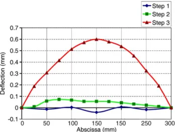
A second set of experiments has been conducted on a sandwich beam extracted from the structure. The aim was to find out which components of the sandwich are responsible for the residual stresses. The removal operations are illustrated in Fig. 5. The beam is 50 mm wide. The displacement field is then measured by means of a testing
device, which simply supports the beam (Fig. 6) on both ends. The first step consists of cutting the beam from the panel. The residual stress field then becomes unidirectional. Through the second step, the effect of the edges on the shape of the beam is analyzed. This stems from a study conducted in[11]in which some sharp corners in the sandwich have been found to cause very high stress concentrations at the beam’s tips. Here, the removal of the edges has no significant effect in terms of deflection of the beam. The last step is the removal of the outer skin in order to release residual stresses included in this component. Deflection variations (Fig. 7) are taken in a regular 300 mm-long part of the beam (Fig. 6). The graph inFig. 7shows that the most important effect is due to the skin removal: the beam tends to flatten out. This leads to the conclusion that internal stresses probably remain in tension and in compression in the skins and in shear in the foam core. A possible interpretation of the curvature is to calculate the correspond-ing bendcorrespond-ing moment that must be applied in order to return to the initial shape (before cutting). The result is presented inTable 2. In addition, it may be noted that the sandwich structure is not symmetrical through the thickness. The beam deflection due to heating will be compared to the
Fig. 4. FEMo of the panel and transverse displacement field. Table 1
Properties of the sandwich panel
Component Thickness (mm) Stacking sequence Outer skin 1.6 1 Twill fabric K308
2 Stitched fabrics 08 1 Twill fabric C308 Inner skin 0.7 1 Twill fabric K308
1 Twill fabric 08 1 Twill fabric C308 Core 50
response of FEMo in the ‘finite element modelling’ section below.
2.3. Material properties
Thermal expansion and mechanical tests have been conducted on the constitutive parts of the sandwich in order to quantify the properties required for the FEMo analysis. The identification has been made on the two different plies used in the lamination of the sandwich shell. These are a
twill woven carbon fabric and a stitched [G45] made of two unidirectional plies. The properties of the core have been taken from the manufacturer’s datasheet. The estimated material properties required for modelling are listed in
Table 3. The 08 direction of the panel and of the laminates is the x axis plotted inFig. 5.
2.3.1. Skins
In order to characterize the constitutive plies of the skins, two specific plates (called twill and stitched) have been manufactured with the same process as that used for the sandwich shell. The twill plate is made of a twill balanced fabric and has a [0,G30]Sstacking sequence. This ensures a
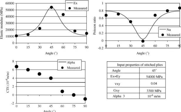
mirror symmetry and produces a quasi-isotropic composite laminate. In the stitched plate, six layers have been stacked in the 08 direction. A mirror symmetry cannot be exactly used here, and the direction of maximum stiffness is 458. From each plate, seven coupons have been cut every 158 from 0 to 908 (Fig. 8).
From the stress–strain curves obtained, the elastic modulus, the Poisson’s ratios and the coefficients of thermal expansion could be measured. Results confirm that the twill laminate can be considered as a quasi-isotropic material. For the stitched laminate, these properties are plotted in Fig. 9 and show that the behaviour cannot be considered as quasi-isotropic. More-over, classical laminate theory cannot match completely these results because, due to its constitution, the laminate should have the same properties in the directions (q), (Kq), and (p/2Kq). A compromise has been found in the choice of the properties of this layer: the evolution of elastic and thermal parameters versus angle is plotted in addition to experimental results. The discrepancy is probably due to movement of the stitched layers during lamination: dry layers are very deformable and the specific angle of 458 can vary rapidly by 5–108 under a stretching action. Nevertheless, elastic properties are well simulated. Only the evolution of the coefficient of thermal expansion is not satisfactory because the variations around the average vary from negative to positive values.
Fig. 6. Test device for curvature evolution on sandwich beams.
Fig. 7. Deflection of the beam after part removal.
Table 2
Stiffness of the sandwich beam
Thickness Bending stiffness (N) Curvature Moment (N m/m) Sandwich 52.3 mm 4.09!107 5.3!10K5 2170
A correction of this problem would lead to a new design of the skins lamination.
2.3.2. Core
The foam core is a very soft material compared to the skins. Its properties are recalled in Table 3 from the
manufacturer’s datasheet. A special feature of the core properties is the difference in stiffness from tension to compression. This particularity could not be taken into account in modelling, but it may have a significant effect on the stress and strain fields in the sandwich shell and beam. The core is considered here as a linear elastic and
Fig. 8. Geometry and direction of the tensile coupons. Table 3
Material properties
Constitutive materials properties of the sandwich Geometric Mechanical CTE!106m/m Twill fabric Carbon T300, [0;90] 220 g/m2, Thickness 0.23 mm ExZEyZ40 GPa, nxyZ0.1, GxyZ3 GPa 3
Stitched ply Carbon T300, 2 layers at [G45] 440 g/m2, Thickness 0.45 mm ExZEyZ56 GPa, nxyZ0.04, GxyZ3.3 GPa 3 Resin Aralditee LY5052—HY5052 Fiber volume fraction:
40!Vf!46
Core Klegecelle R55 55 kg/m3 E
compressionZ77 MPa, EtensionZ51 MPa, GZ27 MPa, nZ0.32
35
isotropic material, and its behaviour has to be included as three-dimensional in modelling with tensile Young’s modulus. Indeed, because of the sandwich curvature, the thermal expansion of the core through the thickness leads to a variation of this curvature.
3. Modelling of the sandwich beam
Modelling is now focused on the behaviour of the beam extracted from the shell in order to simulate a
heating experiment applied on the beam. In this test, the beam is simply supported at the ends and heated with a temperature-controlled airflow. The upper and lower displacements in the mid-section are recorded. Deflec-tion and thickness variaDeflec-tion of the beam can be deduced after an increase of 60 8C, representing the heating of the structure from room to curing temperature.
3.1. Thermo-mechanical analysis
After heating, the core has forced the curved composite shell to expand through the thickness and the skins have also expanded; this leads to a new internal equilibrium and the existence of internal stresses. This effect can be taken into account in the finite element calculations if the core is modelled with three-dimensional elements. The skins are considered in a plane stress state with the same stacking sequence as for the panel (Table 1). The finite element code Cast3M capability for coupled thermo-mechanical heat transfer analysis is used in order to model heat conduction in the multi-layer composite sandwich structure and to determine the elastic strain and stress induced by temperature variations.
Fig. 10. FEMo of the sandwich beam.
Fig. 11. Deflection of the beam and thickness variation vs CTE of the stitched layer.
Table 4
FEMo results of stress-state in the plies of the beam after 60 8C heating
Thickness (mm) Stiffness matrix Stresses (MPa) (in the coordinate system of each ply) Ply sxx syy sxy Inner skin 0.7 3:28 1:16 0 1:16 3:28 0 0 0 1:06 0 B @ 1 C A!104 Twill [K30] 7.3 4.4 0.1 Twill [0] 6.1 0.7 K0.1 Twill [30] 4.6 K2.9 0.1 Outer skin 1.6 3:06 2:16 0 2:16 3:06 0 0 0 2:20 0 B @ 1 C A!104 Twill [K30] 26.2 28.1 K1.2 Stitched [45] K5.5 K6.5 0.1 Stitched [45] K6.4 K8.6 0.1 Twill [K30] 23.1 19.6 1.0
Both steady-state and transient heat transfer finite element capabilities have been used for computations, but here only the first one is taken into consideration. Predictions are made with both composite shell and second order tetrahedral and full Lagrange heat conduction brick elements (Fig. 10). Classical thermal boundary conditions such as the surface heat flux or the properties of the surface convection must be specified. In order to model the experimental facilities, only surface convection boundary conditions are used.
3.2. Results
At first, deflection results have been calculated versus the CTE value of the stitched layers, varying from K1!10K6 to 7!10K68CK1 as mentioned in Fig. 9. Resulting deflection and thickness variation of the beam are plotted in Fig. 11 and compared to experimental values. The calculated deflection is sensitive to this parameter, and the value of CTE for the stitched layers which fits the experiment is close to 4.7!10K68CK1. This choice of a constant CTE must be done because its evolution shown in Fig. 9 cannot be reproduced in numerical simulations. Thickness variation from the test and the simulation are very close, which indicates that the CTE of the core is satisfactory. Results in terms of stresses in the skins are calculated from the model with the above-mentioned CTE value and given in Table 4. A significant stress level (maximum of 28.1 MPa in a twill layer of the outer skin) is created by the internal equilibrium and shows that the highest stresses are located in the outer skin and due to the difference of CTE between the four constitutive layers.
Compared to the stress level measured on the panel from strain analysis (maximum of 7 MPa in one of the stitched plies), it seems that this increase of 60 8C generates more stresses than the ones remaining in the structure after manufacturing. These stress levels are not completely comparable, but this order of magnitude is a typical one that may create creep deformations and affect the geometrical stability of the structure.
4. Conclusion
The approach presented in this article is based on a procedure of characterization of residual stresses that can be applied to any sandwich structure for which destructive tests are possible. Data collected among displacements, curva-tures or strains have been selected and consistently
compared with calculations. These specific results have given some orders of magnitude of residual stresses, but have also underlined the need for accurate mechanical and thermal material properties. Indeed, some parameters like the evolution of the CTE of the stitched layers are not explained by classical laminate theory, and require more accurate investigations. This approach is not comprehensive yet, because only a few data and measurements are available for the core. Moreover, there is no up-to-date measurement technique for stress analysis and thermal characterization and only the thickness variation of the beam with temperature could be validated. Work on the thermo-mechanical and viscous properties of the core are probably the next aspects to study.
References
[1] Bogetti TA, Gillespie JW. Process-induced stress and deformation in thick-section thermoset composite laminates. J Compos Mater 1992; 26(5):626–59.
[2] White SR, Hahn HT. Process modeling of composite materials: residual stress development during cure. Part II. Experimental validation. J Compos Mater 1992;26(16):2423–53.
[3] Ridgard C. Accuracy and distortion of composite parts and tools: causes and solutions. SME Tech Paper, Tooling Compos’93 1993, 93–113.
[4] Radford DW, Fu S, Derringer D. In: Massard T, Vautrin A, editors. Measurement of manufacturing distortion in flat composite laminates. CD-ROM proceedings of the 12th international conference on composite materials (ICCM 12), p. Paper 574.
[5] Johnston A, Vaziri R, Poursartip A. A plane strain model for process induced deformation of laminated composite structures. J Compos Mater 2001;35(16):1435–69.
[6] Fernlund G, Rahman N, Courdji R, Bresslauer M, Poursartip A, Willden K, et al. Experimental and numerical study of the effect of cure cycle, tool surface, aspect ratio, and the lay-up on the dimensional stability of autoclave-processed composite parts. Compos Part A 2002;33:341–51.
[7] Gigliotti M, Wisnom MR, Potter KD. Development of curvature during the cure of AS4/8552 [0/90] unsymmetric composite plates. Compos Sci Technol 2003;63:187–97.
[8] Matsunaga H. Assessment of a global higher-order deformation theory for laminated composite and sandwich plates. Compos Struct 2002;56(3):279–91.
[9] Matsunaga H. Interlaminar stress analysis of laminated composite and sandwich circular arches subjected to thermal/mechanical loading. Compos Struct 2003;60(3):345–58.
[10] Matsunaga H. A comparison between 2-D single-layer and 3-D layerwise theories for computing interlaminar stresses of laminated composite and sandwich plates subjected to thermal loadings. Compos Struct 2004;64:161–77.
[11] Yung-Neng Cheng, Shyong Lee. Reduction of the concentrated residual stress on the edges of a sandwich plate. J Mater Process Technol 2002;123:371–6.