HAL Id: hal-03187656
https://hal.archives-ouvertes.fr/hal-03187656
Submitted on 1 Apr 2021
HAL is a multi-disciplinary open access
archive for the deposit and dissemination of
sci-entific research documents, whether they are
pub-lished or not. The documents may come from
teaching and research institutions in France or
abroad, or from public or private research centers.
L’archive ouverte pluridisciplinaire HAL, est
destinée au dépôt et à la diffusion de documents
scientifiques de niveau recherche, publiés ou non,
émanant des établissements d’enseignement et de
recherche français ou étrangers, des laboratoires
publics ou privés.
Arthur Le Camus, Yannick Petit, Jean-Philippe Bérubé, Matthieu Bellec,
Lionel Canioni, Réal Vallée
To cite this version:
Arthur Le Camus, Yannick Petit, Jean-Philippe Bérubé, Matthieu Bellec, Lionel Canioni, et al..
Direct-laser-written integrated mid-IR directional couplers in a BGG glass. Optics Express,
Opti-cal Society of America - OSA Publishing, 2021, 29 (6), pp.8531-8541. �10.1364/OE.409527�.
�hal-03187656�
Direct-laser-written integrated mid-IR directional
couplers in a BGG glass
A
RTHURL
EC
AMUS,
1,2Y
ANNICKP
ETIT,
2,3J
EAN-P
HILIPPEB
ÉRUBÉ,
1M
ATTHIEUB
ELLEC,
1,2,4L
IONELC
ANIONI,
2 ANDR
ÉALV
ALLÉE1,*1Centre d’Optique, Photonique et Laser (COPL), 2375 rue de la Terrasse, Université Laval, Québec
G1V 0A6, Canada
2Université de Bordeaux, CNRS, CEA, CELIA, UMR 5107, F- 33405 Talence, France 3Université de Bordeaux, CNRS, ICMCB, UMR 5026, F- 33608 Pessac, France 4Universit e Côte d’Azur, CNRS, INPHYNI, France
*rvallee@copl.ulaval.ca
Abstract: The development of coherent sources and other optical components for the
mid-infrared has been hampered by the lack of sturdy materials that can withstand high power radiation or exposition to harsh environment. BGG glasses are robust materials transmitting over the 2.5–5 µm region. We report here the direct femtosecond laser fabrication of efficient directional couplers integrated in a BGG glass chip. The photonic components are characterized from 2.1 to 4.2 µm and compared to similar structures inscribed in silica glass samples. At 2.85 µm, a 99% relative cross transmission is reported in BGG glass. The experimental measurements are in good agreement with the coupled mode theory for wavelengths up to 3.5 µm.
© 2021 Optical Society of America under the terms of theOSA Open Access Publishing Agreement
1. Introduction
The mid-infrared (mid-IR) region of the electromagnetic spectrum is of particular interest for a wide range of applications, among which the detection of fundamental molecular vibrations in the environment [1,2], or for biomedical uses including laser surgery [3,4] dermatology or dentistry.
Direct laser writing (DLW) is a powerful tool for the fabrication of integrated devices based on waveguides which truly opens the possibility to extend the density of integration of components in three dimensions. Fabrication of buried waveguides [5] and more complex devices like directional couplers [6,7] were reported in silica based glasses.
Pure fused silica is a material of choice, mechanically strong, chemically stable and with a glass transition temperature higher than 1000◦C. This material is also well known in the field of DLW, where it has been thoroughly studied for more than 20 years. However, the transmission of pure fused silica is limited in the IR to roughly 3.5 µm, for high quality OH-free samples. Single-mode mid-IR waveguides have recently been fabricated in such silica samples [8]. They operate near 3.5 µm which appears as the upper wavelength limit for applications with silica glasses. In the mid-IR, most commonly used glasses are chalcogenide and fluoride glasses. Directional couplers designed for stellar interferometry have been successfully produced in GaLaS [9], ZBLAN [10], and GeAsSe glass systems [11], but these type material are not especially robust compared to silica.
Heavy metal oxide glasses of the system BaO-Ga2O3-GeO2(BGG) have an extended
trans-mission in the mid-IR when compared to fused silica. It allows one to target applications in the 3-5 µm window, while maintaining superior mechanical, chemical and thermal characteristics [12]. Crucible made BGG glasses tend to contain a significant amount of OH-ions impurities, causing high absorption in mid-IR around 3 µm. A way to get rid of the hydrogen is to add an halogen compound during the material synthesis, such as fluoride [13]. Previous DLW studies
#409527 https://doi.org/10.1364/OE.409527
showed the great potential of the BGG glasses [14]: smooth and high positive refractive index change (∆n) and fabrication of waveguides with remarkable transmission in the mid-IR for laser inscribed waveguides. Samples with smaller OH absorption were successfully made, replacing the barium oxide by the barium fluoride. The properties of the so-called oxyfluoride BGG glass formed this way (simply named BGG glass hereafter) are noticeably different [15]. Under laser exposure, it shows similar waveguiding structures but with lower refractive index modifications (∼60% smaller).
We demonstrate here the first prototype components for mid-IR in a BGG glass, namely integrated evanescent field directional couplers, and we compare it with fused silica components of the same kind. A multiple-pass approach with a partial overlapping between the successive laser tracks was chosen to get a better control on the waveguide shape to improve the mode with standard mid-IR fibers. It also allows to increase the amplitude of the refractive index modification in silica samples. We tested the couplers transmission at a wavelength of 2.85 µm and with a broadband source emitting between 2.1 and 4.2 µm, so as to demonstrate the high potential of BGG glass based components for the mid-IR.
2. Mid-IR waveguides fabrication
2.1. Glass samples
The BGG glass sample (17.5 BaF2, 17.5 Ga2O3, 65 GeO2in mol%) was prepared by the classical
melting-quenching technique. The powders were mixed into a Pt-Au crucible and melted at a temperature of 1300◦C during 30 min. The melt was poured on a metal plate at room temperature and annealed at 575◦C during 5 h. The glass sample was finally cut and polished before laser inscription. The high purity fused silica sample used as reference material is a F300 grade from Heraeus.
2.2. Direct-laser-writing fabrication
As sketched in Fig.1(a), the DLW technique consists in tightly focusing an ultrashort IR laser in a bulk transparent glass sample. Via a nonlinear absorption process, the refractive index is locally modified at the micrometer scale. The typical increase is ∆n ∼ 10−3. By translating the
sample in the three dimensions, arbitrary guiding photonic structures are nowadays routinely fabricated. Both the writing laser, the focusing system and the material properties play a major role on the final performances of the devices. Here, each glass sample (BGG or silica) require different writing conditions to produce waveguiding structures operating efficiently in the mid-IR range. For BGG glass, the writing laser source used is delivering 380 fs pulses (FWHM) at 1030 nm (MXR Impulse, Clark). For silica, sub-100 fs are usually preferred to obtained the required type I positive refractive index modifications. Thus, a system with shorter pulses of 85 fs (FWHM) and emission wavelength of 800 nm is used (Coherent, RegA). Both sources operate at 250 kHz repetition rate. The laser beam is focused 150 µm below the surface, using 50× microscope objectives with numerical apertures (NA) of 0.42 (Mitutoyo LCD Plan Apo NIR) and 0.55 (Mitutoyo M Plan Apo), for the BGG and silica samples respectively. In both setups, the laser is linearly polarized along z (see Fig.1). The beam is shaped via a cylindrical lens telescope to provide, at the entrance pupil of the objective, a circular beam of 4 mm in diameter with the appropriate phase which led to the formation of wider and almost circular structures [16]. With the considered irradiation parameters, the transverse dimensions of a waveguide resulting from a single laser track were typically 8 µm × 12 µm for BGG and 10 µm × 10 µm for silica. Those values were estimated from from post-inscription observations. As shown in Fig.1(a), the sample is then translated along the z axis to produce a cm-long waveguide.
To match the mid-IR fiber laser mode and ensure a smoother refractive index modification, the cross-section of the waveguide is increased up to nearly 20 µm in diameter by overlapping
multiple tracks [see Figs.1(a) and (b)]. The pitch between each consecutive pass is 1.6 µm horizontally and 3.5 µm vertically for the BGG sample (0.6 µm and 0.6 µm respectively) for the silica sample. Note that, with a pitch in silica 2.7 times smaller than that in BGG, there is a lateral overlap of 2.5 multi-passes in BGG (resp. 8.3 in silica). This was necessary to ensure a sufficiently large index modification in silica as a single laser pass showed only 5 × 10⁻⁴in silica (resp. 2.5 × 10⁻³in BGG). The overall waveguiding structure is composed of 20 lines (resp. 80 lines). Following the laser inscription, the sample end faces are ground and polished. The written structures are first examined using a standard bright field optical microscope (Olympus IX71). Figures1(c) and (d) shows the transverse section (left panels) and longitudinal section (central panels) bright field microscope images of the waveguides written in BGG (c) and silica (d) glass samples. The pulse energy is 0.5 µJ (resp. 0.8 µJ) and the translation stages move at constant velocity 1 mm/s (resp. 5 mm/s). The waveguide cross-section is almost circular with a diameter of 21±1 µm for BGG and 14,5±1 µm for silica.
Fig. 1. (a) Sketch of the direct-laser writing technique used to fabricate the mid-IR integrated
devices. A multi-pass approach allows to write smooth and homogeneous waveguides with a larger cross-section (typically 20 µm wide). (b) Lateral pattern of the overlapped laser tracks. The gray zone corresponds to size of the modified area after a single-pass for BGG (8 µm × 12 µm) and silica (10 µm × 10 µm). The crosses indicate the position of each consecutive pass. The pitch for BGG is 1.6 µm horizontally and 3.5 µm vertically (0.6 µm and 0.6 µm respectively for silica). (c-d). Transverse (left panels) and longitudinal (central panels) bright field microscope images of waveguides written in BGG (c) and silica (d) glass samples. The right panels are the corresponding optical phase difference (OPD) images. The red crosses indicate the position where OPD is 0 nm. The white bars is 20 µm. For BGG (resp. silica), the writing laser emits at 1030 nm (resp. 800 nm) and delivers pulses of duration 380 fs (resp. 85 fs) at energy 0.5 µJ (resp. 0.8 µJ) with a repetition rate of 250 kHz. The translation stages move at constant velocity 1 mm/s (resp. 5 mm/s).
Then, the microscope camera is equipped with a modified Hartmann grating (Phasics, SID4Bio) which allows to image the optical phase difference (OPD) induced by the waveguide [17,18]. Note that the illumination wavelength is centered at 550 nm. Figures1(c) and (d) (right panels) presents the OPD images for BGG and silica glass samples, respectively. The raw OPD images have no flat background, mainly due to sample irregularities. An offset is applied on each image to set 0 nm OPD at the waveguide border (indicated by a red cross). Measuring the central thickness e of the waveguide [see Fig.1(c)] and assuming that the structure is radially homogeneous, the value of the corresponding refractive index modification is estimated as ∆n= OPD/e [19]. The OPD measurements, performed for multiple samples and at different locations along the waveguide, were reproducible within a 1 nm precision. The accuracy of the thickness measurement is limited to ±1 µm. Overall, this leads to a ∆n uncertainty of ±1×10⁻⁴. The corresponding refractive index
changes are therefore estimated to ∆n= 3.0 ± 0.1 × 10⁻³for BGG and ∆n= 2.5 ± 0.1 × 10⁻³
for silica. Considering the 600 nm lateral resolution of our imaging system, the refractive index modification appears, in both cases, rather smooth (especially as shown with the longitudinal OPD images). Moreover, if we consider circular step-index waveguides, the LP11mode cutoff
wavelength is estimated to 2.8 µm (resp. 1.6 µm) and the NA is 0.1 (resp. 0.08) for BGG (resp. silica).
Note that such refractive index changes are in good agreement with the values previously reported in the literature for mid-IR operation. For instance, in fused silica, ∆n as high as 1×10⁻² has been presented [8], while in GLS glass, values of 3×10⁻³have been reported [20]. In ZBLAN typical laser induced ∆n are negative and with magnitude lower than 1×10⁻³[10,21]. In our previous study of BGG glasses [14], we fabricated waveguides exhibiting ∆n up to 1×10⁻²in high OH-content BGG samples and about 2.5×10⁻³in low OH-content BGG.
It’s worth mentioning that, in fused silica, the fabrication of large waveguides (i.e. ∼20 µm diameter) appeared to systematically result in mm-long cracks along the z axis of the waveguides. Although not shown here, we observe formation of cracks for waveguides with a diameter typically greater than 16 µm. Those cracks were typically appearing after the polishing process and were fully developing from the ends facets to the bulk within few minutes or few hours. Cracks appearing after polishing, along the side of laser-induced 10 µ m × 10 µ m rectangular waveguides were recently reported in silica [22,23] In the irradiation regime considered here and in [22,23], the increase of the refractive index is usually associated to the local densification of the structure [24,25]. Our hypothesis on the origin of the cracks is related to the densification of silica : the stress generated around the multiple-pass waveguide, due to the density difference appears to increase with its size until a crack develops. Thus, to prevent the crack formation, we design smaller waveguide sections with a lower ∆n. Additionally, the end faces were simply finely polished so that the waveguides terminate at about 30 µm from the end faces. No cracks were observed in silica with such writing and polishing procedures. In the BGG sample, no cracks were observed, even for large (> 20 µm) waveguides. The difference between the two glasses is not fully understood yet. The different behaviour could result from either different deposited energy and induced thermal history, or their distinct thermo-mechanical properties. Note that the laser writing process in BGG is believed to be highly thermal, since the cross-section of a single pass-waveguide is significantly larger than the size of the generated plasma. Higher temperatures involved in BGG may help reducing residual stress and thus prevent the formation of cracks.
Individual straight waveguides were characterized with a fiber laser emitting at 2.85 µm [26]. Using a single-mode fluorozirconate fiber (ZFG SM 14/250, Le Verre Fluoré), the light is butt-coupled to the device input port via a 3-axis precise translation stage (MAX313D, Thorlabs).
An identical fiber set-up is used to collect the light at the output port. The output power is measured with a thermopile detector (XLP12, Gentec). The optical fibers position are optimized to ensure a maximal transmission through the Fabry-Perot (FP) cavities formed between the fibers and the device facets. The corresponding Fresnel losses, LFP, were calculated, by considering
plane wave propagation in an asymmetric FP cavity, to be 0.04 dB per facet. The transmitted powers are normalized with Prefwhich corresponds to the power measured in the absence of
device by butt-coupling the injecting and the collecting optical fibers. The overall losses (averaged over three waveguides), Ltot, are 3.01 dB and 2.4 dB for BGG and silica respectively. These
measurements include both the reflection losses, discussed above, and the losses due to the mode mismatch between the fiber and the waveguides. A commercial software (Ansis Lumerical) is used to numerically calculate i) the modes of both the fiber and the waveguides, considering circular step-index structures and ii) the corresponding mode overlap. The mode matching losses,
Lmode, are found to be 0.27 dB and 0.55 dB per facet for BGG and silica, respectively. Knowing
the sample length l, the propagation losses of an inscribed waveguide can thus be estimated as [Ltot− 2(LFP+ Lmode)]/l. With a waveguide length of 1.49 cm (resp. 2.30 cm) for BGG (resp.
silica), we obtain propagation losses of 1.6±0.1 dB/cm (resp. 0.5±0.1 dB/cm). In comparison, at 2.85 µm, the attenuation of the bulk samples are measured to 1.3 dB/cm for BGG and 0.2 dB/cm for silica. Thus, at 2.85 µm, BGG and silica waveguides both show propagation losses 0.3 dB/cm higher than the corresponding intrinsic bulk losses. Although F300 silica transmission still looks competitive at 2.85 µm and ultimately up to 3.5 µm [8], BGG shows much better transmission above 3.5 µm which makes this glass a good candidate for the 3.5-5 µm range.
3. Mid-IR integrated directional couplers
3.1. Theoretical description of a directional coupler
The optical directional coupler is composed of two evanescently coupled single-mode waveguides, denoted A and B, as sketched in Fig.2(a). The corresponding propagation constants are defined as βAand βB. In order to ease light injection and output collection, the extremities of the photonic
structure is typically composed of straight parts where the waveguides, separated by a distance
D, can be considered as not coupled. They are adiabatically brought close via S-bends and interact in a central straight region over a distance L. In the coupling region, the center-to-center separation is d.
In the weak coupling regime, meaning that the presence of one waveguide does not affect significantly the transverse mode profile of the other waveguide, a directional coupler is typically described by the coupled-mode theory (CMT) [27–30]. The evolution of the complex field amplitude of each lossless guided mode, EA,B(z), is ruled by the following set of coupled equations:
idEA
dz = βAEA+ κABEB idEB
dz = βBEB+ κBAEA
(1)
κAB and κBAare the coupling coefficients taking into account the transverse field envelope of
each waveguide. For nearly equal waveguides, that differ slightly on refractive index (typically ≲ 10−4), we have κAB ≃κBA = κ [31]. For two identical step-index circular waveguides (i.e.
βA= βB= β), κ is a function of the wavelength λ and the distance d and simplifies as [27,31]:
κ(d, λ) = λ 2πnc(λ) u2 a2V2 K0(wd/a) K12(w) (2)
where a is the waveguide radius and nc(λ) = n0(λ) + ∆n is the refractive index of the waveguide
with n0the surrounding glass refractive index. K0,1are the modified Bessel functions. We note u= k0a(n2c− n2eff)
1/2, w= k
0a(n2eff− n20)1/2and V = u2+ w2= k0a(n2c− n20)
1/2with k
0= 2π/λ
and neff = β/k0.
Considering the central straight interaction region only (i.e. κ is independent of z), for single waveguide excitation, the relative cross transmission, defined as Pi+2/(P3+ P4) where P1,2,3,4
Fig. 2. (a) Schematic of the directional coupler composed of two evanescently coupled
waveguides A and B. Both input ports (1 and 2) and output ports (3 and 4) are separated by a distance D. They are brought close via S-bend parts (with curvature radius R) and interact over a straight segment L. In the coupling region, waveguides are separated by a distance d. (b) Simplified model of the directional coupler composed of two circular step-index waveguides. The S-bend parts are modeled by a straight part with effective length Leff.
are the powers measured at the ports 1 to 4 and with i= {1, 2} the input waveguide’s label, can be expressed as T= (κ2/Ω2) sin2(ΩL) where Ω2 = κ2+ (∆β/2)2with ∆β= βA−βB= k0∆neff.
Moreover, it’s worth mentioning that besides the straight interaction region, light slightly couples from one waveguide to another in the S-bends too. To take this effect into account, a phenomenological approach, sketched in Fig.2(b), is to consider an effective interaction length
Leff. In these conditions, the power cross transmission now simply reads: T = κ
2
Ω2 sin
2(Ω[L+ L
eff]), (3)
where Leffcan be numerically inferred as discussed below.
3.2. Design and fabrication of a mid-IR directional coupler
Various couplers with interaction length L varying from 0 to 5 mm are inscribed in the BGG sample. As presented in the previous section, the diameter of each mid-IR waveguide is 21 µm and its refractive index modification is ∆n= 3 × 10⁻³. The distances d and D are fixed to 25 µm and 175 µm respectively. The S-bend parts consist in two arcs, with a constant but opposite radius of curvature. To ensure negligible curvature-induced losses (at λ= 2.85 µm), the radius of curvature is set to 75 mm.
3.3. Directional coupler transmission at 2.85 µm in BGG and silica glasses
Directional couplers are characterized with the same fiber laser source emitting at 2.85 µm. For each coupler, light is injected in one input port (P1 = 100 mW, P2 = 0 and P1 = 0, P2 = 100
mW, alternately) and the transmitted power is measured at the two output ports, P3and P4. The
normalized total transmissions (P3+ P4)/Pref, where Prefis the reference power as previously
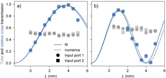
introduced, are plotted in Fig.3for BGG and silica glasses (gray symbols). The averaged total transmissions are 0.49 and 0.58 respectively, which is identical to that of a straight waveguide of the same length, indicating that no significant losses are induced by the bends, thus justifying the choice of 75 mm for the radii of curvature.
The measured relative cross transmissions P3,4/(P3+ P4) are shown in Fig.3for BGG (a) and
silica (b) glasses. First, for BGG, a maximum transmission of 99% is measured for L= 4 mm. The experimental data are fitted using the Eq. (3). As discussed later, the coupler at L= 5 mm might have been damaged and is thus excluded from the fitting procedure. The obtained coupling coefficient κ= 0.29 mm−1 is in perfect agreement with the value 0.29 mm−1 expected from
reported values in GSL chalcogenide glasses [32]. Note that the detuning could, in principle, be compensated during the writing process by e.g. adapting the writing velocity, as in [32]. The 21% cross transmission measured at L= 0 mm is due to the extra coupling occurring in the bent parts including both the coupling before and after the straight region. The corresponding effective length, extracted from the fit, is Leff = 1.70 mm. Then, the same fitting procedure
is applied to the experimental data from the silica samples. We obtained κ= 0.51 mm−1and
Leff = 1.89 mm. The calculated coupling strength is also 0.51 mm−1. However, we observe
a larger scattering in the data for silica. This can be attributed to i) the laser source stability used for silica structuring (see Sec.2.2) and ii) the highest sensitivity to laser power variation of silica compare to BGG [14]. The resulting waveguides might present different individual properties (e.g. effective refractive index), which result in strongly asymmetric couplers. This is confirmed by the relatively large detuning ∆neff= 1.47 × 10⁻⁴extracted from the fit, as well as
by the maximal energy transfer ratio being limited to 90% only, as shown in Fig.3(b).
Fig. 3. Total transmission (gray markers) and relative cross transmission (blue markers and
lines) of directional couplers with varying interaction length L for BGG (a) and fused silica (b). The measurement is performed at 2.85 µm. Full circles (resp. squares) correspond to input power in port 1 (resp. port 2). The blue line is the fit based on Eq. (3). The fit parameters are κ= 0.29 mm−1, ∆neff = 0.35 × 10⁻⁴and Leff = 1.70 mm for BGG and κ = 0.51 mm−1, ∆n
eff= 1.57 × 10⁻⁴and Leff= 1.89 mm for silica (see text for details). The blue dashed lines are numerical results obtained from Eqs. (2) and (3) for straight directional couplers with circular step-index waveguides. The radius a= 10.6 µm (resp. 7.25 µm) and the separation d= 25 µm (resp. 20 µm) correspond to the experimental configuration for BGG (resp. silica). The coupler effective length Leffand the detuning ∆neffcorrespond to the fit parameters previously discussed.
In summary, efficient directional couplers with ∼99% cross transmission at 2.85 µm are realized in a BGG sample. In contrast, the lack of stability during the writing definitively prevent any efficient directional coupler operating in the mid-IR in silica. Since BGG has shown both its superiority to silica in terms of transmission and remarkable smooth behavior under DLW procedures, the next section is thus devoted to the spectral characterization of the directional couplers specifically inscribed in BGG.
3.4. Broadband transmission of mid-IR directional couplers in BGG
Using a 4f-system composed of ZnSe lenses, a supercontinuum source (Targazh, Le Verre Fluoré) emitting from 2.1 to 4.2 µm is injected in an optical fiber (ZFG SM 14/250, Le Verre fluoré) butt-coupled to the input port of the directional coupler. The output signal is collected by a
similar fiber connected to an optical spectrum analyzer (OSA) operating from 1.9 to 5.5 µm (AQ6376, Yokogawa). For each measurement, the signal is injected in the port 1 and collected in the two output ports. The top panels in the Fig.4shows the raw transmitted powers P3(blue) and P4(orange) for two directional couplers with L= 4 mm (left) and 5 mm (right). The gray line
corresponds to the reference power measured without any device. All spectra exhibit absorption lines between 2.5 and 2.8 µm that are due to atmospheric humidity in the OSA. High frequency modulations (periods from 10 to 30 nm with amplitude < 1 dBm) caused by the Fabry-Perot effect occurring between the device output facet and the collection fiber are also observed.
The relative cross transmission P3/(P3+ P4) is plotted (linear scale) in the bottom panels
(light gray lines). The red lines correspond to the numerically filtered signal. First, for L= 4 mm
Fig. 4. Raw output powers in log scale (top rows) and relative cross transmissions in linear
scale (bottom rows) for directional couplers fabricated in a BGG glass with effective lengths L= 4 mm (left panels) and 5 mm (right panels). The port 1 of the coupler is excited with a broadband source extended from 2.1 to 4.2 µm. The gray line on top-left panel shows the reference output power (i.e. without any device). The blue (resp. orange) lines on top panels correspond to the power measured at port 3 (resp. port 4). On bottom panels, the red lines show the numerically filtered experimental data (the light gray lines behind are the raw data). The gray dashed lines are the numerical results obtained from Eqs. (2) and (3) for straight directional couplers with circular step-index waveguides of radius a= 10.6 µm, separation d= 25 µm, ∆neff= 0.35 × 10⁻⁴and Leff= 1.7 mm. For the blue dashed lines, ∆neffand
[Fig.4(bottom left)], the transmission reaches a maximum of 99% at 2.75 µm then drops to 7% at 4.09 µm. This behavior is a direct consequence of the wavelength dependence of the coupling strength [see Eq. (2)]. Indeed, at fixed separation d, as the wavelength increases, the waveguide modes spread, their overlap grows which thus results in increasing the coupling. Note that for λ>3.5 µm, the calculated coupling coefficient saturates and even decreases which is unphysical. This suggests that up to this limit the weak coupling regime is not valid anymore. The gray dashed line corresponds to the numerical simulations of Eqs. (2) and (3) with Leff= 1.7 mm and
∆neff = 0.35 × 10⁻⁴(parameters extracted from the fit of experimental measurements performed
at 2.85 µm, see Sec.3.3). As expected, the agreement is very good at 2.85 µm but deviates for lower and larger wavelengths. To get a closest match, Leffand ∆neffare slightly adjusted to 2.0
mm and 0.20 ×10⁻⁴respectively (dashed blue line). In that case, the agreement is almost perfect
up to 3.5 µm.
Then, for L= 5 mm, a very similar behavior is observed except that the maximal transmitted signal, measured at 2.6 µm, is limited to 82%. Adjusting Leffand ∆neffto 2.0 mm and 0.77 ×10⁻⁴
respectively allows to get a much better agreement. In this case, as anticipated in the Fig.3(a), when the transmission measured at 2.85 µm has been excluded from the fit procedure, the large ∆neffsuggests that this coupler is indeed damaged.
Complementary, numerical 2D-FDTD simulations (Ansis Lumerical) were also performed to check the validity of our directional coupler model. We designed simplified planar coupled waveguides structure with similar characteristics (refractive index, propagation constant, sepa-ration and interaction lengths ranging from 1 to 5 mm). The excitation wavelengths were 2.8 µm and 4.2 µm. At 2.8 µm, we observed a good agreement, with a maximum relative cross transmission of 99.4% at L= 4 mm. On the other hand, at 4.2 µm, the relative cross transmission reaches a maximum of 93.7% for L= 1.8 mm, then drops to a minimum of 5.8% at 4.7 mm. Although the waveguides are perfectly identical, the complete power transfer is not achieved at a large wavelength. FDTD simulations also show that Leffdepends on the wavelength, as it
increases for larger wavelengths especially above 3.5 µm where the weak coupling regime is no more relevant.
Although coupled-mode theory seems well suited to model the directional coupler behavior up to 3.5 µm, it clearly fails for larger wavelength. FDTD simulations thus suggests that the normal-mode theory rather than the CMT [33,34] should be considered to properly model our device at large wavelengths.
4. Conclusion
We have demonstrated the first fabrication and characterization of integrated directional couplers operating in the mid-IR in the highly promising heavy metal oxyfluoride BGG glass. For comparison, similar photonic components have been also realized in silica glass samples.
First, using a multi-pass direct femtosecond laser writing technique, we fabricated individual waveguides with a controlled cross-section. This allowed to ensure smooth and homogeneous photonic structures and to guaranty single-mode propagation in the mid-IR range. The maximal refractive index changes have been estimated to 3.0 ± 0.1 × 10⁻³for BGG and 2.5 ± 0.1 × 10⁻³ for silica. The propagation losses have been measured to 1.6±0.1 dB/cm and 0.5±0.1 dB/cm respectively. Then, directional couplers, consisting in two evanescently coupled single-mode waveguides, have been fabricated. At 2.85 µm, a 99% cross transmission has been reported in BGG. In contrast, the lack of glass response stability during the writing definitively prevent any efficient directional coupler operating in the mid-IR in silica. We show that such experimental behaviors are in very good agreement with the coupled-mode theory. Finally, directional couplers in BGG have been characterized using a supercontinuum source emitting from 2.1 to 4.2 µm. We showed that the CMT is not well suited to model the photonic structure for wavelength larger
than 3.5 µm. Additional FDTD simulations performed with simplified coupler configurations, showed that the complete power transfer is indeed not achieved at large wavelengths.
Interestingly, although not detailed here, it is worth noting that waveguides fabricated in BGG demonstrated good resilience (when annealed up to 300◦C) as well as good flux resistance (when exposed to a 10 W continuous laser emitting at 2.85 µm). No damages of the glass or the waveguides have been observed under these conditions.
Overall, these results highlight the high potential of the heavy metal oxyfluoride BGG glass for the fabrication of robust and integrated mid-IR photonics components.
Funding.National Research Council Canada (IRCPJ469414); Horizon 2020 Framework Programme (823941). Disclosures.The authors declare that there are no conflicts of interest related to this article.
References
1. Ł. Kornaszewski, N. Gayraud, J. M. Stone, W. N. MacPherson, A. K. George, J. C. Knight, D. P. Hand, and D. T. Reid, “Mid-infrared methane detection in a photonic bandgap fiber using a broadband optical parametric oscillator,”
Opt. Express15(18), 11219–11224 (2007).
2. F. Charpentier, B. Bureau, J. Troles, C. Boussard-Plédel, K. Michel-Le Pierrès, F. Smektala, and J.-L. Adam, “Infrared monitoring of underground CO2storage using chalcogenide glass fibers,”Opt. Mater.31(3), 496–500 (2009).
3. V. A. Serebryakov, E. V. Bo˘ıko, N. N. Petrishchev, and A. V. Yan, “Medical applications of mid-IR lasers. problems and prospects,”J. Opt. Technol.77(1), 6–17 (2010).
4. S. Amini-Nik, D. Kraemer, M. L. Cowan, K. Gunaratne, P. Nadesan, B. A. Alman, and R. J. D. Miller, “Ultrafast mid-IR laser scalpel: Protein signals of the fundamental limits to minimally invasive surgery,”PLoS One5(9),
e13053 (2010).
5. K. M. Davis, K. Miura, N. Sugimoto, and K. Hirao, “Writing waveguides in glass with a femtosecond laser,”Opt. Lett.21(21), 1729–1731 (1996).
6. A. M. Streltsov and N. F. Borrelli, “Fabrication and analysis of a directional coupler written in glass by nanojoule femtosecond laser pulses,”Opt. Lett.26(1), 42–43 (2001).
7. K. Minoshima, A. M. Kowalevicz, E. P. Ippen, and J. G. Fujimoto, “Fabrication of coupled mode photonic devices in glass by nonlinear femtosecond laser materials processing,”Opt. Express10(15), 645–652 (2002).
8. J. Martínez, A. Ródenas, T. Fernandez, J. R. V. de Aldana, R. R. Thomson, M. Aguiló, A. K. Kar, J. Solis, and F. Díaz, “3D laser-written silica glass step-index high-contrast waveguides for the 3.5 µm mid-infrared range,”Opt. Lett.40(24), 5818–5821 (2015).
9. A. Arriola, S. Mukherjee, D. Choudhury, L. Labadie, and R. R. Thomson, “Ultrafast laser inscription of mid-IR directional couplers for stellar interferometry,”Opt. Lett.39(16), 4820–4822 (2014).
10. J. Tepper, L. Labadie, S. Gross, A. Arriola, S. Minardi, R. Diener, and M. J. Withford, “Ultrafast laser inscription in ZBLAN integrated optics chips for mid-IR beam combination in astronomical interferometry,”Opt. Express25(17),
20642–20653 (2017).
11. H. L. Butcher, D. G. MacLachlan, D. Lee, R. R. Thomson, and D. Weidmann, “Ultrafast laser-inscribed mid-infrared evanescent field directional couplers in geasse chalcogenide glass,”OSA Continuum1(1), 221–228 (2018).
12. S. S. Bayya, G. D. Chin, J. S. Sanghera, and I. D. Aggarwal, “Germanate glass as a window for high energy laser systems,”Opt. Express14(24), 11687–11693 (2006).
13. S. S. Bayya, J. S. Sanghera, and I. D. Aggarwal, “Optical transmission of BGG glass material,” U.S. patent 7,285,509 B2 (Oct. 23, 2007).
14. J.-P. Bérubé, A. L. Camus, S. H. Messaddeq, Y. Petit, Y. Messaddeq, L. Canioni, and R. Vallée, “Femtosecond laser direct inscription of mid-IR transmitting waveguides in BGG glasses,”Opt. Mater. Express7(9), 3124–3135 (2017).
15. S. Zhang, M. Xu, X. Chen, Y. Zhang, L. Calvez, X. Zhang, Y. Xu, Y. Huai, and Y. Jin, “Enhanced thermostability, thermo-optics, and thermomechanical properties of barium gallo-germanium oxyfluoride glasses and glass-ceramics,”
J. Am. Ceram. Soc.96(8), 2461–2466 (2013).
16. G. Cerullo, R. Osellame, S. Taccheo, M. Marangoni, D. Polli, R. Ramponi, P. Laporta, and S. D. Silvestri, “Femtosecond micromachining of symmetric waveguides at 1.5 µm by astigmatic beam focusing,”Opt. Lett.27(21),
1938–1940 (2002).
17. J.-C. Chanteloup, “Multiple-wave lateral shearing interferometry for wave-front sensing,”Appl. Opt.44(9), 1559–1571
(2005).
18. S. Velghe, J. Primot, N. Guérineau, M. Cohen, and B. Wattellier, “Wave-front reconstruction from multidirectional phase derivatives generated by multilateral shearing interferometers,”Opt. Lett.30(3), 245–247 (2005).
19. E. Bélanger, J.-P. Bérubé, B. de Dorlodot, P. Marquet, and R. Vallée, “Comparative study of quantitative phase imaging techniques for refractometry of optical waveguides,”Opt. Express26(13), 17498–17510 (2018).
20. M. Hughes, W. Yang, and D. Hewak, “Fabrication and characterization of femtosecond laser written waveguides in chalcogenide glass,”Appl. Phys. Lett.90(13), 131113 (2007).
21. S. Gross, N. Jovanovic, A. Sharp, M. Ireland, J. Lawrence, and M. J. Withford, “Low loss mid-infrared ZBLAN waveguides for future astronomical applications,”Opt. Express23(6), 7946–7956 (2015).
22. T. Lee, Q. Sun, R. Ismaeel, M. Beresna, and G. Brambilla, “Low bend loss femtosecond written waveguides exploiting microcrack enhanced modal confinement,” 2019 Conf. on Lasers Electro-Optics Eur. Eur. Quantum Electron. Conf., (2019)
23. Q. Sun, T. Lee, M. Beresna, and G. Brambilla, “Control of laser induced cumulative stress for efficient processing of fused silica,”Sci. Rep.10(1), 3819 (2020).
24. J. W. Chan, T. Huser, S. Risbud, and D. M. Krol, “Structural changes in fused silica after exposure to focused femtosecond laser pulses,”Opt. Lett.26(21), 1726–1728 (2001).
25. Y. Bellouard, A. Champion, B. McMillen, S. Mukherjee, R. R. Thomson, C. Pépin, P. Gillet, and Y. Cheng, “Stress-state manipulation in fused silica via femtosecond laser irradiation,”Optica3(12), 1285–1293 (2016).
26. D. Faucher, M. Bernier, G. Androz, N. Caron, and R. Vallée, “20 W passively cooled single-mode all-fiber laser at 2.8 µm,”Opt. Lett.36(7), 1104–1106 (2011).
27. A. W. Snyder, “Coupled-mode theory for optical fibers,”J. Opt. Soc. Am.62(11), 1267–1277 (1972).
28. A. Yariv, “Coupled-mode theory for guided-wave optics,”IEEE J. Quantum Electron.9(9), 919–933 (1973).
29. A. Snyder and J. Love, Optical Waveguide Theory (Springer, 1983).
30. D. Marcuse, Theory of Dielectric Optical Waveguides, 2nd Edition (Academic Press, 1991).
31. A. W. Snyder and A. Ankiewicz, “Optical fiber couplers-optimum solution for unequal cores,”J. Lightwave Technol. 6(3), 463–474 (1988).
32. R. Diener, S. Nolte, T. Pertsch, and S. Minardi, “Effects of stress on neighboring laser written waveguides in gallium lanthanum sulfide,”Appl. Phys. Lett.112(11), 111908 (2018).
33. Y. Suematsu and K. Kishino, “Coupling coefficient in strongly coupled dielectric waveguides,”Radio Sci.12(4),
587–592 (1977).
34. Z.-M. Mao, X.-S. Fang, and B.-H. Li, “Mode excitation theory and experiment of single-mode fiber directional coupler with strong coupling,”J. Lightwave Technol.4(4), 466–472 (1986).