HAL Id: hal-02994640
https://hal.archives-ouvertes.fr/hal-02994640
Submitted on 8 Nov 2020
HAL is a multi-disciplinary open access
archive for the deposit and dissemination of
sci-entific research documents, whether they are
pub-lished or not. The documents may come from
teaching and research institutions in France or
abroad, or from public or private research centers.
L’archive ouverte pluridisciplinaire HAL, est
destinée au dépôt et à la diffusion de documents
scientifiques de niveau recherche, publiés ou non,
émanant des établissements d’enseignement et de
recherche français ou étrangers, des laboratoires
publics ou privés.
Safety in a Human Robot Interactive: Application to
Haptic Perception
Vamsi Krishna Guda, Damien Chablat, Christine Chevallereau
To cite this version:
Vamsi Krishna Guda, Damien Chablat, Christine Chevallereau. Safety in a Human Robot Interactive:
Application to Haptic Perception. Virtual, Augmented and Mixed Reality. Design and Interaction,
pp.562-574, 2020, �10.1007/978-3-030-49695-1_38�. �hal-02994640�
Safety in a Human Robot Interactive:
Application to Haptic Perception
V.K Guda1, D. Chablat1, C. Chevallereau1
Laboratoire des Sciences du Num´erique de Nantes (LS2N) UMR CNRS 6004, Nantes, 44300, France
[email protected], [email protected], [email protected]
1
Abstract
Usually, traditional haptic interfaces, such as Virtuose 6DOF [1], are used in the design phases by engineers [2]. Such interfaces are safe. However, the user can apply a force/torque but cannot really feel textures and appreciate material quality. These interfaces have a limited workspace, low stiffness and are very expensive. New haptic interfaces using an industrial robots or a cobot (robots specially designed to work in Human-Robot environments) can be used as a haptic interface with intermittent contacts [3, 4]. For application considered in this paper, the cobot carries several specimens of texture on its end-effector, to allow contact between a finger of the user and the robot.
Safety is an important aspect in Human Robot Interactions (HRI) [5], even with the use of cobots, because contacts are expected. The purpose of this paper is to introduce a new methodology to define the basic placement of the robot in relation to the human body and for the planning and control of movements during HRIs to ensure safety.
2
Introduction
Safety is important in interactions between human and robots (HRI). Robots can perform powerful and fast movements that can be dangerous to the humans around them. Involuntary contact between these robots and humans is a threat. This is particularly important in a virtual reality context where humans equipped with a headset will not be able to anticipate the robot’s movements. Today more than ever, men work closely with robots. In the case of intermittent contact interface ICI, contact is inevitable between humans and robots. Cobots are best suited to such a scenario, but in terms of human safety, accident prevention can always be improved [6]. These robots are designed to work at limited speeds during potential contacts. Moreover, it must be ensured that the desired contacts with the robot during interaction will not result into an necessary restart of the robot after a safety stop [7].
The model of haptic perception is the human sense of touch. The deep sen-sibility is an integral part of this human sense. It includes the senses of force,
position and movement of the different parts of the human body. In our case the objective is development of a new generation of haptic devices called intermit-tent contact interfaces (ICI) [8]. ICI are based on the principle of controlling a robot to follow the user’s movements remotely, and only come into contact when a haptic interaction must be created, for example to simulate a contact between his hand and the virtual environment. The combination of visual virtual real-ity and haptic device can provide users with the sensation of touching virtual objects of varying shapes, using pseudo-haptic effects [9, 10].
3
Context of the study
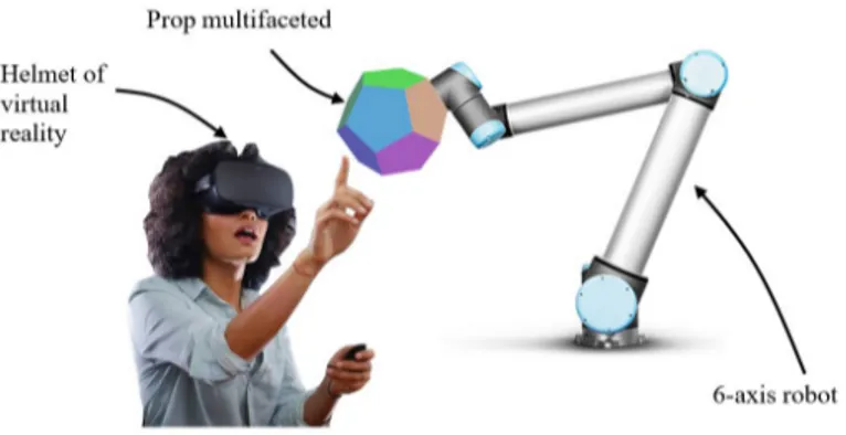
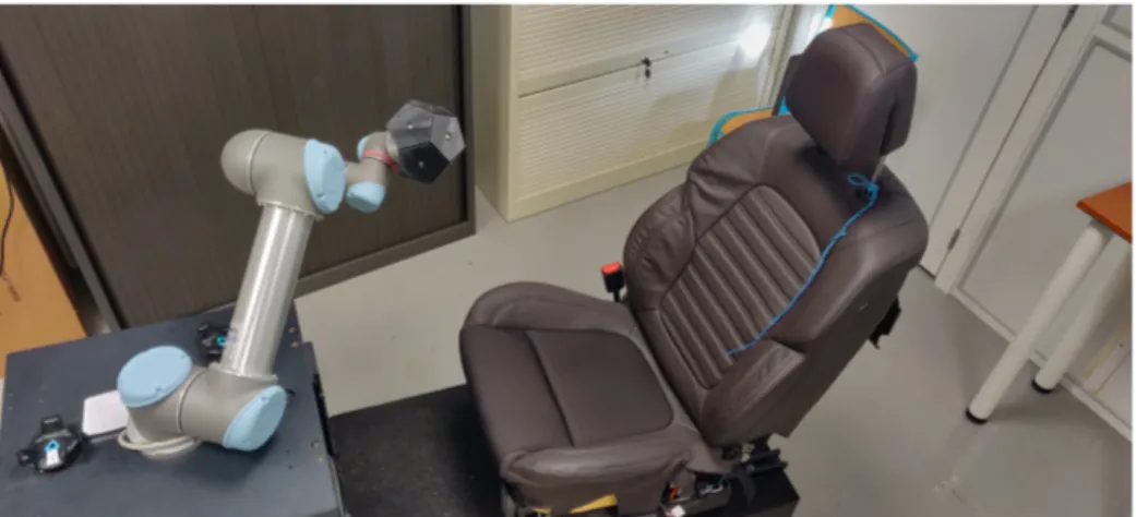
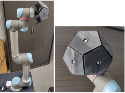
The context of the study is the evaluation of the perceived quality of a virtual car interior during the first design phases. In a given scenario, the user sits in the real world for a visual virtual reality experience inside the car. The user wears a helmet and cannot see the robot, which explains the safety problem (Figure 1). While the user is trying to interact with the virtual object in the environment, the robot must come and position a sample of the material associated with the local surface, in order to provide a tactical sense of touching the object [11, 12]. A motion capture system based on HTC vive trackers is used to know the position of the body and especially the hand used for interaction as well as the position of the chair and the robot [13] (Figure 2). Currently, the prop can carry six different materials (Figure 3). The robot is fixed on a 75 cm high table and the user sits on a seat 60 cm above the floor.
Fig. 1. Conceptual scheme of the experimental platform
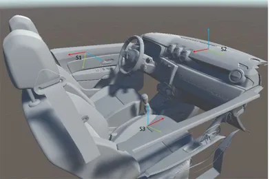
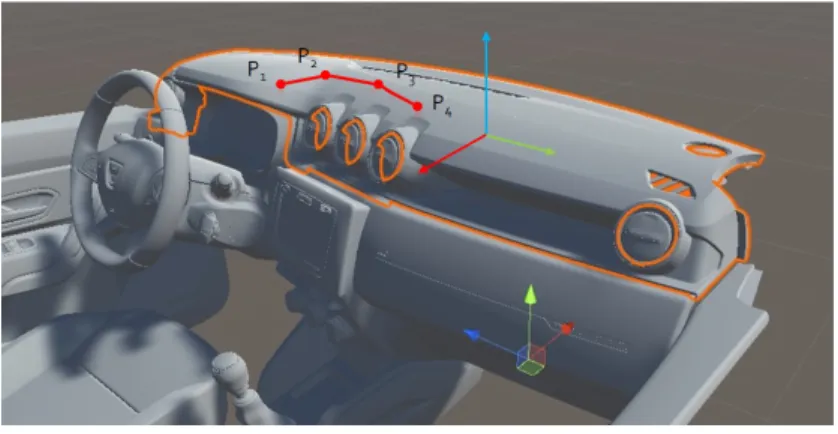
So in this scenario, ideally we want the robot workspace to cover all the virtual environment (in this case the passenger compartment of the car) the user could interact. Figure 4 depicts the interior of a Dacia Duster and three areas to touch.
Fig. 2. The complete system setup for human robot interaction
In this process the robot should avoid unwanted collisions with the user. In this context we have two types of contacts: (i) task contacts and (ii) unwanted contacts.
Task contacts are contacts that are related with the actual task of the robot and therefore they are expected and mainly initiated by the robot. They are located on the frontiers of the virtual environment and occurs between the end-effector and the human’s hand.
Unwanted contacts are collisions that happen when the robot end-effector or robot body comes in contact with the user while it is not expected in the task description.
To manage these collisions, we come up on a strategy for safety of user in ICI scenario. We consider multiple control factors like planning, workspace /working posture and placement.
Planning: There are two aspects of planning of robot motion in this scenario: (i) reaching the desired next ICI location safely, (ii) being able to track the user hand at the frontier of the virtual environment without having collision with the user, to prepare a future motion of the ICI to its desired location as soon as possible. Having a better planning control helps in avoiding collisions.
Workspace / Working posture: Constraining the robot’s working posture for the entire workspace reduces the risk of collisions. In practice this avoid recon-figuration of the robot to change of working posture (such as elbow up or elbow down configuration) and such large amplitude motion can lead to collision.
Placement : The placement of the robot with respect to the user and the environment has to be defined in order that the robot is able to carry the prop to the limit of the virtual environment that the user wants to explore while avoiding collision with the human. It is better if all the part of the robot is keep outside of the interior of the virtual car. This requirement is especialy difficult to reach for the region defined by S3(see Figure 4).
Fig. 3. (a) The UR5 robot with a prop attached to the end-effector and (b) The prop used to carry six sample textures. The lateral surface of the prop are denoted 1 to 5 and can be changed by a rotation of the last axis of the robot. The frontal surface of the prop is denoted 6. A displacement of the robot is required to present a lateral surface and then the frontal surface at the same cartesian location
Find a convenient location for the robot is an not easy task and it is the main subject of the paper.
4
Base placement of the robot for reach the desired poses
4.1 Requirement
The base placement of the robot, is defined in order to be able to place the prop at the point that the human want to explore. Since the robot arm studied has dimension which are close to the dimension of human arm, the ideal robot location would be in the location where the user is seated. However to avoid collisions, we cannot place the robot there. In fact, we would like the robot to be located outside the passenger compartment of the virtual car. It is expected that the user body (specially the chest and neck) should be outside the workspace of the robot, such that there will be no possibility of contact between body parts of the user and the robot’s arm. The robot placement should be such that it can reach all the desired contact regions in the required orientation.
4.2 Methodology
The Robot The cobot used in this paper is UR5 from Universal Robots [14]. It is a 6 DOF robot able to interact with humans in a shared space or to work
Fig. 4. Example of virtual environment and a set of regions to be reached
safely in close proximity. We constrain the posture of the robot to stay in a single aspect, i.e. a particular configuration [15]. In this case, it is elbow up. This helps us in avoiding crossing singularities, during motions. The selection of the specific posture is done by studying the various reachability ranges of different postures and selecting the posture with maximum reachability range without collision between the arm and its support.
Now, for the posture of the robot defined as elbow up, the workspace of the robot is defined as the position location of the effector with respect to the base of the robot, defining a range of orientations for the end-effector.
The workspace is calculated using the ROS package Reuleaux, via a discrete set of spheres of 5 cm diameter. For each center of the sphere and desired ori-entation of the end-effector, the inverse geometric model is used (with imposed posture) and if a solution exist, the sphere is conserved. At this point, we have all the information about each point in the workspace that can be reached with the preset posture of the robot. If several orientation of the end effector is desired, the intersection of the workspace for each orientation is defined. The workspace of the robot for two orientations and the intersections of both orientations are illustrated on Figure 6.
These orientations under test are obtained as a factor of the surfaces of the prop that will be used for this tests. The prop that we consider has 6 surfaces. Figure 5 shows the major frames of interest in this test scenario. the TCP frame is the frame at the end of robot without any attachment. We will need to consider two transforms from the TCP to the surface of the prop in contact. For the S2
Region as shown in Figure 7. We will considering that all the six surfaces of the prop can be touched. In this region we can have maximum surface interaction with robot prop to compare the feeling with several texture.
When building the workspace, the table linked to the robot is taken into account as an obstacle, but since the pose of the robot in the environment is not known, the other obstacles are not considered.
Fig. 5. The prop used in this experiment
Fig. 6. The workspace of the robot are build for orientation 1 (denoted W1), orientation
2 (denoted W2) and for both orientation by intersection of W1 and W2 to obtain W3.
The Task For interaction between the virtual environment and robot tool, lets consider three major regions in the passenger compartment of the car. These regions are defined as S1, S2 and S3 located at the extremes of the car for the
driver: the door, the dash board and the seat next to the user/driver. In the three regions S1, S2 and S3, we define four points P1, ..., P4 that we want the
robot to reach.
For S1 region as shown in Figure 8, which is the door close to the user, we
want for the robot being able to reach this surface with the prop surface 6. This correspond to the orientation 1. The points must belong to the workspace W1
For the S2region, shown in Figure 7, we can have a maximum surface
inter-action with robot prop, we imposed that the surface 6 or surface 1 to 5 of the prop can be presented in order to test several material. A rotation of the last axis of the robot allows to change the surface of the prop from surface 1 to 5. To achieve this, the points has to be reachable by the two orientations. The points must belong to the workspace W3shown in Figure 6.
Finally, the S3 region is defined in the middle of the seat close to driver, as
shown in Figure 9. For this task, the points must belong to workspace W2shown
in Figure 6.
Fig. 7. S2 - region
The Robot Placement Now to find the best base placement of the robot, we discretize the possible position of the robot. The set of possible location are expressed as a set of sphere of 8 cm of diameter that represent the paving of the space.
If the robot is fixed on the floor, the paving can include only sphere at the level of the floor. In more general case, as the one studied here, a 3D paving can be considered. The vertical coordinate of the best pose of the robot will defined the good height for the table supporting the robot.
The task is defined as previously by the set of points that we want to reach with a given orientation. The workspace generated for each orientation of region is also used (This is called as reachability map [16]). A point can be reach if it belongs to the worskpace associated to the desired orientation (for example W1).
The algorithm developed is based on the Reuleaux package [17] available via ROS [18] and using libraries [19, 20].
The methodology can include any number of point tasks. For each point associated with one orientation i.e. one workspace Wi, all the sphere inside of
the workspace is covered and placed at the point studied, and the corresponding pose of the robot is registered. The location of the based is associated to the sphere paving the possible placement of the robot. The number of point reachable from this base location is increased.
After considering all the point of interest (12 point in our study), the possible placement of the robot to achieve the task is defined as the sphere where the number of reachable is maximum.
From this set of base locations, we remove the base locations that coincide with the location of the user. Depending on the number of desired points that can be reached, the points are categorized. This gives the possible robot base location more suited for this scenario.
Algorithm 1: Base Placement of the Robot Result: Set of robot base locations input (Reachability Map, Task Points); procedure 1 create basemap;
for each task point Pi do;
INVtransform from Pi and obtain b the base location of the robot;
cluster b and assign the spheres Sk;
increment the index associated to sphere Sk;
save Sk;
end for;
end procedure;
procedure 2 base placement; access spheres Sk;
find spheres with max base index; exclude the spheres from inside the car; end procedure;
4.3 Results
Test were performed to find the robot base placement for given set of point the robot has to reach with a defined orientation. In the tested scenario, the dimension of the table under consideration is 75 cm high and 53 cm long and wide. The base of the robot is located in the middle of the table to ensure its stability. A total of 12 task points have been defined: four task points in S3
region (Chair), four task points in S1region (Door), and four task points in S2
region (Dash board) with two sets of different orientation.
The possible robot base location are illustrated by blue sphere in Figure 10. The base location are outside the passenger compartment of car. Multiple robot base locations were found that could reach all the desired positions.
Fig. 10. Base placement for S1, S2and S3 Fig. 11. Side view for S1, S2 and S3
Fig. 12. Front view for S1, S2 and S3 Fig. 13. Top view for S1, S2 and S3
5
Obstacles avoidance
In the previous study, the obstacle of the environment (the chair and the human) was not taken into account since the location of the robot was not known. Thus
the next step is to check for the selected pose location (in Figure 10) that the points can be reached when the real environment are taken into account.
In this environment, we introduce a model of the chair and the human in rest position. For the user’s body, the dimensions considered, for user cover 75 percentile of men and women of age group 25-55 in France. The volume dimensions of the cuboid are 185 cm in height and 60 cm in width and 30 cm in thickness (Figure 14).
First the location of the robot corresponding to the actual height of the table is considered. For each pose location, the following task is considered: go from home position to each points successively.
From several candidate poses of the robot, the task cannot be achieved. For others, the task can be achieved. Two main problems were encountered:
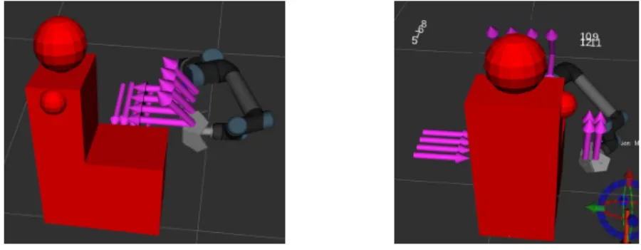
An illustration of the result is shown for the case illustrated in Figure 14. The configuration of the robot to reach a point on the passenger chair is shown in Figure 15, the robot is close to the legs of the human. The configuration of the robot to reach a point on the dashboard is shown in figure 16, the robot configuration is convenient, it is far from the human.
Fig. 14. Base location in blue and tasks points with the desired orientation in pink, 75 cm table height
To improve, the robot base placement, we can change the height of the table used. Several tests are done to determine the effect of changing the height of the table, on the position of robot base and its effect on the inclusion of the robot in the passenger compartment of the car. For performing the tests, the task points shown in Figure 17 are considered.
When the robot tries to reach the chair task points, we can see from Figure 15 that the robot goes to the passenger compartment of the car. Conversely, the same problem does not occur in Figure 19, as the height to the table is reduced by 15 cm. Similar result is shown in Figure 18 with reduced base table dimensions. It can be concluded that it is better to use a table of 60 cm height that 75 cm height for the given scenario.
Fig. 17. Base location in blue and tasks points with the desired orientation in pink, 60 cm height
Fig. 18. Interaction at dash, 60 cm height Fig. 19. Interaction at chair, 60 cm height
6
Conclusions
In this article, a collaborative robot is used as a haptic interface with intermit-tent contact. This interface is used when designing car passenger compartment to choose the textures of the materials used. The work presented allows to choose
a robot placement so that the end-effector reaches the areas of interest in the environment while ensuring the absence of collision between the robot and the user. An algorithm has been proposed define convenient placement of the robot base in order to reach several areas of interest. First results are obtained using a given height of the table that support the robot base. The results show an acces-sibility of the task but also show a robot insertion in the passenger compartment. Changing this height setting prevents this intrusion and therefore improves user safety.
Acknowledgement
This work was funded under the LobbyBot project, ANR-17-CE33 [21]. The authors of the article thank the members of the project for their help in carrying out this work, Lionel Dominjon, Sandrine Wullens, Allexandre Bouchet, Javier Posselt, Maud Marchal, Anatol Lecuyer and Victor Rodrigo Mercado Garcia.
References
1. J. Perret and P. Vercruysse, “Advantages of mechanical backdrivability for medical applications of force control,” in Conference on Computer/Robot Assisted Surgery (CRAS), 2014, pp. 84–86.
2. W. A. McNeely, “Robotic graphics: a new approach to force feedback for virtual reality,” in Proceedings of IEEE Virtual Reality Annual International Symposium. IEEE, 1993, pp. 336–341.
3. B. Araujo, R. Jota, V. Perumal, J. X. Yao, K. Singh, and D. Wigdor, “Snake charmer: Physically enabling virtual objects,” in Proceedings of the TEI’16: Tenth International Conference on Tangible, Embedded, and Embodied Interaction. ACM, 2016, pp. 218–226.
4. Y. Kim and Y. Kim, “Versatile encountered-type haptic display for vr environ-ment using a 7-dof manipulator,” in Proc. IEEE/RSJ International Conference on Intelligent Robots and Systems (IROS’2016), 2016.
5. M. A. Goodrich, A. C. Schultz et al., “Human–robot interaction: a survey,” Foun-dations and Trends® in Human–Computer Interaction, vol. 1, no. 3, pp. 203–275, 2008.
6. A. Cherubini, R. Passama, A. Crosnier, A. Lasnier, and P. Fraisse, “Collaborative manufacturing with physical human–robot interaction,” Robotics and Computer-Integrated Manufacturing, vol. 40, pp. 1–13, 2016.
7. P. Long, C. Chevallereau, D. Chablat, and A. Girin, “An industrial security system for human-robot coexistence,” Industrial Robot: An International Journal, vol. 45, no. 2, pp. 220–226, 2018.
8. O. La De Cruz, F. Gosselin, W. Bachta, and G. Morel, “Contributions to the design of a 6 dof contactless sensor intended for intermittent contact haptic in-terfaces,” in 2018 3rd International Conference on Advanced Robotics and Mecha-tronics (ICARM). IEEE, 2018, pp. 130–135.
9. Y. Ban, T. Kajinami, T. Narumi, T. Tanikawa, and M. Hirose, “Modifying an identified curved surface shape using pseudo-haptic effect,” in 2012 IEEE Haptics Symposium (HAPTICS). IEEE, 2012, pp. 211–216.
10. A. L´ecuyer, “Simulating haptic feedback using vision: A survey of research and applications of pseudo-haptic feedback,” Presence: Teleoperators and Virtual En-vironments, vol. 18, no. 1, pp. 39–53, 2009.
11. V. R. Mercado, M. Marchal, and A. L´ecuyer, “Entropia: Towards infinite surface haptic displays in virtual reality using encountered-type rotating props,” IEEE Transactions on Visualization and Computer Graphics, 2019.
12. S. V. Salazar, C. Pacchierotti, X. de Tinguy, A. Maciel, and M. Marchal, “Altering the stiffness, friction, and shape perception of tangible objects in virtual reality using wearable haptics,” IEEE Transactions on Haptics (ToH), 2020.
13. M. Tomi´c, C. Chevallereau, K. Jovanovi´c, V. Potkonjak, and A. Rodi´c, “Human to humanoid motion conversion for dual-arm manipulation tasks,” Robotica, vol. 36, no. 8, pp. 1167–1187, 2018.
14. E. H. Ostergaard, “Lightweight robot for everybody [industrial activities],” IEEE robotics & automation magazine, vol. 19, no. 4, pp. 17–18, 2012.
15. P. Wenger, “Cuspidal and noncuspidal robot manipulators,” Robotica, vol. 25, no. 6, pp. 677–689, 2007.
16. F. Zacharias, C. Borst, and G. Hirzinger, “Capturing robot workspace structure: representing robot capabilities,” in 2007 IEEE/RSJ International Conference on Intelligent Robots and Systems. Ieee, 2007, pp. 3229–3236.
17. A. Makhal and A. K. Goins, “Reuleaux: Robot Base Placement by Reachability Analysis,” ArXiv e-prints, Oct. 2017.
18. M. Quigley, K. Conley, B. Gerkey, J. Faust, T. Foote, J. Leibs, R. Wheeler, and A. Y. Ng, “Ros: an open-source robot operating system,” in ICRA workshop on open source software, vol. 3, no. 3.2. Kobe, Japan, 2009, p. 5.
19. (2019, Jun.) Kdl kinematics and dynamics library (kdl). [Online]. Available: http://wiki.ros.org/kdl
20. (2019, Jun.) Fcl flexible collision library. [Online]. Available: https://github.com/flexible-collision-library/fcl