OATAO is an open access repository that collects the work of Toulouse
researchers and makes it freely available over the web where possible
Any correspondence concerning this service should be sent
to the repository administrator:
[email protected]
This is an author’s version published in: http://oatao.univ-toulouse.fr/20876
To cite this version:
Degenève, Arthur and Jourdaine, Paul and Mirat, Clément
and Caudal, Jean and Vicqueline, Ronan and Schuller,
Thierry
Analysis of wall temperature and heat flux
distributions in a swirled combustor powered by a methane-air
and a CO2-diluted oxyflame. (2019) Fuel, 236. 1540-1547.
ISSN 0016-2361
Official URL:
https://doi.org/10.1016/j.fuel.2018.09.012
the surrounding walls, the radiative flux is expressed as[26,27]: L T T
( ( ) )
rad
g4 g i4 (4)
where Ti is the temperature of the internal surface of the quartz
window, L( )and Tgare the equivalent emissivity and the temperature
of the burned gases and g the gas absorptivity. The absorptivity g is
correlated to L( )as g/ ( )L =( / )T Tg i1.5[26]and this correlation is
in-jected in Eq.(4)yielding:
L T T T
( ) ( )
rad
g1.5 g2.5 i2.5 (5)
Modest[28]gives a rough approximation of the mean beam length =
L 3.6 /V Athat gives satisfying results, where V and A are the volume and the surrounding surface area of the considered region.
Along the combustor walls, the swirling flow is turbulent. The Ditus correlation[29]is used to estimate the convective heat flux:
= = = h T T( ) Nu 0.023Pr Re cv cv g i L h Lk 1/3 D4/5 cv a (6)
where ka is the thermal conductivity of the burned gases at
= +
Tb (Tg Ti)/2,Lthe height of the combustion chamber,NuL, Pr are
the Nusselt and Prandtl numbers and ReD is the Reynolds numbers
based on the hydraulic diameter D of the square cross section area of the combustion chamber and is also evaluated atTb.
3.3. Analysis of heat transfer regimes
In order to discriminate the origin of the thermal loads on the sidewalls, the combustion chamber volume is separated into four dis-tinct zones, as sketched inFig. 9:
1. — Zone 1 corresponds to the reaction region, where the temperature is close to the adiabatic flame temperatureTadand the axial velo-cities are high at the injector outlet. This zone corresponds to the volume delimited by the spontaneous OH∗emission shown inFig. 1a and b and lies far from the walls.
2. Zone 2 corresponds to the Inner Recirculation Zone (IRZ) of the swirling flow and is revealed by the axial velocity field plotted in
Fig. 10. Recirculation of the burned gases inside the IRZ allows flame stabilization in the center of the combustor, but this region is not in direct contact with the combustor sidewalls.
3. Zone 3 corresponds to the Outer Recirculation Zone (ORZ) high-lighted in the bottom corners inFig. 10, which is located between the flame front, the combustor sidewalls and the combustor flange. This region is essentially filled with burned gases and characterized by large-scale vortical structures and low velocities. The
temperature in this region is measured with a thermocouple, re-presented inFig. 9atz3=4r0(TC3 inFig. 2). The small flow
velo-cities in this region indicate that the convective heat transfer coef-ficient hcvat the quartz windows remains small in this zone. Wall
radiative energy transfers are presumed to be more important in this region. The ORZ stops at the height zc 8r0.
4. The last region designated as zone 4 inFig. 9 corresponds to the burned gases near the combustion chamber exhaust. The tempera-ture is also relatively homogeneous in this region and was measured with a thermocouple atz4=11r0(TC4 inFig. 2). The flow pattern
induced by the swirling motion forces the burned gases to circum-vent the large IRZ and to be redirected toward the walls with rela-tively large velocities (seeFig. 10). This flow circulation promotes wall convective heat transfer.
In this analysis, it is hypothesized that the two important zones for heat transfer to the quartz walls are zones 3 and 4. Radiative effects from zone 1 and zone 2 are discarded due to an optically thick ap-proximation of radiative energy transfer. In zone 3, only radiative heat transfer is then considered due to the low velocities of the flow in this region. In zone 4, both the radiative and convective heat fluxes are taken into account.Table 2synthesizes the different temperatures, ra-diative and thermal properties that are used to make the calculations with the model presented in Section 3.2. The thermal load on the combustor sidewalls is now analyzed with Eqs.(5) and (6)and results are compared for flame A and flame B. Simplifications are made based on the similarities of the flame (Fig. 1)and flow (Fig. 10) patterns.
The gas temperatures Tgmeasured with a thermocouple atz3=4r0
and z4=11r0 are chosen to fix the temperature throughout zone 3
(ORZ) and zone 4 (Burned gases). The mean beam length method from Modest[28]is used to determine the radiative properties of the major species within the burned gases. Data from Riviere and Soufiani[30]
are used to calculate the total emissivity L( )of the burned gases while accounting for both CO2and H2O molar fractions. The value found for the CO2-diluted flame B is twice the emissivity of the N2-diluted flame A: B( )L 2 ( )A L.
In the ORZ corresponding to zone 3, the temperature difference =
T T Tg ibetween the burned gases temperature Tg, measured with a
thermocouple, and the internal surface temperatureTi of the quartz
Fig. 9. Separation of the combustion chamber volume in different zones to model the heat transfer to the sidewalls.
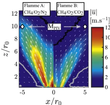
Fig. 10. 2D velocity fields in an axial plane in reacting conditions.
=0.95,P=13kW,S0=0. 75andTad=2200K. The IRZ and ORZ are
mechanisms of intense burning of oxy-flames. Combust Flame 2016;174:111–9. [7] Taamallah S, Chakroun N, Watanabe H, Shanbhogue S, Ghoniem A. On the
char-acteristic flow and flame times for scaling oxy and air flame stabilization modes in premixed swirl combustion. Proc Combust Inst 2017;36:3799–807.
[8] Jourdaine P, Mirat C, Caudal J, Lo A, Schuller T. A comparison between the sta-bilization of premixed swirling co2-diluted methane oxy-flames and methane/air flames. Fuel 2017;201:156–64.
[9] Schmitt P, Poinsot T, Schuermans B, Geigle KP. Large-eddy simulation and ex-perimental study of heat transfer, nitric oxide emissions and combustion instability in a swirled turbulent high-pressure burner. J Fluid Mech 2007;570:17–46. [10] Guiberti TF, Durox D, Scouflaire P, Schuller T. Impact of heat loss and hydrogen
enrichment on the shape of confined swirling flames. Proc Combust Inst 2015;35(2):1385–92.
[11] Tay-Wo-Chong L, Zellhuber M, Komarek T, Im HG, Polifke W. Combined influence of strain and heat loss on turbulent premixed flame stabilization. Flow Turbul Combust 2016;97(1):263–94.
[12] Gupta A, Modest MF, Haworth DC. Large-eddy simulation of turbulence-radiation interactions in a turbulent planar channel flow. J Heat Transfer
2009;131(6):061704.
[13] Zhang Y, Vicquelin R, Gicquel O, Taine J. Physical study of radiation effects on the boundary layer structure in a turbulent channel flow. Int J Heat Mass Transf 2013;61:654–66.
[14] Silvestri S, Patel A, Roekaerts D, Pecnik R. Turbulence radiation interaction in channel flow with various optical depths. J Fluid Mech 2018;834:359–84. [15] Koren C, Vicquelin R, Gicquel O. Multiphysics simulation combining large-eddy
simulation, wall heat conduction and radiative energy transfer to predict wall temperature induced by a confined premixed swirling flame. Flow Turbul Combust 2018:1–26.
[16] Jourdaine P, Mirat C, Caudal J, Schuller T. Stabilization mechanisms of swirling premixed flames with an axial-plus-tangential swirler. J Eng Gas Turb Power 2018;140:08152.
[17] Brohez S, Delvosalle C, Marlair G. A two-thermocouples probe for radiation cor-rections of measured temperatures in compartment fires. Fire Saf J
2004;39(5):399–411.
[18] Lemaire R, Menanteau S. Assessment of radiation correction methods for bare bead thermocouples in a combustion environment. Int J Therm Sci 2017;122:186–200. [19] Brübach J, Pflitsch C, Dreizler A, Atakan B. On surface temperature measurements
with thermographic phosphors: a review. Prog Energy Combust Sci 2013;39(1):37–60.
[20] Euler M, Zhou R, H.S., Dreizler A. Temperature measurements of the bluff body surface of a swirl burner using phosphor thermometry. Combust Flame 2014;161:2842–8.
[21] Guiberti T. Analysis of the topology of premixed swirl-stabilized confined flames [Ph.D. thesis]. Ecole Centrale Paris; 2015.
[22] Glarborg P, Bentzen LLB. Chemical effects of a high CO2 concentration in oxy-fuel combustion of methane. Energy Fuels 2008;22:291–6.https://doi.org/10.1021/ ef7005854. arXiv: 10.1021/ef7005854.
[23] Heraeus, Quartz glass for optics data and properties quartz glass for optics data and properties (2013) 8.http://heraeus-quarzglas.com/media/webmedialocal/ downloads/broschrenmo/DataandPropertiesOpticsfusedsilica.pdf.
[24] Combis P, Cormont P, Gallais L, Hebert D, Robin L, Rullier J-L. Evaluation of the fused silica thermal conductivity by comparing infrared thermometry measure-ments with two-dimensional simulations. Appl Phys Lett 2012;101(21):211908. [25] Rothman L, Gordon I, Barber R, Dothe H, Gamache R, Goldman A, et al. Hitemp, the
high-temperature molecular spectroscopic database. J Quant Spectrosc Radiat Transfer 2010;111(15):2139–50.
[26] Lefebvre AH, Herbert M. Heat-transfer processes in gas-turbine combustion cham-bers. Proc Inst Mech Eng 1960;174(1):463–78.
[27] Lefebvre AH, Ballal DR. Gas turbine combustion: alternative fuels and emissions. CRC Press; 2010.
[28] Modest MF. Radiative heat transfer. Academic press; 2013.
[29] Dittus F, Boelter L. Heat transfer in automobile radiators of the tubular type. Int Commun Heat Mass Transfer 1985;12(1):3–22.
[30] Rivière P, Soufiani A. Updated band model parameters for H2O, CO2, CH4and CO