HAL Id: hal-02288016
https://hal.telecom-paris.fr/hal-02288016
Submitted on 16 Apr 2021
HAL is a multi-disciplinary open access
archive for the deposit and dissemination of
sci-entific research documents, whether they are
pub-lished or not. The documents may come from
teaching and research institutions in France or
L’archive ouverte pluridisciplinaire HAL, est
destinée au dépôt et à la diffusion de documents
scientifiques de niveau recherche, publiés ou non,
émanant des établissements d’enseignement et de
recherche français ou étrangers, des laboratoires
Directing the Photography: Combining Cinematic
Rules, Indirect Light Controls and Lighting-by-Example
Quentin Galvane, Christophe Lino, Marc Christie, Rémi Cozot
To cite this version:
Quentin Galvane, Christophe Lino, Marc Christie, Rémi Cozot. Directing the Photography:
Combin-ing Cinematic Rules, Indirect Light Controls and LightCombin-ing-by-Example. Computer Graphics Forum,
Wiley, 2018, 37 (7), pp.45-53. �10.1111/cgf.13546�. �hal-02288016�
H. Fu, A. Ghosh, and J. Kopf (Guest Editors)
Directing the Photography: Combining Cinematic Rules,
Indirect Light Controls and Lighting-by-Example
Q. Galvane1, C. Lino2, M. Christie1, R. Cozot1
1Inria / University of Rennes, France,2LTCI, Telecom ParisTech, Paris-Saclay University, France
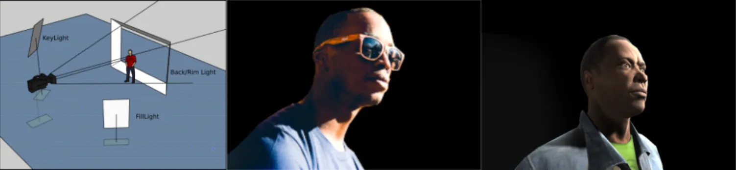
Figure 1: The 3-point-lighting technique (on the left) is a classical cinematic rule to place lights around a subject. Playing with the lights position, size, and flux considerably impacts the aesthetics and atmosphere of a scene (in the middle). We propose a technique that automati-cally computes the parameters of a 3-point-lighting setup made of area lights, given the reference image in the middle, to generate the image on the right in a virtual environment.
Abstract
The placement of lights in a 3D scene is a technical and artistic task that requires time and trained skills. Most 3D modelling tools only provide a direct control of light sources, through the manipulation of parameters such as size, location, flux (the perceived power of light) or opening angle (the light frustum). Approaches have been relying on automated or semi-automated techniques to relieve users from such low-level manipulations at the expense of an important computational cost. In this paper, guided by discussions with experts in scene and object lighting, we propose an indirect control of area light sources. We first formalize the classical 3-point lighting design principle (key-light, fill-lights and back/rim-lights) in a parametric model. Given a key-light placed in the scene, we then provide a computational approach to (i) automatically compute the position and size of fill-lights and back/rim-lights by analyzing the geometry of 3D character, and (ii) automatically compute the flux and size of key, fill and back/rim lights, given a sample reference image in a computationally efficient way. Results demonstrate the benefits of the approach on the quick lighting of 3D characters, and further demonstrate the feasibility of interactive control of multiple lights through image features.
CCS Concepts
•Computing methodologies → Computational photography; •Human-centered computing → User centered design; •Ap-plied computing → Media arts;
1. Introduction
Lighting entities in 3D environments is a central concern for who-ever wants to bring an aesthetic and emotional dimension to an image. In real photography and cinematography, there are many guiding principles to lighting (e.g. Rembrandt lighting, 3-point and 4-point lighting) [Wis12]. Surprisingly, most 3D modelling tools do not propose a strong support in this lighting stage other than
di-rect interaction with each of the lights low level parameters. Hence, individually placing each light and controlling its parameters is a complex endeavor that requires advanced skills and expertise.
To ease this creative stage, the research community has been proposing interactive or automated light placement techniques. They commonly rely on an inverse-lighting approach: the user specifies the features of his desired lighting, and a solver
deter-2 Q. Galvane, C. Lino, M. Christie, R. Cozot / Directing the Photography
mines an appropriate set of lighting parameters (position, orien-tation, flux, color of lights). Approaches are considered as lo-cal when the user controls local image features such as the po-sitions or sizes of shadows and highlights, or the shading color of lit areas [SDS∗93,PBMF07,Pel10]; or global when the user controls global image features, e.g. histogram of luminance or contrast [KPC93,CdAS12,FB14]. Lighting-by-example is another class of approaches that mixes local and global approaches; it relies on analyzing features from a reference image , and then compute light parameters to obtain a lighting style as close as possible to the reference image (e.g. encoded through an histogram of image lumi-nance [HCB16] or an image decomposition into wavelets [HO07]). The main issue of such inverse-lighting approaches is the com-putational cost of rendering and evaluating the image features each time a light parameter evolves. Optimization techniques require to extensively evaluate the cost function expressed as a distance in terms of these image features. This cost may be reduced through the use of simplified light sources (point, spot or directional lights) compatible with rasterization rendering, at the expense of lowering the realism of the computed images.
The challenge is hence to reduce the practical complexity of au-tomated light placement, while at the same time considering more complex light models such as area lights commonplace in real light-ing stages. To address this challenge, we first propose to reduce the general problem of light placement to a 3-point light setup arranged around a subject (see Figure1). This setup is composed of a number of key-lights – they represent the main source of light –, fill-lights – their role is to control shadows intensity of areas not lit by the key-lights–, and back/rim-lights – their role is to highlight the silhouette of a subject. Second we propose to rely on complex light sources, namely area lights, for which real-time rendering techniques have been proposed [HDHN16,LDSM17], hence reducing the cost of evaluating image features. And third, we adopt a two stage solving process that consists in first computing light positions and orien-tations, and second optimizing lights size, opening angle and flux. Our process can (i) automatically compute how many fill-lights and back/rim-lights are needed, together with their best placement, by analyzing the scene layout and the 3D geometry of the subject; and (ii) automatically compute the size, opening angle and flux of each area light source, given a set of desired image features extracted from a reference image. In addition, we provide the user with an interactive control of the key-light position; each change triggers the re-computation of the fill-lights and back/rim-lights.
Our contributions are:
• an indirect manipulation technique that enables a quick re-positioning and re-orienting of area lights using a 3-point cin-ematic lighting technique;
• a two-stage computation method which automatically deter-mines the number, position, orientation, size, opening angle and flux of fill-lights and back-lights, given one or more key-lights. It mixes a geometric analysis with a stochastic numerical opti-mization;
• an objective function driven by a lighting-by-example approach. It compares the distribution and gradient of image luminance.
2. Related work
Lighting is a key element in photography/cinematography [Ada56,
DeM59,Mal92,Las00,Sip10] and computer-generated contents [Wis12]. Choices in lighting aesthetics conveys the mood or at-mosphere in a picture or in a story. In real or virtual environments, professional visual content creators rely on complex lighting se-tups, the design of which is highly technical and tedious due to the large number of parameters to control and to coordinate for each light source (e.g. type of light, position, orientation, shape, size, aperture, flux, falloffs, color). The user must also determine how many lights are needed.
An extensive body of work has been devoted to tackling inverse-lighting problems, first introduced by Kawai et al. [KPC93]. All inverse-lighting methods share the common goal of computing a lighting setup, that can produce an image that corresponds as closely as possible to a desired lighting. Their differences can be analyzed along their specification of a desired lighting [PP03]: (i) Global methods, (ii) Painting-based methods (which we also refer to as local methods), (iii) Lighting-by-example based methods and (iv) Perception-based methods.
Global methods often tackle light source placement or flux prob-lems in architectural design applications [CSFN11,CdAS12,FB12,
FB14]. In this context, the lighting aesthetics in the rendered image is not a priority. Instead, the desired lighting is often specified as a set of statistical lighting features [KPC93] (e.g. mean radiance, maximum non-uniformity, or radiance variance). These methods proceed by minimizing an objective function built as a weighted linear combination of these statistical lighting features; the user role is then reduced to specifying all weights. Such global methods are not well-suited for the design of a precise image lighting aesthetics.
Painting-based methods allow a more precise control of lighting details. A user directly paints desired lighting effects onto 3D ob-jects. In the method proposed by Schoeneman et al. [SDS∗93], the user inputs a single target radiosity vector by painting on the initial rendered image of the scene. Their fully automated optimization method then addresses the flux problem for a predefined number of lights (their positions and orientations are considered as fixed). Pelaccini [PBMF07] proposed an iterative painting-based approach where the user can interactively paint lighting effects (i.e. add ra-diance) onto objects, with brushes. He can then choose which light (either an added light or an existing light) and which parameters to consider in the optimization. This greatly reduces the computa-tional complexity. Then according to each new painted stroke, the user can iteratively refine the desired lighting. Their system tack-les both the flux and placement problems. However, their system greatly relies on the user artistic skills; in particular such a system is not able to automatically determine when to add or remove a light, or which sub-set of the parameters to optimize. Such inter-active methods can then be time-consuming and tedious to use, as mentioned by Pellacini in [KP09]; according to him, such painting-based methods can actually appear less intuitive to use than indirect control methods. Moreover, painting-based methods are not well-suited for the lighting of animated contents.
Lighting-by-example methods address the main limitations of global and local approaches. Their central idea is that the desired lighting is provided as a reference image (a real image or a render of another 3D scene) or directly as another, already lit, 3D scene. Zupko and El-Nasr [ZEN09] ask the user to choose an image of an illuminated sphere that describe their desired image aesthetics. The target image is thus independent of the scene but limited to an image of a single sphere in front of a uniform background. Ha et al. proposed to define the desired lighting aesthetics with any image [HLCO10]. They encode the input lighting aesthetics as a wavelet decomposition of the radiance in the image. Their system then tries to optimize the lights in a new scene so as, when render-ing this scene, the rendered image has a similar wavelet decompo-sition. The success of their technique is however very dependent to the layout of objects on the screen. Léon et al. [LGCB14] instead extract statistical features (e.g. mean and variance luminance) from the input image. They then try to minimize the distance between the reference and output images according to these statistical features. Only the opening angle and flux of the light (a spotlight source) are accounted for in their optimization process. They use a clas-sic 3-point-lighting placement setup, which they explain is enough to achieve most of lighting aesthetics. In a way similar, Hudon et al. [HCB16] use a cost function computed as a cosine distance be-tween the luminance histograms of the reference and rendered im-ages. Their approach also differs in how they approach the choice of the number of lights. Their light source placement method is made of two steps: (i) they place a set of around ten lights onto a sphere surrounding the lit object, for which they optimize the flux, then (ii) they put off all lights for which the contribution is too small. Perception-based methods , such as [SL02,WVBT16] deal with inverse lighting problems to address non-aesthetic features, more related to the proper perception and understanding of the shape or fine details of an inspected 3D object. They are often targeting sci-entific visualization applications. Though we do not precisely tar-get this type of applications, a method close to ours is Wambecke et al. [WVBT16] which proposes a fast geometric heuristic inspired by 2-point-lighting techniques. They offer a simple heuristic, based on the analysis of an object’s geometry, allowing to place both a key-light and a fill-light to maximize the perception of the object’s shape.
Discussion To our knowledge, we provide the first inverse-lighting technique to place area lights using a real-time rasterization engine. Our approach nicely mixes the advantages of indirect control pro-posed by painting-based methods and lighting-by-example meth-ods, while optimizing in parallel area lights flux, size and position. First, the user can specify where to place the key-light in screen space (in a way similar to [PBMF07]). Second, and conversely to local methods, the user can provide any reference image as input to refine the desired aesthetics (in a way similar to [LGCB14]). Third, our method uses photographic guiding techniques (as in [WVBT16]) to model lights placement.
3. Overview
Our overall objective is to assist creatives in the design of a lighting setup around a 3D subject. The inputs of our system are (i) a single
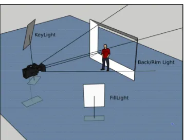
Figure 2: The design of our 3-point light setup using area lights. The Back/Rim-light is designed in a way that it is placed behind the subject as done in real-life photography/cinematography. Note that our model is designed to handle multiple key-lights, back-lights or fill-lights.
3D model (e.g. a character or an object) with no background, (ii) a camera viewing the 3D subject and (iii) a reference image that represents the desired lighting style. Our system analyzes the ref-erence image, the object’s geometry and the current placement of one or multiple key lights, to automatically compute, as an output, the placement of a collection of lights (fill-lights and back-lights).
To solve this light placement problem, we first propose a com-pact representation of the 3-point-light setup (see Section4). We then determine the number, positions and orientations of fill-lights in this setup, so that most of the object parts visible from the cam-era, but not lit by a key-light, are then lit by at least one fill-light. We analyze the object’s geometry to select all normals of a mesh triangle that are both back-facing the key-light and front-facing the camera. For this set of normals, we then use a k-means clustering on these normals. We first determine the appropriate number of fill-lights and, for each computed cluster, we create one fill-light (see Section4.2).
In a second stage, given the camera and object’s positions, and the object’s geometry, we place a specific back-light rig so that four back/rim-lights are placed (i) outside the camera’s frustum, and (ii) behind the subject (see Section4.3).
In a third stage, we use a numerical optimization process to au-tomatically improve the object’s lighting style. Given an example lighting style provided as a reference image, we optimize the size, opening angle area and flux of each light source (for both the key-lights, the fill-lights and the back-key-lights, see5.2). The cost function we minimize accounts for the distances between the histograms of luminance and the histogram of the gradient of luminance in the reference image and the render of the scene.
4 Q. Galvane, C. Lino, M. Christie, R. Cozot / Directing the Photography
Light type Manipulation steps Optimization steps Re-computed dynamically key-light d, θ, ϕ, a, s, λ, f , c f, s, λ w, h, q
fill-light λ, c f, s, λ w, h, q rim-light c f w, h, θ, ϕ, q all rim-lights d, σ, λ d, σ, λ
Table 1: Our parametric model: all lights are rectangular area lights, parameterized through their position (distance d, azimuth θ and elevation ϕ), orientation q, width w and height h, flux f and color c. We also consider design parameters such as the light aspect a (as the width/height ratio), its size s (as a scaling factor enforcing this aspect ratio). Note that for rim-lights, instead of controlling the size and aspect ratio of each light individually, we use a span parameter σ; its role is to constrain the width of side rim-lights and the height of top/ bottom rim-lights to be equal to this span value.
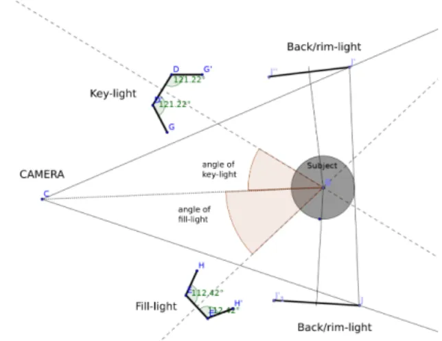
Figure 3: 2D top view of our light setup. Key and fill-lights are defined relatively to the camera-subject axis, using spherical coor-dinates, with the back/rim-lights are tangent to the camera frustum. Lights are implicitely oriented towards the subject.
4. A compact 3-point-light model
Our 3-point lighting setup is founded on several hypotheses. First, we use three types of light sources: key-lights, fill-lights and back/rim-lights. All three types are represented as rectangular area lights, of width w and height h. An area light has a flux f and a color c. Second, every light is oriented so that it always faces the subject (see Figure3), which is abstracted as a single 3D point. Hence, in our model, a light position is represented through spherical coordi-nates – it is located at distance d, azimuth θ and elevation ϕ –, while its orientation q is determined in a way similar to a camera look-at rotation. Third, we consider an opening angle λ, that controls the solid angle of its emitted flux.
To provide users with a more intuitive control over the light setup, we introduce some design parameters: the light aspect ratio a, equal to the width/height ratio; the light size s, a scaling factor from which we can determine a width and height that enforces a fixed aspect ratio. For rim-light, we introduce a light span σ. As illustrated in2, rim-lights are constrained in terms either of their height, or their width. The light span controls the value of the other unconstrained parameters; in our model, all rim lights are finally
constrained to be at the same distance of the camera and have the same span.
4.1. Interactively placing key-lights
When manipulating a key light, the user automatically triggers the recomputation of all the other light positions. To first position a key light in the environment we rely on a spherical model centered on the subject. The radius of the sphere is controlled by the user to adjust the distance of the light. Manipulating the light then consists in moving it onto this sphere. Two simple metaphors are proposed: ArcBall Light Control . We take inspiration from the Arcball metaphor for controlling cameras, and we adapt it to offer an intu-itive means to manipulate key-lights. As the user drags the mouse (i.e. left-right or up-down), the selected key-light is rotated around the subject accordingly. The controlled light naturally remains at the same distance to the subject, and is re-oriented to always face toward the sphere center.
Painting-based Light Control . We also take inspiration from previous painting-based lighting interfaces to offer a means to spec-ify directly, in image space, the areas to be lit by a key-light. Our method is designed to dynamically updated the key-lights position on manipulation. As the user highlights an object area, we analyze its geometry to select the set of visible vertices that are inside the area to lit. The direction of the key light is simply computed as the mean of all normals at these selected vertices.
4.2. Automatically placing fill-lights
Fill lights aim at softening or removing shadows produced by key lights. In other words, they should lit areas visible by the camera but which remain unlit after the key lights placement stage. The process is composed of three steps. First, given the mesh geometry of the subject and the current placement of the key lights and the camera, we compute sub-meshes representing unlit areas. Second, we compute the number of fill lights needed to lit these sub-meshes. Last, we compute the placement of fill lights by using a clustering on the vertex normals of these sub-meshes.
Computing the unlit areas . We start by extracting all vertices, as well as their associated normals, from the subject’s mesh. We then prune all vertices not visible from the camera (i.e. either back-facing or located outside the camera’s frustum). We also prune all
(a) (b)
(c) (d)
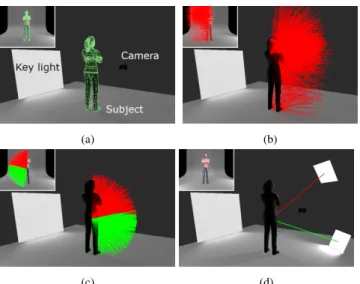
Figure 4: Creating the fill lights by (a) analyzing the geometry, (b) extracting unlit areas visible from the cameras and their normals (c) clustering the remaining normals (red and green normals are in two different clusters) and (d) placing the fill-lights
vertices that are already lit by the key light. Here, we do not check for self-occlusions of the mesh (note that this would be a costly problem by itself) but solely use the normals at remaining vertices and compare them against the direction of the key light; a vertex is considered as lit only if the dot product of its normal and the key light direction is negative.
Computing the number of fill lights Given the set of unlit ver-tices, a naive approach would be to place a fill light in the direction of the mean normal direction of all unlit vertices. However, in many cases the the subject’s geometry is too complex, which prevents a single fill light from being able to lit all sub-meshes. To solve this problem of better covering unlit areas, we perform a standard k-means clustering on this set of unlit normals. We here account for the variation of unlit normals, and compute the number of clusters (i.e. the number of fill lights, k) through the following formula
k= kmax+ 1 N N
∑
i=1 kni− ¯nkwhere niis the normal at the ithunlit vertex, ¯nis the mean normal
vector at unlit vertices and kmaxis a user-specified threshold on the
number of clusters. We experimentally found that a maximum of three fill lights is enough in most cases. Figure4shows an example of clustering obtained with our technique.
Placing the fill lights Given a set of directions, the fill lights are placed at the same distance as the key light. Their sizes and flux are computed proportionally to the size and flux of the key light.
4.3. Automatically placing back/rim-lights
The back light’s role is to highlight a subject’s contour. Tradition-ally, there are two ways to place a back light:
• either behind the subject along the camera’s axis so as to ensure it is remains hidden by the subject;
• or behind the subject, on a side, so as to be fully outside of the camera’s frustum.
Unfortunately, the magic of back-lights placed behind the target rims only really occurs on complex surfaces like hair or wool that capture the light and remain difficult to render in real time. Con-versely, the second method is less sensitive to the quality of the models and the textures. Following this main guideline, we pro-pose to model our rim light as a light rig, made ,of four area lights. These areas lights are placed behind the subject, so that one edge of each area light is touching the corresponding plane of the camera’s frustum; they are also oriented so as to light-to the subject, as illus-trated in figure3. This light rig allows a fine control on the rim ef-fect, by adjusting the distance from the subject, the width, aperture and flux of each individual rim light. While adjusting these design parameters, our system can automatically compute or re-compute the placement of the rim lights.
5. Automatic lighting style matching
Once a first 3-point-lighting setup has been computed, the user can now refine the lighting style, by manually adjusting the set of low-level light parameters such as their fluxes, sizes or open-ing angles. This however remains a tedious task, which could also rapidly break the 3-point-lighting guidelines. To remove the burden of manually tuning all parameters we here propose an optimization process which, based on our 3-point-lighting model, offers the user with an efficient means to reproduce a lighting style.
5.1. Encoding and comparing lighting styles
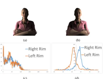
To encode the lighting style of an image, we rely on a comparison method similar to [HCB16]. They first define a desired lighting aes-thetics by using a reference image. Then then perform an optimiza-tion on lights parameters by relying on a cosine distance between the histograms of luminance in the reference and rendered images. Their method gives good results in many scenarios but fails to cap-ture some important geometric information. Figure5illustrates this limitation. While the two images have very similar histograms of luminance, their lighting aesthetics are clearly different.
To overcome this limitation, we extend their method by also us-ing the gradient in the image to enrich the representation of a light-ing aesthetics. We not only calculate an histogram of luminance but we also calculate two other histograms, respectively capturing the horizontal and vertical gradient of luminance. These additional histograms provide valuable geometric information on the object’s shading in the image; indirectly, they also provide clues on the rel-ative placement of lights. Figure5(d) demonstrates the difference in gradient histograms.
5.2. Optimizing the lighting style
The main advantage of our 3-point-light model is that it allows ma-nipulating or searching a lower-dimensional parameter space. This is valuable for interactively controlling a full 3-point-lighting setup by simply manipulating the key-light (as presented in Section4). In
6 Q. Galvane, C. Lino, M. Christie, R. Cozot / Directing the Photography
(a) (b)
(c) (d)
Figure 5: Comparison of two images rendered under two different lighting conditions (a) and (b). The two images present a similar luminance histograms (c) but different gradient histograms (d).
this new optimization step, the parameter space to search is reduced to the following subset of parameters:
• The flux, opening angle and size for the key-light;
• The flux, opening angle and size for each fill-light separately; • The distance, span and opening angle common to all rim lights; • The flux of each rim-light separately;
The dimension of our search space is then N = 3k + 10, where kis the number of placed fill-lights. By considering that kmax= 3,
the search space has at most 19 parameters.
We cast our style-matching problem into a minimization pro-cess in this sub-space. We define the objective function f (i, r) to minimize as a linear combination of the cosine distances between histograms H extracted from the reference (input) image r and the current rendered image i.
f(i, r) = w0.Ψ(HiL, HrL)+w1.Ψ(H∇vi , Hr∇v)+w2.Ψ(Hi∇h, Hr∇h)
where HL, H∇vand H∇h are respectively the histogram of
luminance, the histogram of vertical gradient and the histogram of horizontal gradient. Ψ is the cosine distance function, which takes two histograms as input, and outputs their dot product (an histogram being viewed as a real-valued vector). In the current im-plementation, weights w0, w1 and w2 have been set respectively
to the obvious values of 1, 0.5 and 0.5. This equally balances the importance of the luminance and the gradient of luminance in the optimization process.
To account for lights colors, we also extend this optimization scheme by using a separate histogram on each channel, instead of a single histograms of luminance. In the above equation, we then replace w0.Ψ(HiL, HrL) by
w0,R.Ψ(HiR, HrR) + w0,G.Ψ(HGi , HrG) + w0,B.Ψ(HiB, HrB)
where HR, HGand HBare the histogram of the red, green and blue
channels, respectively.
To solve this minimization problem, we rely on a Particle Swarm Optimization (PSO) solver. This allows efficient computations while avoiding many local minima. For comparison purposes, we also tested with other search algorithms such as the gradient de-scent or the Nelder Mead algorithms, but found that they often failed to avoid local minima. To improve the performances of our PSO solver, we strategically add a set of warm positions in addi-tion to the set of randomly sampled initial particles posiaddi-tions. We generate this set of warm positions by successively turning on only one light while other lights are turned off. The results of this opti-mization stage are presented in section9.
6. Implementation
We developed our lighting assistant within the Unity3D game en-gine. To speed up mesh and image processing, we heavily rely on general-purpose GPU programming; in the current implemen-tation, we use the Unity’s compute shaders features. To compute histograms, we only render the subject. This allows to be agnostic of the background and avoid interference. This hypothesis however implies that the input images must either be detoured or taken on a black background. All our experiments (detailed in section9) were conducted with Unity 2018 on a Core i7 @ 3.1GHz and a NVidia Quadro M2200.
7. Results
We tested our lighting design system on a variety of scenes, with different subjects and different mesh resolutions. In this section, we evaluate the performances of our interactive controller. We also evaluate the quality and accuracy of our lighting style optimizer, and validate the convergence of the particle swarm optimizer in tested scenes. Last, we evaluate the quality of our output images. All our results are presented below. We also provide a companion video showing the tool in action†.
Qualitative evaluation To evaluate the quality of both our inter-active tool and our optimizer, we tested our system on a large set of example meshes and initial lighting configurations. Figure 6
presents some of these results; additional examples are also shown in the following sections. Using different reference images from different viewpoints and different initial lighting setups as input – created by using our 3-point-lighting interactive tools – our results not only show that our 3-point-lighting model can efficiently as-sist the user in appropriately creating and placing complementary light sources, but also that our optimization process is successful in reproducing a desired lighting aesthetics.
Convergence and efficiency of the method As shown in Figure7, our system can also properly improve an existing lighting setup to match the luminance histogram of the rendered image with the histogram of the reference image. Figure7eshows the evolution of our objective function for each particle of our PSO. One can clearly observe that, by using our objective function, the optimiza-tion algorithm quickly converges toward a good soluoptimiza-tion after a few iterations only.
(a) Reference image (b) After setup (c) After optimization
Figure 6: Example of images produced with our tool. The system takes as input (a) a reference image, (b) let the user interactively place the key light while optimizing the placement of fill and rim lights and (c) optimize the lighting parameters to match the style of the reference image.
Figure8presents another interesting result. Given the same ref-erence image but different initial lights placements – with key-lights placed differently and therefore fill-key-lights and back-key-lights also placed in another configuration – our optimization process is still able to converge to a final lights placement which is very close. Expert feedback Our system was demoed and tested by both a professional director of photography and a film director. They both appreciated the use of the three-point lighting technique and the ef-fort put in the formalization of this principle. They were especially
(a) Reference image (b) Initial image (c) Rendered image
(d) Luminance histogram
(e) Optimization
Figure 7: From a reference image (a) and an initial lighting configu-ration, our system is able to reproduce the desired lighting aesthetic (c) by matching luminance histograms (d). The optimization pro-cess quickly converge after a few iterations (e).
(a) Reference image (b) After setup (c) After optimization
Figure 8: Using the same reference image (a) but starting from dif-ferent lighting conditions (b) our system is able to converge to sim-ilar solutions (c).
impressed with the results and thought of many different applica-tions for our tool. The film director would take advantage of our system mostly for previsualization purposes, to test different light-ing styles based on reference images – a common practice in the early stages of a movie production. The director of photography found the tool very promising and suggested to add additional
fea-8 Q. Galvane, C. Lino, M. Christie, R. Cozot / Directing the Photography
tures to be able to use light sources based on existing equipment (i.e. led panels, spots, reflectors, etc.), with their actual specifica-tions. While they both agreed that the lighting and shading pro-duced by the game engine was not completely realistic, they be-lieve the results are sufficient and could prove very useful in their respective fields.
Computation times As shown in Figure9, our two interactive light control tools (light painting and automatic fill-lights place-ment) run easily in real-time in most cases. When processing highly detailed meshes, the framerate may drop down during some ma-nipulations, but remains interactive (around 10 frames per second in the worst cases). When processing the 86k vertices mesh, the average framerate was around 30 frames per second.
Figure 9: Evolution of the computation time (in seconds), taken each frame, needed to place the key-light and the fill-lights. The graph displays the results for different subjects with different mesh resolutions.
When optimizing the lighting aesthetic, the computation time depends on the parameters of the PSO solver and especially the number of particles. In our case, we set the size of the swarm to 20 particles. As shown in Figure7, with this configuration it only takes a few iterations to converge. On average, it takes between 5 to 10 iterations to reach convergence, where each iteration takes around 0.4 seconds to compute – on average, 21 ms per particle per iteration.
8. Limitations
As an implementation of the 3-point lighting method, the technique presented in this paper suffers from its limitations. When placing the lights and optimizing over their parameter space, our tool only focuses on the subject. While ignoring the background is a rela-tively common practice, extending our solution to the 4-point light-ing method constitute a very interestlight-ing challenge to be addressed in future work. Regarding the optimization process, the use of the histogram of the gradient in the objective function proved to be be efficient in many cases. However, this method is sometimes not sufficient when dealing with very smooth shading. Other heuristics could be investigated to better account for the orientation of the light and its impact on the shading.
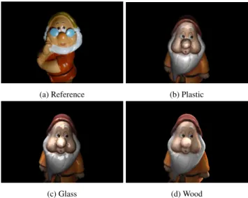
In this paper, we made the assumption that the object in the refer-ence image and the 3D model share materials of similar nature. Us-ing different materials will affect the gradient histograms of the im-ages and consequently the results. With specular objects especially, slight variations in the materials property makes the optimization process less accurate as well as the visual comparison more diffi-cult (see Figure10).
(a) Reference (b) Plastic
(c) Glass (d) Wood
Figure 10: Lighting style optimized for a reference image (a) using different types of materials for the rendered object (b), (c) and (d).
9. Conclusion
This paper has presented an inverse-lighting technique allowing to easily manipulate area lights to lit 3D subjects in virtual environ-ments, and to reproduce a given lighting style provided as a ref-erence image. We have provided a compact representation for the placement of complementary lights, that encodes a practical and well-established lighting technique in photography (the 3-point-lighting). We have proposed a hybrid optimization solution that can efficiently compare the lighting features in a reference and a render of the current scene to properly place lights and optimize their pa-rameters so as to reproduce the input lighting style. Our solution nicely couples interactive control techniques, 3D geometry and im-age processing techniques, together with recent real-time rendering of polygonal area lights. Our approach represents a first step toward the design of more complex lighting setups. In particular, we think it will open the perspective of computing lighting setups for more complex scenes, typically with fore-ground/back-ground objects, and for animated scenes.
References
[Ada56] ADAMSA.: Artificial Light Photography. Morgan and Morgan, 1956.2
[CdAS12] CASTROF.,DELACEBOE., SBERTM.: Energy-saving light positioning using heuristic search. Engineering Applications of Artificial Intelligence 25, 3 (2012), 566 – 582.2
[CSFN11] CASSOLF., SCHNEIDERP. S., FRANÃGA˘ F. H., NETOA. J. S.: Multi-objective optimization as a new approach to illumination design of interior spaces. Building and Environment 46, 2 (2011), 331 – 338.2
[DeM59] DEMILLE C. B.: The Autobiography of Cecil B. DeMille. Prentice-Hall Inc., 1959.2
[FB12] FERNÀNDEZE., BESUIEVSKYG.: Inverse lighting design for interior buildings integrating natural and artificial sources. Computers & Graphics 36, 8 (2012), 1096 – 1108. Graphics Interaction Virtual Environments and Applications 2012.2
[FB14] FERNÁNDEZE., BESUIEVSKYG.: Efficient inverse lighting: A statistical approach. Automation in Construction 37 (2014), 48 – 57.2
[HCB16] HUDON M., COZOT R., BOUATOUCHK.: Automatic light compositing using rendered images. In 2016 Digital Media Industry Academic Forum (DMIAF)(2016), pp. 176–179.2,3,5
[HDHN16] HEITZ E., DUPUYJ., HILLS., NEUBELTD.: Real-time polygonal-light shading with linearly transformed cosines. ACM Trans. Graph. 35, 4 (July 2016), 41:1–41:8.2
[HLCO10] HAH. N., LINOC., CHRISTIEM., OLIVIERP.: An interac-tive interface for lighting-by-example. In Smart Graphics, 10th Interna-tional Symposium on Smart Graphics, Banff, Canada, June 24-26, 2010, Proceedings(2010), pp. 244–252.3
[HO07] HAH. N., OLIVIER P.: Lighting-by-example with wavelets. In Proceedings of the 8th International Symposium on Smart Graphics (2007), SG ’07, pp. 110–123.2
[KP09] KERRW. B., PELLACINIF.: Toward evaluating lighting design interface paradigms for novice users. ACM Trans. Graph. 28, 3 (July 2009), 26:1–26:9.2
[KPC93] KAWAIJ. K., PAINTERJ. S., COHENM. F.: Radioptimization: Goal based rendering. In Proceedings of the 20th Annual Conference on Computer Graphics and Interactive Techniques(1993), SIGGRAPH ’93, pp. 147–154.2
[Las00] LASZLOA.: Every Frame a Rembrandt : Art and Practice of Cinematography. Focal Press, 2000.2
[LDSM17] LECOCQP., DUFAY A., SOURIMANTG., MARVIEJ.-E.: Analytic approximations for real-time area light shading. IEEE Transac-tions on Visualization and Computer Graphics 23, 5 (May 2017), 1428– 1441.2
[LGCB14] LÉONV., GRUSONA., COZOTR., BOUATOUCHK.: Auto-matic aesthetics-based lighting design with global illumination. In Pro-ceedings of Pacific Graphics 2014(2014).3
[Mal92] MALKIEWICZK.: Film Lighting. Fireside, 1992.2
[PBMF07] PELLACINI F., BATTAGLIA F., MORLEY R. K., FINKEL
-STEINA.: Lighting with paint. ACM Trans. Graph. 26, 2 (June 2007).
2,3
[Pel10] PELLACINIF.: envylight: An interface for editing natural illumi-nation. ACM Trans. Graph. 29, 4 (July 2010), 34:1–34:8.2
[PP03] PATOWG., PUEYOX.: A survey of inverse rendering problems. Computer Graphics Forum 22, 4 (2003), 663–687.2
[SDS∗93] SCHOENEMANC., DORSEYJ., SMITSB., ARVOJ., GREEN
-BERGD.: Painting with light. In Proceedings of the 20th Annual Con-ference on Computer Graphics and Interactive Techniques(1993), SIG-GRAPH ’93, pp. 143–146.2
[Sip10] SIPOST. M.: Horror Film Aesthetics : Creating the Visual Lan-guage of Fear. McFarland, 2010.2
[SL02] SHACKEDR., LISCHINSKID.: Automatic lighting design using a perceptual quality metric. Computer Graphics Forum 20, 3 (2002), 215–227.3
[Wis12] WISSLERV.: Illuminated Pixels : The Why, What, and How of Digital Lighting. Cengage Learning, 2012.1,2
[WVBT16] WAMBECKEJ., VERGNER., BONNEAUG.-P., THOLLOT
J.: Automatic lighting design from photographic rules. In Proceedings of the Eurographics Workshop on Intelligent Cinematography and Editing (2016), WICED ’16, pp. 1–8.3
[ZEN09] ZUPKOJ., EL-NASRM. S.: System for automated interactive lighting (sail). In Proceedings of the 4th International Conference on Foundations of Digital Games(2009), FDG ’09, pp. 223–230.3