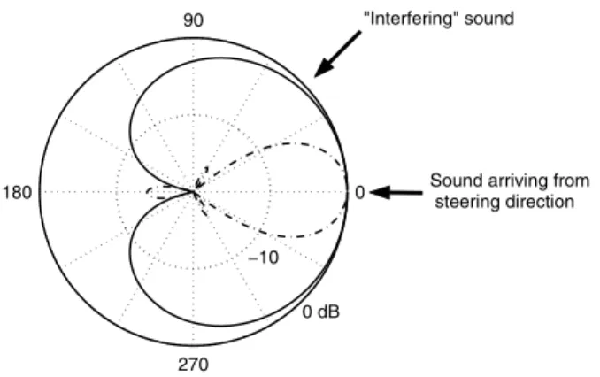
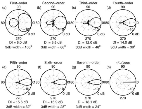
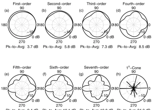
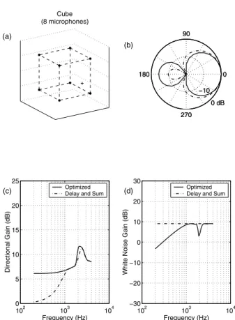
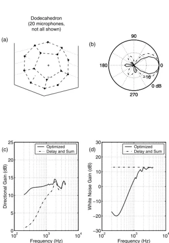
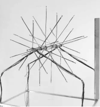
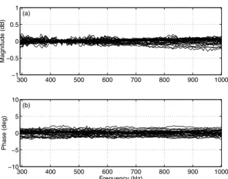
Designing a spherical microphone array for the directional analysis of reflections and reverberation
Texte intégral
Figure
Documents relatifs
It covers almost the entire test section length over a distance of 10 m. The array is moving few centimeters above the acoustic panels. A brush is used to cover the rail cavity
To validate the effectiveness of the proposed post-filter estimation method, we compare its performance to other multi-channel noise reduction techniques, including the MVDR
Parmi tous ces patrons, quels sont ceux qui permettent de construire le prisme ci-contre :.. E XERCICE
These factors are used to evaluate the compatibility of the cropping system with its economic environment (ex: compatibility of production with certification requirements),
To estimate the misidentified lepton background, we first measure the probability for a jet to produce an elec- tron or muon that satisfy the identification criteria from data using
VOCAULA, for Verification of Candidate Answers Using Linguistic Analysis, applies partial parsing of questions, candidate answers, and supporting information to the
Pazzaglia (2007), Comment on ‘‘Shale diapirism in the Quaternary tectonic evolution of the Northern Apennine, Bologna, Italy’’ by Andrea Borgia et al., J.. Dipartimento di
2 Reproduis cette figure dans
