Publisher’s version / Version de l'éditeur:
CINDE journal, 31, 3, pp. 7-13, 2010-05-01
READ THESE TERMS AND CONDITIONS CAREFULLY BEFORE USING THIS WEBSITE.
https://nrc-publications.canada.ca/eng/copyright
Vous avez des questions? Nous pouvons vous aider. Pour communiquer directement avec un auteur, consultez la
première page de la revue dans laquelle son article a été publié afin de trouver ses coordonnées. Si vous n’arrivez pas à les repérer, communiquez avec nous à PublicationsArchive-ArchivesPublications@nrc-cnrc.gc.ca.
Questions? Contact the NRC Publications Archive team at
PublicationsArchive-ArchivesPublications@nrc-cnrc.gc.ca. If you wish to email the authors directly, please see the first page of the publication for their contact information.
NRC Publications Archive
Archives des publications du CNRC
This publication could be one of several versions: author’s original, accepted manuscript or the publisher’s version. / La version de cette publication peut être l’une des suivantes : la version prépublication de l’auteur, la version acceptée du manuscrit ou la version de l’éditeur.
Access and use of this website and the material on it are subject to the Terms and Conditions set forth at
Flexible ultrasonic transducers for structural health monitoring
Wu, K.-T.; Shih, J.-L.; Kobayashi, M.; Jen, C.-K.; Bussiere, J. F.
https://publications-cnrc.canada.ca/fra/droits
L’accès à ce site Web et l’utilisation de son contenu sont assujettis aux conditions présentées dans le site LISEZ CES CONDITIONS ATTENTIVEMENT AVANT D’UTILISER CE SITE WEB.
NRC Publications Record / Notice d'Archives des publications de CNRC:
https://nrc-publications.canada.ca/eng/view/object/?id=bb7f83c9-8141-4200-a7e2-efc1b0de6117 https://publications-cnrc.canada.ca/fra/voir/objet/?id=bb7f83c9-8141-4200-a7e2-efc1b0de6117
Flexible Ultrasonic Transducers
for Structural Health Monitoring
K.-T. Wu
a,b, J.-L. Shih
a,b, M. Kobayashi
a, C.-K. Jen
aand J.F. Bussière
aa
Industrial Materials Institute, National Research Council of Canada, 75 Blvd. de Mortagne,
Boucherville, Quebec J4B 6Y4, Canada;
b
Department of Electrical and Computer Engineering, McGill University, 3480 University Street,
Montreal, Quebec H3A 2A7, Canada;
ABSTRACT
Flexible ultrasonic transducers (FUTs) which have on-site installation capability are presented for non-destructive evaluation (NDE) and structural health monitoring (SHM) purposes. These FUTs typically consist of a 70 µm thick piezoelectric lead-zirconate-titanate (PZT) composite (PZT-c) coated by a sol-gel spray technique on a 75 µm thick titanium (Ti) membrane. Such an FUT was glued onto a steel pipe of 101 mm in diameter and 4.5 mm in wall thickness and heated at up to 200°C with the glue serving as a high temperature ultrasonic couplant. The pipe thickness measurement accuracy at 200°C is estimated to be 13 µm. FUTs were also glued onto the end edge of a 2 mm thick aluminum (Al) plate to generate and receive predominantly shear-horizontal (SH) plate acoustic waves (PAWs) to detect simulated line defects at temperatures of up to 100°C. FUTs, glued onto a graphite/epoxy (Gr/Ep) composite plate, were also used for the detection of an artificial disbond. An induction type non-contact method for the evaluation of Al plates and Gr/Ep composites using FUTs is also demonstrated.
Keywords: Flexible ultrasonic transducer, structural health monitoring, high temperature ultrasonic measurement, nondestructive testing
1. INTRODUCTION
NDE of pipes in nuclear and fossil fuel power plants [1-4], chemical and petroleum plants [1, 2], has become an increasingly important element in the improvement of safety and in the extension of a structure’s life span. SHM, which may provide continuous NDE of pipes or their health conditions, has also drawn much attention recently [5-9]. Ultrasonic techniques are frequently used for these NDE and SHM purposes because of their subsurface inspection capabilities, fast inspection speeds, simplicity and ease of operation. In these applications, ultrasonic transducers (UTs) may need to be made directly in contact with structures that have surfaces with different curvatures and must also be able to operate at elevated temperatures [3, 4, 10-13]. Also Civil and military aircraft operators around the world have incurred rising maintenance costs due to their aging fleets. They are seeking ways to reduce fleet maintenance costs while still meeting airworthiness requirements. SHM is potentially a cost effective emerging technology that enables condition-based maintenance in-lieu of the traditional schedule-based NDE. For aerospace structures, composite materials such as Gr/Ep laminates are becoming the materials of choice because of their high strength to weight ratio. SHM [8, 9]and NDE technologies [1, 2] for these Gr/Ep composites are being developed to enable condition-based maintenance for cost-effective increased safety and eco-efficient designs.
In ultrasonic NDE and SHM applications, ultrasonic transducers (UTs) may need to be in direct contact with structures that have surfaces with different curvatures and/or be able to operate at elevated temperatures. However, conventional UTs having rigid flat end surfaces may in general show poor performance and therefore not suitable for the inspection of curved surfaces such as pipes. The poor signal-to-noise ratio (SNR) may in part come from the fact that the contacting area is a narrow line allowing only a small portion of the available ultrasonic energy to be transmitted into the pipe. Different thicknesses in gel couplant that are present in the gap area between the UT flat end surface and the curved surface of the pipe cause the areas other than this narrow contact line of the UT to generate unwanted noise. Flexible UTs (FUTs) [13-17] are therefore more suitable under such conditions because they ensure their own self-alignment to
the object’s surface even in the case of a complex geometry so that the transmitted ultrasonic energy may be maximized and noise may be minimized. FUTs have previously been made of PVDF [14], PZT 1-3 composites [15] and PZT fibers incorporated into composites [16]. In this study the fabrication of FUTs is based on a sol-gel spray technique [12, 13, 17, 18]. Titanium (Ti) membranes of 75 µm thickness have been used as the substrate. The center operation frequency of these longitudinal L wave FUTs is around 9 MHz and all measurements were carried out in pulse/echo mode.
It is known that plate acoustic waves (PAW) [1, 2, 7] can propagate at distances of more than tens or hundreds of cm in metal plates such as aluminum (Al) or steel. PAWs can be excited and received by bulk wave transducers with a wedge [1, 2] and are excellent candidates for global (large area) damage monitoring of metallic plates [7]. In this study FUTs were glued at the end edges of metallic plates with proper mode conversion angles [19, 20] and directions to generate and receive predominantly shear-horizontal (SH) PAWs for line crack detection demonstration. This study will further present an induction type non-contact method [20, 21] for the interrogation of the metal and Gr/Ep composite samples using FUTs. Such non-contact technique may be desired for SHM and NDE of rotating components.
2. FABRICATION AND ULTRASONIC PERFORMANCES OF FUTs AS L WAVE UTs
. In this study the fabrication of the FUT is based on a sol-gel spray technique and consists of six main steps [12, 13, 17]: (1) preparing a high dielectric constant PZT solution, (2) ball milling the piezoelectric PZT powders in a PZT solution to submicron sizes, (3) sensor spraying using slurries from steps (1) and (2) to produce a film with thicknesses of between 5 and 20 µm, (4) heat treating to produce a solid PZT composite (PZT-c) thick film, (5) poling to obtain piezoelectricity, and (6) silver paste painting for depositing electrical connections. Steps (3) and (4) are performed multiple times to produce optimal film thicknesses for specified ultrasonic operating frequencies. The flexibility of the FUTs comes from the thinness of the membrane substrate, the piezoelectric film and the top electrode. Ti membranes are chosen to replace the stainless steel membranes reported in [13, 17] because it provides improved flexibility and less oxidation of the membrane which serves as the bottom electrode during heat treatment and results in a better ultrasonic performance the ultrasonic performance of the FUT.
2.1. Ultrasonic Measurement of Pipes at 200°C
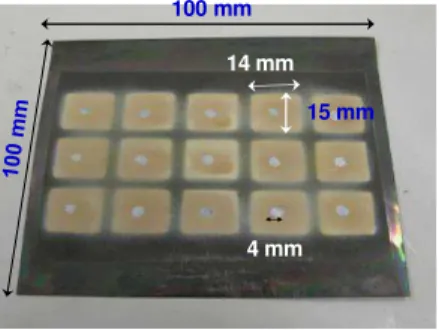
100 mm
14 mm
15 mm
4 mm
Fig. 1 Fifteen FUTs coated onto a 75 µm thick Ti membrane. The PZT-c film thickness is 92 µm. Top silver electrodes have a 4 mm diameter.
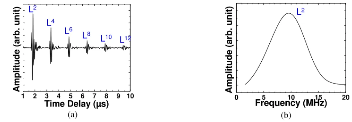
Fifteen FUTs consisting of a 75 µm thick Ti membrane coated with a 92 µm thick PZT-c film and a 10 µm thick silver paste were fabricated and shown in Fig. 1. One of the FUTs, with a modified silver paste top electrode size having a length of 4 mm and a width of 2 mm, was cut and glued onto a steel pipe as shown in Fig. 2a. The glue was cured at 80°C for 90 minutes. The outer diameter (OD) and the wall thickness of the steel pipe were 101 mm and 4.5 mm, respectively. In Fig. 2b ultrasonic pulse/echo measurements at 200°C were taken with an Olympus-Panametrics EPOCH LT pulser/receiver. This particular type of handheld device is used on a daily basis for NDE in industrial settings. The pulse energy used was 100 volts, the lowest available on the EPOCH LT, and the gain used was 16 dB out of the available 100 dB. Figs. 3a and 3b show the measured ultrasonic signals in time and frequency domain, where Ln is the nth trip of the longitudinal echo (L) through the pipe wall thickness. The center frequency and the 6 dB bandwidth of the L2 echo were 9.8 MHz and 8.1 MHz respectively. The signal strength at 200 °C was 8 dB weaker than at room temperature
due to some ultrasonic loss in the glue and steel and the reduced piezoelectric strength of PZT-c film at 200°C. When this FUT was tested with a metal plate, its signal strength was found to be the same as that obtained with a commercial broadband UT which, however, is difficult to use for pipes at 200°C.
101mm FUT 4.5 mm
Steel Pipe
(a) (b)
Fig. 2 (a) One FUT shown in Fig. 1 glued to a steel pipe with an O.D. of 101 mm and a thickness of 4.5 mm, (b) ultrasonic measurement at 200°C. 1 2 3 4 5 6 7 8 9 10 A m p li tu d e ( a rb . u n it ) Time Delay (µs) L2 L4 L6 L8 L10 L12 (a) 0 5 10 15 20 A m p li tu d e ( a rb . u n it ) Frequency (MHz) L2 (b)
Fig. 3 Ultrasonic signals obtained with the experimental setup shown in Fig. 2b; (a) in time domain and (b) L2 in frequency domain.
2.2. Thickness Measurement Accuracy at 200°C
Equation (1) (Equation 19 in [22]) was used to estimate the accuracy in time delay and thickness measurement of the steel pipe tested under the conditions presented in Fig. 2b. The equation takes into account jitter and false peak errors that may arise in delay time estimations that are commonly due to noise, finite window lengths and signal decorrelations resulting from the experimental setup and/or the imperfections in the transducers.
1
1
1
1
1
1
12
2
3
'
2 2 2 1 2 3 2 3 0T
B
B
SNR
SNR
f
t
t
(1)In this equation, f0 is the center frequency, T is the time window length for the selection of L
2
and L4 in Fig. 3a that is required for the cross correlation measurement, B is the fractional bandwidth of the signal, which is the ratio of the signal bandwidth over f0, is the correlation coefficient, SNR1 and SNR2 are the SNR of echoes L2 and L4 respectively, and (∆t - ∆t’) is the standard deviation of the measured time delay (∆t being the true time delay and ∆t’ the measured time delay). Using Equation 1 and the parameters tabulated in Table 1, which characterize this particular brazed FUT, the calculated (∆t - ∆t’) was 2.61 ns. To this valus,we must add an uncertainty of 2 ns due to the digitization resolution and interpolation.
Table 1: Parameters for Equation 1 and digitization resolution
Parameters Values for the FUT
glued on steel pipe
ƒ0 9.8 MHz T 0.32 µs B 0.82 0.94 SNR1 15 dB SNR2 15 dB
)
(
t
t
2.61 ns Digitization resolution (100 MHz) including interpolation 2 nsTotal time delay uncertainty 4.61 ns
VL 5755 m/s
Thickness measurement accuracy 13 µm
The total uncertainty in time delay measurement using interpolation [23] is therefore estimated at 4.61 ns. Since the measured longitudinal velocity VL in the steel pipe using the pulse-echo technique at 200°C was 5755 m/s, the best possible thickness measurement accuracy achievable on this 4.5 mm thick pipe was 13 µm in pulse-echo mode at 200°C. If the sampling rate is increased to more than 100 MS/s, improved thickness measurement accuracy may be obtained.
3. ULTRASONIC PERFORMANCE OF FUTs AS PAW UTs
Integrated UTs (IUTs) have been directly deposited onto the edges of 2 to 6 mm thick Al plates to excite and detect the PAWs operated at up to 150°C [20]. It was also demonstrated that SH PAWs could detect line defects efficiently. However, IUTs require a heat treatment, ideally at temperatures close to 650 °C, which is sometimes detrimental to the component. In such cases, FUTs have an advantage because they can be glued to components, as was illustrated in Section 2. In this study Al plates of 406.mm by 50.8 mm by 2 mm thick will be used for the demonstration.
FUT 25.4 mm 50.8 mm 406.4 mm 146.3 mm 223.5 mm Al plate (Thickness 2mm) D1’ D2’ SH,D1 SH,D2 D1’, D2’: Depth: 1 mm; Width: 1 mm SH,2
Fig. 4 One FUT was glued and two artificial line defects, D1’ and D2’ were made onto a 2 mm thick Al plate for the demonstration of global NDE capability of PAW.
61.7°
FUT
Fig. 5 Zoomed FUT shown in Fig. 4.
In order to generate and receive SH PAWs, an FUT was glued at the side edge near the end of a 2 mm thick Al plate with a length of 406.4 mm and width of 50.8 mm, as shown in Figs. 4 and 5. The glue was cured at room temperature for 24 hours. Two artificial line defects, D1’ and D2’ with 1 mm depth and 1 mm width were made on
this Al plate with respective lengths of 25.4 mm and 50.8 mm. Using mode conversion [19, 20] SH PAWs may be predominantly excited and received [20]. The top rectangular electrode of the FUT shown in Fig. 4 has a height of 2 mm and a width of 25 mm, which define its active area. The chosen mode conversion angle of 61.7° was calculated using the phase matching between the measured extension mode velocity and the S wave velocity of the Al plate.
50 100 150 200 250 300 A m p li tu d e ( a rb . u n it ) Time Delay (µs) SH,D1’ SH,D2’ SH,2 Multiple reflections from D1’ and D2’ (a) 50 100 150 200 250 300 A m p li tu d e ( a rb . u n it ) Time Delay (µs) SH,D1’ SH,D2’ SH,2 Multiple reflections from D1’ and D2’ (b)
Fig. 6 SH PAW signals detecting two artificial line defects, D1’ and D2’ in a 2 mm thick Al plate shown in Fig. 4 at (a) room temperature and (b) 100C.
The measured predominant SH PAW signals at room temperature and at 100°C are shown in Figs. 6a and 6b, respectively. The SH,D1’ and SH,D2’ are the reflected echoes from the artificial line defects D1’ and D2’, respectively and the signal strength of echo SH,D1’ at 100°C is 2.3 dB less than that at room temperature. The echoes between SH,D2’ and SH,2 come from the multiple reflections between D1’ and D2’. It is demonstrated that not only SH PAWs can clearly detect the defects D1’ and D2’ which are 146.3 mm and 223.5 mm away, respectively from the FUT at 100°C, but also travel to the end of the plate and return back to the FUT with good SNR, as indicated by the echo SH,2. The center frequency and bandwidth of echo SH,D1’ at 100°C are 7.9 MHz and 5.3 MHz, respectively. Since the group velocities of the first several SH PAW modes are close to the S wave velocity of the Al plate in the range of FUT excitation frequency [20], the pulse widths of the SH,D1’ and SH,D2’ are narrow. In Fig. 6, SH,2 is the first round trip echo from the FUT to the end of the Al plate. Using the echo SH,2 the calculated group velocity is 3136 m/s which is close to the shear wave velocity 3144 m/s of the Al plate, thus SH,D1’, SH,D2’ and SH,2 are from predominately SH PAWs. This type of wave results in very clean separated echoes for each defect due to the fact that the main generated mode is the SH0 PAW [20], which has no dispersion.
4. ULTRASONIC MEASUREMENTS OF GR/EP COMPOSITES
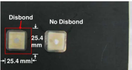
FUTs shown in Fig. 1 can be also used as L wave UTs for the evaluation of Gr/Ep composites. An 8.3 mm thick Gr/Ep composite plate with a stacking sequence of [0/45/0/-45/90/90/-45/0/45/0] x3 was made with an embedded artificial defect consisting of a thin Teflon sheet of 25.4 mm by 25.4 mm. Initially, an ultrasonic C-scan of the Gr/Ep composite sample in a water immersion tank was obtained with a of 19 mm diameter focused transducer of 7.5 MHz center frequency and 152.4 mm a focal length. The scanning step was 0.5 mm in the lateral directions. Fig. 7 shows the obtained ultrasonic C-scan image near the Teflon insert region indicated as a disbonded region. Then two FUTs similar to the one shown in Fig. 1 with a top electrode area of 4 mm diameter were glued at two locations of the composite plate, with and without a disbond, as shown in Fig. 8. The glue was cured at room temperature for 24 hours. Since the operation temperature of these aerospace composites normally ranges from -60C to 100C, both PZT-c thick film FUTs, together with the glue, were tested and found to survive thermal cycles from -60C to 100C.
Disbond
No Disbond
25.4 mm 25.4 mm
Disbond
No Disbond
25.4 mm 25.4 mm
Fig. 8 Two FUTs glued onto the Gr/Ep composite plate of Fig. 7 above regions with and without a disbond.
At room temperature the measured ultrasonic signals obtained with these two FUTs are shown in Fig. 9a and 9b, respectively at the locations without and with a disbond. Ln is the nth round trip echo through the thickness of the Gr/Ep composite and LDn is the nth round trip echo from the FUT to the disbond region. The center frequency and 6 dB bandwidth of the L1 and LD1 echo are 8.9 MHz and 2.5 MHz, 9.4 MHz and 5 MHz, respectively.
5 10 15 20 A m p li tu d e ( a rb . u n it ) Time Delay (µs) L1 L2 (a) 5 10 15 20 A m p li tu d e ( a rb . u n it ) Time Delay (µs) LD1 LD2 (b)
Fig. 9 Measured ultrasonic signals in time domain at room temperature at a location (a) without and (b) with disbond using the FUTs shown in Fig. 8.
5. NON-CONTACT APPROACH
In order to achieve NDE and SHM of rotating components, non-contact ultrasonic measurement approaches are desired. In this study an induction based method [20, 21] is used. Here FUTs replace the IUTs reported in [20]. The Al sample shown in Fig. 4 and the Gr/Ep sample with FUTs shown in Fig. 8 are chosen for demonstration purposes. Firstly a flat coil made of a thin lacquered wire served as a main component for induction coupling. The two ends of this coil were connected to the top electrode of the FUT and the Ti membrane which served as the bottom electrode of the FUT. Directly on top of the coil connected to the FUT, another flat coil was connected to the coaxial cable of the pulser/receiver.
Fig. 10 shows the measured SH PAW signals along the Al sample shown in Fig. 4 but using the induction based non-contact method. The separation distance between the two coils was 10 mm. The two artificial line defects can be detected. The center frequency and bandwidth of the SH,D1’ echo at room temperature are 4.4 MHz and 3.6 MHz, respectively. In comparison with the contact method shown in Fig. 6a, the non-contact method shown in Fig. 10 required a receiver gain 20 dB higher than that for the contact configuration.
50 100 150 200 250 300 A m p li tu d e ( a rb . u n it ) Time Delay (µs) SH,D1’ SH,D2’ SH,2 Multiple reflections from D1’ and D2’
Fig. 10 Ultrasonic SH PAW signal in time domain obtained using an FUT shown in Fig. 4 with the non-contact configuration at room temperature. 5 10 15 20 A m p li tu d e ( a rb . u n it ) Time Delay (µs) L1 L2 (a) 5 10 15 20 A m p li tu d e ( a rb . u n it ) Time Delay (µs) LD1 LD2 (b)
Fig. 11 Measured ultrasonic signals in time domain at room temperature at a location (a) without and (b) with disbond using the FUTs shown in Fig. 8 and an inductive non-contact method.
When this non-contact method is applied with the two FUTs shown in Fig. 8, the measured room temperature ultrasonic signals at the location without and with the disbond are presented in Figs. 11a and 12b, respectively. The center frequency and 6 dB bandwidth of the L1 and LD1 echoes are 2.9 MHz and 2.1 MHz, 2.9 MHz and 1.8 MHz, respectively. The separation distance between the two coils was 10 mm. The ultrasonic signals achieved were again 20 dB weaker with the non-contact approach than with the contact method. It is noted that the tuning of the electrical impedance matching between the FUTs and the size, diameter and number of turns of coils have not been optimized. Therefore the measured ultrasonic frequencies of the echoes shown in Figs.10 and 11 are significantly affected by the electrical impedance of the coil. The optimization of the coils with respect to the pulser/receiver and the FUTs will be performed in the future.
6. CONCLUSIONS
FUTs were presented for non-destructive evaluation (NDE) and structural health monitoring (SHM) purposes. They can be glued on-site and the glue serves as the ultrasonic couplant between the FUT and the object for inspection. These FUTs consist of an approximately 70 µm thick piezoelectric PZT-c film made by a sol-gel spray technique coated on a 75 µm thick Ti membrane. Such an FUT with a center frequency at around 9.8 MHz was glued onto a steel pipe of 101 mm in diameter and 4.5 mm in wall thickness and operated at up to 200°C. The pipe thickness measurement accuracy at 200°C was estimated to be 13 µm.
FUTs centered at about 6.5 MHz were also glued on the side edge of a 2 mm thick aluminum (Al) plate to generate and receive predominantly SH PAWs at temperatures up to 100°C. Two line defects with 1 mm in width and 25.4 mm and 50.8 mm in depth and length, respectively, located at distances of about 146.3 mm and 233.5 mm respectively from the FUT location were fabricated and shown to be detectable using SH PAWs. FUTs were also glued onto an 8.3mm thick Gr/Ep composite plate. An embedded artificial disbond was easily detected by FUT. An induction type non-contact method for the evaluation of Al plates and Gr/Ep composites using FUTs was also demonstrated. Such a non-contact technique may be desirable for SHM and NDE of rotating components.
ACKNOWLEDGMENT
Financial support from the Natural Sciences and Engineering Research Council of Canada for K.-T. Wu and J.-L. Shih and technical assistance from Jacques Tatibouët and I.-H. Liu are acknowledged.
REFERENCES
:
[1] Birks, A.S., Green, R.E., Jr. and McIntire, P., “Nondestructive Testing Handbook”, 2nd ed., vol.7: Ultrasonic Testing, ASNT, pp.569-587, 1991.
[2] Moore, P.O., Workman, G.L. and Kishoni, D., “Nondestructive Testing Handbook”, 3rd ed., vol.7: Ultrasonic Testing, ASNT, pp.427-474, 2007.
[3] Karasawa, K., Izumi, M., Suzuki, T., Nagai, S., Tamura, M. and Fujimori, S., “Development of under-sodium three-dimensional visual inspection technique using matrix-arrayed ultrasonic transducer,” Journal of Nuclear Science and Technology, vol. 37, no. 9, pp. 769-779, 2000.
[4] Kelly, S.P., Atkinson, I., Gregory, C. and Kirk, K.J., “On-line ultrasonic inspection at elevated temperatures”, Proc. IEEE Ultrasonics Symp., pp. 904-908, 2007.
[5] Ihn, J.-B. and Chang, F.-K., “Ultrasonic Non-destructive Evaluation for Structure Health Monitoring: Built-in Diagnostics for Hot-spot Monitoring in Metallic and Composite Structures”, Chapter 9 in Ultrasonic Nondestructive Evaluation Engineering and Biological Material Characterization, T. Kundu, Ed. Florida: CRC Press, 2003.
[6] Giurgiutiu, V., “Structural Health Monitoring with Piezoelectric Wafer Active Sensors”, Elsevier, N.Y., 2007. [7] Dalton, R.P., Cawley, P. and Lowe, M.J.S., “The potential of guided waves for monitoring large areas of metallic
aircraft structure”, J. Nondestructive Evaluation, vol.20, pp.29-46 , 2001.
[8] Gentzen, V., Choi, Y.-T., Purekar, A.S. and Wereley, N.M., “Experiment Detection and Quantitative Interrogation of Damage in a Jointed Composite Structure”, J. Int. Mat. System and Struct., vol.21, pp.275-283, 2010.
[9] Salas, K.I. and Cesnik, C.E.S., “Guided Wave Structural Health Monitoring Using CLoVER Transducers in Composite Materials”, Smart Materials and Structures, vol.19, pp.1-25, 2010.
[10] Kirk, K.J., McNab, A., Cochran, A., Hall, I. and Hayward, G., “Ultrasonic arrays for monitoring cracks in an industrial plant at high temperatures”, IEEE Trans. Ultrason., Ferroelect., Freq. Contr., vol.46, no.2, pp. 311-318, 1999.
[11] Kazys, P., Voleisis, A., and Voleisiene, B., “High temperature ultrasonic transducers: a review”, Ultragarsas, vol.63, pp.7-17, 2008.
[12] Kobayashi, M. and Jen, C.-K., “Piezoelectric thick bismuth titanate/PZT composite film transducers for smart NDE of metals”, Smart Materials and Structures, vol.13, 951-956, 2004.
[13] Kobayashi, M., Jen, C.-K., Bussiere, J.F. and Wu, K.-T., “High temperature integrated and flexible ultrasonic transducers for non-destructive testing”, NDT&E Int., vol.42, no.2, pp.157-161, 2009.
[14] Park, J.-M., Kong, J.-W., Kim, D.-S. and Yoon, D.-J., “Nondestructive damage detection and interfacial evaluation of single-fibers/epoxy composites using PZT, PVDF and P(VDF-TrFE) copolymer sensors”, Composites Science and Technology, vol. 65, pp. 241-256, 2005.
[15] Parr, A.C.S., O’leary, R.L. and Hayward, G., “Improving the thermal stability of 1-3 piezoelectric composite transducers”, IEEE Trans. Ultrason., Ferroelect., Freq. Contr., vol. 52, no. 4, pp. 550-563, 2005.
[16] Harvey, G., Gachagan, A., Mackersie, J.W., McCunnie, T. and Banks, R., “Flexible ultrasonic transducers incorporating piezoelectric fibers”, IEEE Trans. Ultrason. Ferroelect. Freq. Control, vol.56, no.9, pp. 1999-2009, 2009.
[17] Kobayashi, M., Jen, C.-K. and Lévesque, D., “Flexible ultrasonic transducers,” IEEE Trans. Ultrason., Ferroelect., Freq. Contr., vol.53, no.8, pp.1478-1485, 2006.
[18] Barrow, D.A., Petroff, T.E., Tandon, R.P. and Sayer, M., “Characterization of thick lead zirconate titanate films fabricated using a new sol gel based process”, J. Appl.. Phys., vol. 81, no. 2, pp. 876-881, 1997.
[19] Jen, C.-K., Ono, Y. and Kobayashi, M., “High temperature integrated ultrasonic shear wave probes”, Applied Phys. Lett., vol.89, 183506, 2006.
[20] Wu, K.-T., Kobayashi, M. and Jen, C.-K. “Integrated high temperature piezoelectric plate acoustic wave transducers using mode conversion”, IEEE Trans. Ultrason., Ferroelect., Freq. Contr., vol.56, 1218-1224, 2009.
[21] Greve, D.W., Sohn, H., Yue, C.P. and Oppenheim, I.J., “An inductively coupled lamb wave transducer”, IEEE Sensors J., vol.7, pp.295-301, 2007.
[22] Walker, W.F. and Trahey, G.E., “A fundamental limit on delay estimation using partially correlated speckle signals,” IEEE Trans. Ultrason. Ferroelect. Freq. Control, vol.42, no. 2, pp.301-8, 1995.
[23] Aussel, J.-D. and Monchalin, J.-P., “Precision laser-ultrasonic velocity measurement and elastic constant determination,” Ultrasonics, vol.27, no.3, pp.165-177, 1989