Base plate in bending and
anchor bolts in tension
František Wald
Czech Technical University, Faculty of Civil Engineering, Prague, Czech Republic
Zdeněk Sokol
Czech Technical University, Faculty of Civil Engineering, Prague, Czech Republic
Jean-Pierre Jaspart
Université de Liège, Institut du Génie Civiel Départemant MSM, Belgium
This paper describes the behaviour of the base plate in bending and the anchor bolts in tension, which are the major components of a base plate connection. An analytical model has been derived to predict the component characteristics – the resistance and the stiffness. A description is given of how the behaviour is influenced by contact between the base plate and the concrete surface. The presented analytical model has been verified by tests and a finite element simulation.
Key words: Steel structures, column bases, component method, Eurocode 3, anchor bolt
1
Introduction
The base plate connections have a different configuration compared to the beam to column end plate connections. Thick base plates are designed to transfer compression forces into the concrete block and are stiffened by the column and the additional stiffeners when necessary. The anchor bolts are longer compared to the bolts used in end plates due to presence of washer plates and grout, thick base plate and the part embedded in the concrete block. The length of the anchor bolts allows deformation and separation of the base plate when the anchor bolts are loaded in tension. Different behaviour should be considered when strength, stiffness and rotational capacity of the base plate loaded by bending moment have to be predicted, see [1].
The column base stiffness is in particular influenced by behaviour of the tension part of the base plate, see [2]. Published models of the column base loaded by bending moment
include different levels of modelling of the tension part of the column base from very simple models to very complex solution, see [3]. The knowledge of the behaviour of the end plates in beam to column connections was extended in [4] by most recent models, see [5] and [6]. For modelling of structural steel connections was adopted a component method, see [7]. In this method, the connection characteristics are composed from characteristics of several components, whose behaviour can be easily described by simple models. The base plate is represented by the following basic components: base plate in bending, anchor bolt in tension, base plate in compression, concrete block in compression, column flange in compression and base plate in shear. The modelling of the column base with the base plate using component method gives simple and accurate prediction of the behaviour. The most important advantage is the separation of modelling of the each component response, see [8].
2
Beam Model of the T-stub
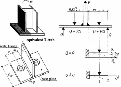
When the column base is loaded by the bending moment, the anchor bolts in the tensile zone are activated to transfer the applied force. This results in elongation of the anchor bolts and bending of the base plate [9]. The failure of the tensile zone could be caused by yielding of the plate, failure of the anchor bolts, or combination of both phenomena.
Figure 1: The T-stub, anchor bolts in tension and base plate in bending, assumption of acting forces and deformations of the T-stub in tension
Model of the deformation curve of the T-stub of base plate is based on similar assumptions which are used for modelling of the T-stub of beam-to column joints, see [10]. Two cases should be considered for the column bases. In the case the bolts are flexible and the plate is stiff, the plate is separated from the concrete foundation. In the other case, the edge of the plate is in contact with the concrete resulting in prying of the T-stub and the bolts are loaded by additional prying force Q, which is balanced by the contact force at the edge of the T-stub, see Figure 1. Stiffness coefficient of the components is derived for both cases. When there is no contact of the T-stub and the concrete foundation, the deformation of the bolts and the T-stub are given by
b b s F L A E δ = 2 , (1)
where F is the tensile force in the bolt and
3 2 3 p F mEI
δ = . (2)
The bolt stiffness coefficient for the component method is defined according to [4]
2,0 s b b b F A k E L = = δ , (3)
and the stiffness coefficient of the T-stub is
3 , 3 eff ini p l t k m = . (4)
The stiffness coefficient T-stub without contact between the plate and the concrete foundation is ( ) T p b F k E = δ + δ , (5)
which can be re-written using stiffness coefficients of the components b p T b p k k k k k = + . (6)
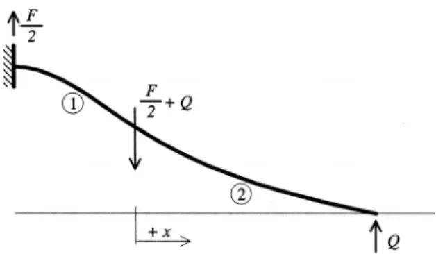
When there is contact between the plate and the concrete, beam theory is used to derive the model of the T-stub. The deformed shape of the flange is derived from the following differential equation, see Figure 2,
E Iδ = − ′′ M (7)
Figure 2: The beam model of the T-stub
Writing the above equation for the part (2) of the T-stub leads to
2 ( )
E Iδ =′′ Q x n− (8)
and the equation for the part (1) close to the centreline of the T-stub is
1 2F
E Iδ = −′′ x Qn− (9)
The following boundary conditions should be considered when the equations (8) and (9) are solved:
zero rotation at centreline of the T-stub (x = -m), zero deformation at the edge of the plate (x = n),
equal rotation of both parts at the bolt location (x = 0), equal deformation of both parts at the bolt location (x = 0).
The equation for the deflection on the part (1) is
3 2 2 1 2 3 2 ( 2 ) 2 b (1 ) s n L I F x x m x m x E I A ⎡ κ ⎤ δ = ⎢ − − − + − κ⎥ ⎢ ⎥ ⎣ ⎦ (10)
and for the part (2) of the T-stub
3 2 2 2 2 3 2 ( 2 ) 2 b (1 ) s x n L I F m x x mx E I A ⎡κ κ ⎤ δ = ⎢ − − − + − κ⎥ ⎢ ⎥ ⎣ ⎦, (11)
where the coefficient κ, which represents the relative stiffness of the base plate and the anchor bolts, is defined as
2 3 2 2 3 2 3 3 b s s s b L I m n A n A mn A L I − κ = + + . (12)
In the above equations, the m and n are dimensions of the T-stub defined at the Figure 1 and Lb and As are bolt length and the net area of the bolt respectively. The second moment of area of the base plate cross-section is defined as
3 , 1 12 eff ini
I= l t (13)
In addition, the formula for the prying force can be derived from the above equations
2 2 3( 2 ) 2 2 (3 ) 3 2 b b m n A L I F F Q n A m n L I − = = κ + + (14)
When contact between the stub and concrete surface is present, the deformation of the T-stub is given by the formula derived from equation (10)
3 2 2 4 ( 1) (4 3) 16 ( ( 3)) p b T p p b k k F E k k k λ + + λ λ + δ = + λ λ + (15)
where the parameters λ and β are defined below
λ = n / m (16)
β = t / m . (17)
The equation (15) is used to derive the stiffness coefficient of the T-stub with contact between the plate and the concrete foundation
2 3 2 16 ( ( 3)) 4 ( 1) (4 3) p p b T T p b k k k E k F k k + λ λ + = = δ λ + + λ λ + . (18)
Figure 3: The boundary of the prying action
The boundary between the cases with and without contact, see Figure 3, can be evaluated from equation (14) by setting the prying force equal to zero
2 2
b L m n
I = A . (19)
The expression (13) is substituted into (19) and the limiting bolt length can be evaluated from the boundary
2 ,lim 3 , 6 s b eff ini m n A L l t = (20)
The effective length of the T-stub for elastic behaviour is assumed
, 0,85
eff ini eff
l = l (21)
and n is taken equal to 1,25 m for simplification, see [7]. The boundary is represented as the limiting bolt length
3 ,lim 3 8,82 s b eff m A L l t = (22)
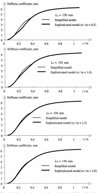
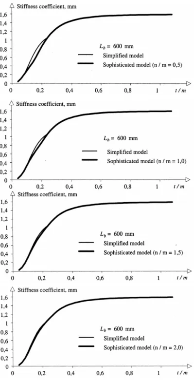
The above estimation of the boundary introduced an error into the prediction of the stiffness coefficient. The accuracy of the simplified approach is shown in the Figures 4b, 4c, and 4d. Three calculations with the T-stub are presented. The T-stub characteristics areleff = 458,333 mm, As= 480 mm², m = 50 mm andLb= 150 mm (short anchor bolts, Figure 4b),
b
L = 300 mm (moderate anchor bolts, Figure 4c), Lb= 600 mm (long anchor bolts, Figure 4d), while the n/m ratio takes the following values: 0,5; 1,0; 1,5 and 2,0.
The boundary between "prying" and "no prying" is computed by means of formulae (20) and (22) for the theoretical and simplified models respectively.
Figure 4b: Comparison between the theoretical and simplified models of the stiffness coefficient of the T-stub for variable thickness ratio t / m, Lb= 150 mm
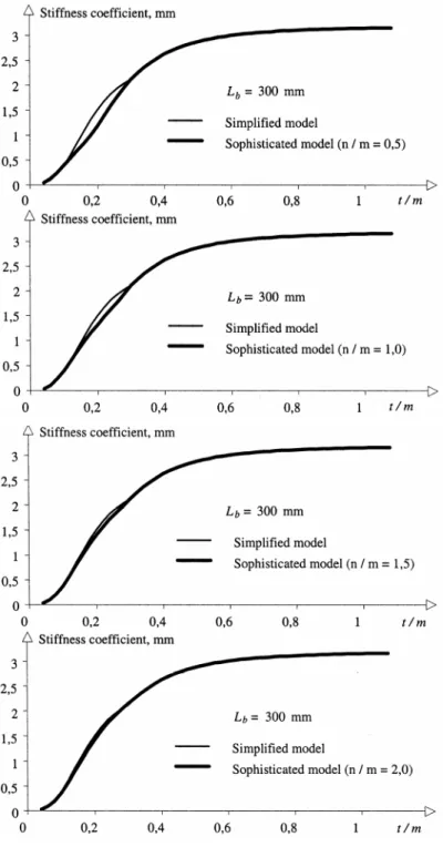
Figure 4c: Comparison between the theoretical and simplified models of the stiffness coefficient of the T-stub for variable thickness ratio t / m, Lb= 300 mm
Figure 4d: Comparison between the theoretical and simplified models of the stiffness coefficient of the T-stub for variable thickness ratio t / m, Lb= 600 mm
3
Stiffness coefficients
The component method adopted in Eurocode 3 [4] allows the prediction of the base plate stiffness. The boundary is given by
3 , 3 8,82 eff ini s b l t A L ≥ m (23)
When the above condition is satisfied, contact will occur and prying forces will develop. However, it is assumed the components are independent in this case, see [7], and the stiffness coefficients of the components are
3 3
,
, 3 3 3
0,85 eff ini eff p EC l t l t k m m = = (24) , 3 1,6 s b EC b A k L = (25)
When there is no prying, the condition (23) changes to
3 , 3 8,82 eff ini s b l t A L ≤ m (26) 3 3 , ,* 3 3 0, 425 2
p eff ini eff
p p F l t l t k E m m = = = δ (27) ,* p 2,0 s b b b F A k E L = = δ (28)
The stiffness coefficient of the base plate in bending (24) or (27) and bolts in tension (25) or (28) should be composed into the stiffness coefficient of the T-stub
, ,
1 1 1
T p i b i
The influence of the washer plate on the deformation of base plate is studied in [8]. It is shown, that the stiffness is not influenced by an additional plate and the cover plate may be neglected for the practical design.
4
Design Resistance
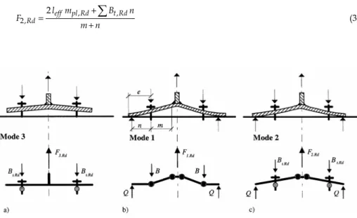
In the Eurocode 3 [4], three collapse mechanisms of the T-stub are derived. These collapse modes can be used for T-stubs in contact with the concrete foundation. The design resistance corresponding to the collapse modes is the following:
Mode 3 - bolt fracture, see Figure 5a,
3,Rd t Rd,
F =
∑
B (30)Mode 1 - plastic mechanism of the plate, see Figure 5b,
, 1, 4 eff pl Rd Rd l m F m = (31)
Mode 2 - mixed failure of the bolts and the plate, see Figure 5c,
, , 2, 2eff pl Rd t Rd Rd l m B n F m n + = +
∑
(32)The design resistanceFRdof the T-stub is derived as the smallest value obtained from the expressions (30) to (32) 1, 2, 3, min( , , ) Rd Rd Rd Rd F = F F F (33)
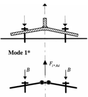
In case when there is no contact of the T-stub and the concrete foundation the failure results either from the anchor bolts in tension (Mode 3) or from yielding of the plate in bending, see Figure 6. However, the collapse mode is different from the plastic mechanism of the plate with contact (Mode 1) and only two hinges develop in the T-stub. This failure is not likely to appear in the beam-to-column joints and beam splices because of the small deformation of the bolts in tension. This particular failure mode is named Mode 1*, see Figure 6.
Figure 6: The Mode 1* failure
The resistance corresponding to Mode 1* is , 1*, 2 eff pl Rd Fd l m F m = (34)
Large base plate deformation can be observed the Mode 1 * failure, which may finally result in the contact between the concrete foundation and the edges of the T-stub, i.e. in the prying forces. Further loads may therefore be applied to the T-stub until failure is obtained through Mode I or Mode 2. However, to reach these collapse modes, large deformations of the T-stub are observed, which is not acceptable for the design. The additional resistance which arises between Mode 1 * and Mode 1 or Mode 2, see Figure 7, is therefore
disregarded and formula (34) is applied despite the discrepancy which could result from the comparisons with some experimental results [16].
As a conclusion, the design resistance of the T-stub in cases when no prying forces develop is taken equal to
1*, 3,
min( , )
Rd Rd Rd
F = F F . (35)
The influence of cover plate used for strengthening of the base plate may be considered [4]. It is applicable to the collapse mode I where the bending moment resistance of the cover plate is introduced [9] ,1 , , 1, (4 2 ) eff pl Rd bp Rd Rd l m m F m + = , (36) where 2 , , 0 4 bp y bp bp Rd M t f m = γ , (37) and , y bp
f is the yield stress of the cover plate,
bp
5
Effective Length of the T-stub
Two groups of yield line patterns called circular and non-circular yield lines are
distinguished in Eurocode 3 [4], see Figure 8a. The major difference between circular and non-circular patterns is related to contact between the T-stub and rigid foundation. The contact may occur only for non-circular patterns and prying force will develop only in this case. This is considered in the failure modes as follows:
Mode 1
The prying force does not have influence on the failure and development of plastic hinges in the base plate. Therefore, the formula (31) applies to both circular and non-circular yield line patterns.
Mode 2
First plastic hinge forms at the web of the T-stub. Plastic mechanism is developed in the base plate and its edges come into contact with the concrete foundation. As a result, prying forces develop in the anchor bolts and bolt fracture is observed. Therefore, Mode 2 occurs only for non-circular yield line patterns, which allow development of prying forces.
Mode 3
This mode does not involve any yielding of the plate and applies therefore to any T-stub. In the design procedure, the appropriate effective length of the T-stub should be used
for Mode 1: leff,1= min( leff cp, ; leff np, ) (38)
for Mode 2: leff,2=leff np, (39)
and the design resistance of the T-stub is given by the formula (33).
a) Circular pattern,leff cp, b) Non-circular pattern,leff np, Figure 8: The yield line patterns
Concerning Mode 1* failure, both circular and non-circular patterns have to be taken into consideration. Tables 1 and 2 indicate the values ofl for typical base plates in cases with eff and without contact. See Figures 9 and 10 for the used symbols.
6
Anchor Bolts
The following anchor bolt types represent commonly used fixing to the concrete foundation: hooked bars for light anchoring, cast-in-place headed anchors and anchors bonded to drilled holes, see Figure 11. When it is necessary to transfer a big force, more
Table 1: The effective length leffof a T-stub of the base plate with two bolts inside the flanges
Prying case No prying case
1 2 (4 1,25 ) l = α −m m+ e l1= α −2 m (4m+1,25 )e 2 2 l = π m l2= π 4 m ,1 min( ; )1 2 eff l = l l leff,1=min( ; )l l1 2 ,2 1 eff l = l leff,2= l1
Table 2: Effective length l of a T-stub of base plate with for bolts eff
Prying case No prying case
1 4 x 1,25 x l = m + e l1=4mx+1,25ex 2 2 x l = πm l2= π2 mx 3 0,5 p l = b l3=0,5bp 4 0,5 2 x 0,625 x l = w+ m + e l4=0,5w+2mx+0,625ex 5 2 x 0,625 x l = +e m + e l5= +e 2mx+0,625ex 6 x 2 l = πm + e l6= πmx+4e 7 x l = πm + p l7= π2( mx+ p) ,1 min( ; ; ; ; ; ; )1 2 3 4 5 6 7 eff l = l l l l l l l leff,1=min( ; ; ; ; ; ; )l l l l l l l1 2 3 4 5 6 7 ,2 min( ; ; ; )1 3 4 5 eff l = l l l l leff,2=min( ; ; ; )l l l l1 3 4 5
Figure 9: The effective length l of eff Figure 10: The effective length l of a T-stub of eff a T-stub of the base plate with two bolts the base plate with four bolts
Figure 11: Basic types of anchoring; a) cast-in-place, b) undercut, c) adhesive, d) grouted, e) expansion, f) anchoring to grillage beams
expensive anchoring systems such as grillage beams embedded in concrete are designed. The models of the design resistance of the anchoring compatible with Eurocode have been prepared for the short anchoring used in concrete structures [12] and are also applicable to long anchors used for steel structures.
The resistance of the anchoring is based on the ultimate limit state concept. The collapse of anchoring (pullout of the anchor, failure of the concrete, ...) should be avoided and collapse of anchor bolts is preferred. This avoids brittle failure of the anchoring. For seismic areas, the failure of the column base should occur in the base plate rather than in the anchor bolts [13]. The plastic mechanism in the plate ensures ductile behaviour and dissipation on energy.
For a single anchor, the following failure modes have to be considered:
• The pull-out failureNp Rd, ,
• The concrete cone failureNc Rd, ,
Similar verification is required for group of anchor bolts.
The detailed description of the formulas for design resistance of various types of fastening is included in the CEB Guide [12]. For calculation of the anchoring resistance, the
tolerances of the bolt position recommended in standard [14] should be taken into account according to Eurocode 3 [4]. This makes the prediction of resistance and stiffness more complicated which is not convenient in the practical design. The study [9] shows small sensitivity of predicted stiffness and resistance to bolt tolerances.
In case of embedded anchor bolts, the effective length of the boltLbconsists of the free length L and effective embedded lengthbf Lb=Lbf +Lbe, see Figure 12.
Figure 12: The effective length of the anchor bolt
The headed anchor bolt can be used as a reference for modelling of the embedded anchor bolts that are used in steel structures. The deformation of the anchor bolt δ consists from elongation of the boltδ , deformation of the concrete coneb δ and elongation due to bolt c head deformation δ . h
b c h
δ = δ + δ + δ . (40)
The prediction of the bolt deformation can be simplified taking into account only the bolt elongation. The prediction of embedded length of typical anchor bolts is based on assumption of the distribution of the bond stress [15]. The relative displacement δ between the surface of the concrete foundation and the embedded bar subjected to tensile force has been observed experimentally [11]. Based on these experimental observations, the distance
t
L , at which the tensile stress in the bolt decreases to zero can be approximated to 24 d. In the calculations of the stiffness properties of the anchor bolts in tension, constant stress in
the bolt σ is assumed on the embedded lengthLbe, see Figure 13b). The deformation of the bolt δ is expressed as be s BL E A δ = . (41)
Whenσ designates the bond stress between the concrete and the embedded bolt, the bx axial
stress σ along the bar is equal to
0 4 x bx x σd dx σ = σ −
∫
, (42)Figure 13: Bond stress distribution for long embedded bar
The stress in the bolt of lengthLemis
0 4 t L bxdx d σ σ =
∫
. (43)0 4 t L bx x E dx d σ ε =
∫
. (44) and 2 0 0 4 t t t L L L x bx x dx dx d E δ = ε∫
=∫ ∫
σ (45)Whenσ is constant and independent of x, see Figure 13b, the elongation of the bolt is bx 2
2 b emL d E σ
δ = (46)
Assume the lengthLemis proportional to the bolt diameter d and the lengthLt≅24d, then
4 b t d L σ σ = (47)
and the elongation of the bolt at the concrete surface is
2 2 2 4 2 b em em em t L d L L d E d L E E σ σ σ δ = = = , (48) b t F L E A δ = , (49) finally 12 3 em be L L = = d. (50)
When linear distribution of the bond stress is assumed as shown in Figure 14, the bolt elongation is equal to 2 0 2 3b em L d E σ δ = (51)
Figure 14: Linear model of bond Figure 15: Non-linear distribution stress for long embedded bar of the bond stress
In case of the elongation b' is proportional to the bolt diameter d
0 2 b em d L σ σ = , (52)
it is possible to express the effective embedded length
24 8
3 3
em
be L d
L = = = d (53)
Non-linear distribution of the bond stress using cubic parabola is assumed, see Figure 15, and the shape can be estimated by
2 0 2 5b t L d E σ δ ≅ (54)
The equation can be rewritten assuming 0 proportional to d for conservative value of the effective embedded length
24 4,8 5t 5
be L d
Analytical prediction of the elongation of embedded anchor bolts is sensitive to
assumption of the distribution of the bond stress along the anchor bolt. The FE sensitivity study was focused on influence of the length of the anchor bolt and the headed plate on elastic deformations at the concrete surface, see Figure 16. The sensitivity study was based on experiments [16] and [17]. Node to surface contact elements are used for modelling of the bond stress.
Based on this study, the effective embedded length of bolts with regular surface can be predicted asLbe≅8d. The stress is developed on length equal to 24 d, which may be expected as a boundary length of the anchoring by long bolts. This length is reduced by the headed plate. The anchor bolt area can be taken as the net areaAsto simplify the design.
Figure 16: A quarter of FE mesh for simulation of the anchor bolt, see test [16], bolt is connected by node to surface contact elements, development of bond stress
7
Validation
Special set of experiments with components was carried out at Czech Technical University in Prague to evaluate a prediction of its behaviour, see [16] and [17]. In total, 4 pull-out tests with M24 embedded anchor bolts were performed, see Figures 17 and 18. The only variable for these tests was the concrete quality of the foundation. For all the tests, the collapse of the thread was observed. The tests show good agreement with the proposed model for the anchor bolt stiffness.
Figure 17: Comparison of the proposed model to experiments with the anchor bolts [17],fck= 40,1 MPa
Figure 18: Comparison of the proposed model to experiments with the anchor bolts [16],fck= 33,3 MPa
The experimental programme with T-stubs in tension consists of twelve tests [16]. It was focused on evaluation of prying effect and resistance and stiffness of the T-stub. For this purpose, the base plate thickness and the bolt pitch were the variable parameters, the other characteristics were constant for all specimens. Six specimens with thick base plate (t = 20 mm) and six with thin base plate (t = 12 mm) were tested. The bolt pitch 110 mm, 140 mm and 170 mm was used for both plate thickness resulting in dimension of the T-stub m = 32,52 and 67 mm, n = 40 mm, see Figure 19. The same M24 anchor bolts and concrete foundation 550 x 550 x 550 mm as in pull-out tests W13 / W14 were used, see Figure 18.
Figure 19: The test specimen for the experiments with the T-stub
The pictures show the test results of the T-stub with the bolt pitch 110 mm and the different base plate thickness. The comparison of the complex and simplified calculations to the experimental results is included. The calculated resistance of specimens with the thin base plate is the same for both models and is in good agreement with the experiments see Figure 21. The combination of the plate mechanism and breaking of the anchor bolts caused the collapse of both specimens, which corresponds to Mode 2 of the design model. The resistance predicted for the specimens W97-01 and W97-02 (thick base plate) is different for complex and simplified models, see Figure 20. According to the simplified model, there is prying of anchor bolts, which results in higher resistance. The complex model predicts no prying of the anchor bolts, which corresponds to the experimental observations. There were no plastic hinges observed in the base plate during the
experiment and the resistance of anchor bolts limits the resistance of the T-stub. However, the collapse was not reached because of the limitation of the load cell. The predicted stiffness is in a good agreement for all tests.
Four tests with increased bolt pitch were performed, see Figures 22 and 23. The prying of the anchor bolts occurred for specimens with thin and thick base plates, which was predicted by complex and simplified prediction models. There is good agreement between the experimental and calculated resistances and stiffness.
Development of two plastic hinges in the base plate of the specimens W97-03 and W97-04 (with thick base plate) was observed during the experiment see Figure 22, but the anchor bolts of the specimens finally collapsed. The specimens with thin base plate collapsed when four plastic hinges created in the base plate. However, the testing was stopped because large uplift (about 8 mm) was achieved. The experiment W97-07, see Figure 23, was interrupted by splitting failure of plain concrete block.
The last four specimens with the largest bolt pitch 170 mm performed similar behaviour during the test. High influence of prying of the anchor bolts was observed, which lead to
Figure 20: The load deflection diagram of experiments W97-01 and W97-02, plate thickness 20 mm
combined collapse of the anchor bolts and the yielding of the base plate where four plastic hinges created. There was only difference on deformation capacity of the T-stubs. The specimens W97 -11 and W97 -12 with thick base plate, see Figure 24, allowed uplift about 9 mm followed by collapse of anchor bolts. The specimen W97 -09 collapsed by splitting failure of plain concrete block, collapse ofW97-10 was not reached, see Figure 25. However, the uplift of both specimens was about 20 mm. The bending and the bearing of the anchor bolts were also observed at the extremely high deformations but it did not have an influence on the collapse.
Figure 22: The load deflection diagram of experiments W97-03 and W97-04, plate thickness 20 mm
8
Conclusions
• The paper describes the background of model behaviour of the basic components of column bases: the base plate in bending and the anchor bolts in tension. The component method for prediction of stiffness and resistance of the column bases loaded by an axial force and a bending moment was implemented into the Eurocode 3 during the conversion from ENV document into EN document, see [19].
Figure 24: The load deflection diagram of experiments W97-11 and W97-12, plate thickness 20 mm
• Length of the bolts in the T-stub is the major difference between T-stubs representing the base plates and T-stubs for end plates of beam to column connections.
• The boundary of behaviour of the T-stub with and without contact of the base plate and the concrete surface can be predicted by simple analytical model with good accuracy. The resistance and stiffness of the component is calculated for both cases by complex and simplified models. The accuracy of the simplified model is shown on the comparison to the complex model and verified on the tests.
• The effective embedded length of the anchor bolt is the most important parameter for the base plate stiffness prediction. The effective length can be estimated asLbe≅8d for typical embedded anchor bolts with regular bolt surface.
Acknowledgement
Within the framework of the European Project COST C1 (Semi-rigid behaviour of civil engineering structural connections) and the Technical Committee 10 of ECCS (European convention for constructional steelwork) an ad-hoc working group prepared a background document for Eurocode 3. Members of this group were: D. Brown, SCI London; A.M. Gresnigt, TU Delft; J.P. Jaspart, University of Liege; Z. Sokol, CTU in Prague; J.W.B. Stark, TU Delft; C.M. Steenhuis, TU Eindhoven; J.C. Taylor, SCI London; F. Wald, CTU in Prague (Convenor of the group) and K. Weynand, RTWH Aachen. The work at this contribution has been supported by grant MSM 6840770005.
References
[1] Treiberg, T.: Pelarfot, Base Plates, in Swedish, Staalbyggnadsinstitutet, Pub. 101, Stockholm 1987.
[2] Akiyama H.: Seismic Design of Steel Column for Architecture. in Japanese, Gibodoskupan, Tokyo 1985.
[3] Melchers R. E.: Modelling of Column-Base Behaviour. In Connections in Steel Structures, Behaviour, Strength and Design, Proceedings, ed. Bjorhovde R., Brozzetti J., Colson A., Elsevier Applied Science, London 1987, pp. 150-157.
[4] Eurocode 3, ENV -1993-1-1, Design of Steel Structures -General Rules and Rules for Buildings. CEN, Brussels 1992; including Part 1.1, A2: Design of Steel Structures- General Rules and Rules for Buildings, Annex J, European Pre-norm, CEN, Brussels 1998.
[5] Zoetemeijer, P.: Summary of the Researches on Bolted Beam-to-Column Connections. Report 6-85-7, University of Technology, Delft 1985.
[6] Yee, Y. L., Melchers, R. E.: Moment Rotation Curves for Bolted Connections. Journal of the Structural Division, ASCE, Vol. 112, ST3, pp. 615-635, March 1986.
[7] Jaspart, J. P.: Etude de la semi-rigidité des noeuds poutre-colonne et son influence sur la résistance et la stabilité des ossatures en acier. in French, Ph.D. Thesis, Department MSM, University of Liege 1991.
[8] Column Bases in Steel Building Frames, COST C1, ed. K. Weynand, Brussels 1999.
[9] Wald F.: Patky sloupů -Column Bases, ČVUT, Prague 1995, ISBN 80-01-01337-5.
[10] Owens G. W., Cheal B. D.: Structural Steelwork Connections. Butterworths, London 1988.
[11] Wald F., Obata M., Matsuura S., Goto Y.: Prying of Anchor Bolts. Nagoya University Report, Nagoya 1993, pp. 241 -249.
[12] Fastenings to Concrete and Masonry Structures. State of the Art Report, CEB, Thomas Telford Services Ltd., London 1994, ISBN 0 7277 19378.
[13] Astaneh A., Bergsma G., Shen J .R.: Behavior and Design of Base Plates for Gravity, Wind and Seismic Loads. in Proceedings AISC, National Steel Construction Conference, Las Vegas 1992.
[14] ENV 1090-1, Execution of Steel Structures, Part 1 -General Rules and Rules for Buildings, CEN, Brussels 1997.
[15] Salmon C. G., Schenker L., Johnston G. J.: Moment -Rotation Characteristics of Column Anchorages. Transaction ASCE, 1957, Vol. 122, No.5, pp. 132 -154.
[16] Sokol Z., Wald F.: Experiments with T-stubs in Tension and Compression. Research Report, ČVUT, Prague 1997.
[17] Wald F., Šimek I., Sokol Z., Seifert J.: The Column-Base Stiffness Tests. in Proceedings of the Second State of the Art Workshop COST Cl, ed. Wald F., Brussels 1994, pp. 281-292.
[18] Sokol Z., Ádány S., Dunai L., Wald F.: Column Base Finite Element Modelling. Acta Polytechnica, Vol. 39, No.5, Praha 1999, ISSN 1210-2709.
[19] prEN 1993-1-8: 2004. Eurocode 3: Design of Steel Structures, Part 1.8: Design of joints, European Standard, CEN, Brussels, 2004.
Notation
a thickness of the fillet weld d diameter of the bolt fy yield stress of steel
k stiffness coefficient
mpl bending resistance of base plate
n distance from the bolt axes to plate edge p bolt pitch
t thickness of the base plate w bolt pitch
As net area of the bolt
B bolt force
E modulus of elasticity of steel F force
L length of the anchor bolt Q prying force
δ deformation γ partial safety factor κ coefficient
l length of the T-stub
Subscripts
b effective length of bolt bf physical length of bolt bp embedded length of bolt bp cover plate cp circular pattern eff effective em embedment h bolt head j joint ini initial lim boundary np non-circular pattern p plate t tension T T-stub