The 5
thBurapha University International Conference 2016
“Harmonization of Knowledge towards the Betterment of Society”COMPOSITE STRUCTURES IN AERONAUTICS:
PAST, PRESENT AND FUTURE
Bruno Castanié
aUniversité de Toulouse, INSA, UPS, Mines d’Albi, ISAE, ICA (Institut Clément Ader),UMR CNRS 5312, 135 Avenue de Rangueil, 31077 Toulouse Cedex, France
Abstract
This papers aims to review the state-of-the-art and different steps of the introduction of composites in aircraft structures. After recalling some particular behavior of composites, programs, significant developments and technical breakthroughs from the 70s until today will be presented. The nowaday’s design methodology known today as "black metal" will be illustrated. Finally some trends and recent advances will be shown which will highlight also the researches trends in the field of composite structures.
© 2016 Published by Burapha University.
1.Special Behavior of Composite Materials and Structures
A composite material is made of two different phases: the matrix and the reinforcement which never merge completely and thus remain distinct (see Fig. 1a). This lead to complex structural responses which can jump over the scale. Clearly, as shown Fig. 1, the strength under tension is given by the fibers. Nevertheless, the failure under pure compression is driven by the matrix and by kink bands of the plies. It is also the case for local bearing (see Fig. 1b), Sola et al. 2016. Moreover, the metallic behavior cannot be simply transposed to composite materials. For example, if one obtain a failure strain of 1% in compression, a bending specimen made of the same material can sustain more than 2 % (Wisnom et al). Thus there is a common way to express this kinf of facts “In composite, the material does not preexist to the structure”. More complex behavior do exist in the case of impact (Abrate et al), large cuts or in junction sizing.
(a) (b)
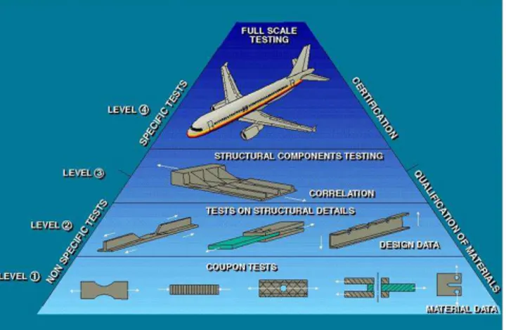
Fig. 1. (a) Pattern of a Carbon Fiber Reinforced Composite after failure under traction, (b) Kink bands under bearing (Sola et al 2016). So, for aeronautic structures more complexities were found when introducing composite structures and it was a real challenge. To secure the design and enabling the certification process a “building block” approach was retained (see Fig. 2). This approach is called “pyramid of tests”. At the first level, thousands of tests are performed to get the allowables for sizing. Tests must be at least 15 by allowable to get enough confidence in the results and to meet the aeronautic requirements (A and B Values). Moreover, for the design of bolted junctions, tests must be done for each stacking sequence and for each hole diameter. Then, step by step structural details, generic problems like debonding of stiffeners, large cuts, junctions, damage tolerance are addressed and the local designs are validated by specific tests. Then substructures are tested (for example: wing box, wing attachment, etc..) and the total structure of the plane is tested under static and fatigue loads. Doing so, for the last full carbon composite Airbus A350, about 70, 000 tests have been performed (Fualdes). Due to this complexity, a very careful approach was done by manufacturers to introduce composite materials in their product’s structure. In Fig. 3 the progressive introduction of composite is shown. Until the A350 and 787 the increase is low, from about 10 to 28 %. A careful step by step approach was chosen. Then, Boeing proposed in 2008 his 787 with about 50 % of the mass in Composite. So Airbus has to react with the A350 XWB with about the same percentage of composite. This evolution and some perspective will be developed in the following sections.
Fig. 2. Pyramid of tests
Fig. 3. Mass percentage of Composite vs year of certification for Airbus Aircrafts (courtesy of Airbus Group Innovation)
2.Significant advances from the 70s to the 90s : a careful step by step approach
Even if the Concorde (first flight 1969) had several parts made of composite, this was not really significant. A first breakthrough was the all composite helicopter rotor blades. In previous design, the blades were all metallic and their life time was only 500 hours (Airbus Helicopter Gazelle, 1970). With composite blades, their lifetime is superior to the lifetime of the helicopter itself and the owing cost decreased by 13%
(Aerospatiale). A major step was also accomplished with the Starflex rotor (Airbus Helicopter Ecureuil, 1974, see Fig. 4). It decreased the number of parts by 81 %, the weight by 48% and the cost by 55 %!
.
Fig. 4. Starflex Helicopter Rotor (Aerospatiale).
For civil aircraft, a research program was conducted in France in 1978 called “V10F”. A full carbon wing was designed and manufactured and mounted on three Dassault Falcon 10 business aircraft. They stayed in service during 25 years with no in-service accidents and a very positive experience (Robert). This first research program was used to design the first ever certified composite wing box in a civil aircraft which was the ATR72 in 1984 (Tropis et al), see Fig 5. Then, the total composite weight of the A320 (1988) was only 15%. No primary part was designed with composite materials. The next important step was the design of the keel beam of the A340-600 (1994). This is a 14 m long beam which is under the central wing box and take all the bending load of the fuselage. 250 kg were saved and it was the first primary composite part on a long range civil aircraft. The thickness was about 25 mm.
Fig. 5. Outer Wingbox ATR72. (courtesy of Airbus Group Innovation)
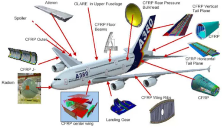
The next step was the A380 (2008), see Fig.6. Due to the size and strong mass consideration to reach a high level of performance it was mandatory to introduce even more composite in the structure and the percentage reached 25%. A challenge was to design a full composite central wing box (the most loaded substructure in an aircraft). Locally, the thickness of laminates reach 44 mm of carbon and the size of this panels is 7 mx 3m. The all CFRP horizontal tail plane has the size of a A320 wing. Most crucial parts are all CFRP made like the
vertical tail plane and the pressure bulkhead. This aircraft is also the only one to have a upper part of its fusage made of Glare (a mix of aluminum sheets and glass plies). The next step for aircraft is a all composite fuselage
Fig. 6. Composite in A380 (courtesy of Airbus Group Innovation).
3.All composite step
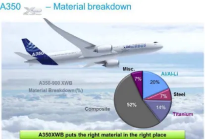
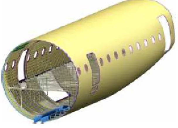
This step was initiated in military helicopter. The Tiger and the NH90 made by Airbus Helicopter have more than 90 % of their structure made of CFRP to meet military requirements, essentially the vertical speed. The start of this step was the Boeing 787 with almost all its wet surface made of carbon (see www.Boeing.com and Fig. 7) and a structure made by barrels “one shot”. The percentage of mass in composite reaches 50 %. The A350 has a four panel structure and its percentage in mass reaches 53 % (See Fig. 8). The design philosophy has evolved and it aims to put the right material at the right place (Beral 2007).
Fig. 8. Composite in A380 (courtesy of Airbus Group Innovation).
This trend has reached its maximum and now new evolutions are expected.
4.Some recent trends and perspectives
Research in aeronautic composite structures is still a growing field. If researches have mainly focused on sizing methods and damage tolerance, nowadays, advanced materials, structures and manufacturing methods are put forward. For materials, the introduction of thermoplastics is a challenge. This material has interesting capabilities in damage tolerance but its main interest is the ease of manufacturing especially with short cycles like in the automotive industry. A new kind of structures, already used by the Russians for spatial applications (Vasilliev et al, 2001, 2012), see Fig. 9 known as “geodetic structure” is studied by the aeronautic industry in Europ (www.wasis.eu). This technology is known to be very efficient (lighter than sandwich structures) but very complex and expensive. Another trend is to increase the thickness of the parts to sustain very high loads like in landing gears. Some prototype parts have reached 120 mm thick (EU program ALCAS). Finally, a strong on-going tendency is to insert out-of-plane strengths by stitching or pinning the composite (Toral et al.). The use of knitted or braided composite is also proposed. It allows designing fully 3D tailored structures. For example, the fan blade of the new Leap-X engine is based on an interlock composite (De Luycker et al, 2009). Many trials were also made to create multifunctional composite structures and are reported in Duarte et al. For example, smart structures with grids of captor, sensors or piezo actuators is a way to improve the capability of aeronautic structures by morphing the wings for example or to follow its ageing and health. It may also possible to make multifunctional parts. An example is an antenna integrated in the core of a sandwich structure which has both on the mechanical and radar functions (Smyers et al, 2008).
5.Conclusion
A short review of composite in the civil aeronautics structures was proposed. The field is extremely large and only some key-points and breakthrough were highlighted. The driven force for the research in this field are
based on human factors: diminish the weight to diminish the CO2 emission while increasing the safety. Thus,
the research on composite or lightweight structure has an wide open field in the near future for the aeronautic industry but also for all the transportation industry. The paper shows that the state-of-the-art of designing composite structure is “black metal”. So a significant research effort has to be made to provide more integrated and if possible multifunctional composite structure to increase the application field of composites.
Fig. 9. Geodetic lattice composite section (Reproduced from Vasiliev et al, 2012)
References
C. Sola, B. Castanié, L. Michel, F. Lachaud, A. Delabie and E. Mermoz. On the role of kinking in the bearing failure of composite laminates. Composite Structures. 141, 184-193. 2016
M. R. Wisnom. On the high compressive strains achieved in bending tests on unidirectional carbon-fibre/epoxy.Composites Science and Technology, Volume 43, Issue 3, 1992, Pages 229-235
S. Abrate, B. Castanié and Y. Rajapakse. Recent advances in dynamic failure of composite and sandwich structures. , Ed. Springer. 2012 Aerospatiale. Materiaux Composites : dans la grande mutation des structures. DCT 1135, Avril 1986.
V.V. Vasiliev, V.A. Barynin, A.F. Rasin. Anisogrid lattice structures – survey of development and application. Composite Structures, Volume 54, Issues 2–3, November–December 2001, Pages 361-370
V.V. Vasiliev, V.A. Barynin, A.F. Rasin . Anisogrid composite lattice structures – Development and aerospace applications. Composite Structures, Volume 94, Issue 3, February 2012, Pages 1117-1127
E. De Luycker et al. Simulation of 3D interlock composite preforming Composite Structures 88 (2009) 615–623
B. Smyers, W. Baron, J. Marshall. Structural‐Electric Characterization of a Load Bearing Antenna RF Laminate. Comptest 2008, October 14-18, Dayton (USA).
A. Tropis, M. Thomas, J.L Bounie, P. Lafon. Certification of the outer wing of the ATR 72. Journal of Aerospace Engineering, 1984, Vol 209, pp 327-339.
M. Robert. Les composites aéronautiques: 40 ans déjà et ce n'est que le début !!!Colloque Composite de TOULOUSE 2007. B. Beral. Airbus Composites Technologies & Structures. Colloque Composite de TOULOUSE 2007.
C. Fualdes. Composite@Airbus. Damage Tolerance Philosophy. FAA Workshop for Composite Damage Tolerance and Maintenance. Chicago, IL, July 19-21, 2006
J. Toral, B. Castanié, J.-J. Barrau and N. Swiergel. Multi-level analysis of low-cost Z-pinned composite joints Part 1: Single Z-pin behaviour. Composites - Part A: Applied Science and Manufacturing. 42(12)2070-2081. 2011
J. Toral, B. Castanié, J.-J. Barrau and N. Swiergel. Multi-level analysis of low-cost Z-pinned composite joints; Part 2: Joint behaviour. Composites - Part A: Applied Science and Manufacturing. 42(12)2082-2092. 2011
A. Duarte B. L. , P. Nóvoa, A. Torres Marques. Multifunctional Material Systems: A State-of-the-Art Review. Composite Structures 2016, in press.