Science Arts & Métiers (SAM)
is an open access repository that collects the work of Arts et Métiers Institute of
Technology researchers and makes it freely available over the web where possible.
This is an author-deposited version published in: https://sam.ensam.eu Handle ID: .http://hdl.handle.net/10985/13802
To cite this version :
Mario BERMUDEZ GUZMAN, Ignacio GONZALEZ PRIETO, Federico BARRERO, Hugo GUZMAN, Xavier KESTELYN, Mario Javier DURAN - An Experimental Assessment of Open-Phase Fault-Tolerant Virtual-Vector-Based Direct Torque Control in Five-Open-Phase Induction Motor Drives - IEEE Transactions on Power Electronics - Vol. 33, n°3, p.2774 - 2784 - 2018
Any correspondence concerning this service should be sent to the repository Administrator : [email protected]
An Experimental Assessment of Open-Phase
Fault-Tolerant Virtual Vector Based Direct Torque
Control in Five-Phase Induction Motor Drives
Abstract—Direct torque control (DTC) has been recently
used for the development of high performance five-phase induction motor (IM) drives, where normal operation of the system has been usually considered and the ability of DTC to manage the situation has been analyzed in comparison with different rotor field-oriented control (RFOC) strategies. The exploitation of fault-tolerant capabilities is also an interesting issue in multiphase machines, where the utility of RFOC controllers has been stated when the open-phase fault operation is considered. In this paper, the performance of DTC and RFOC controllers based on proportional resonant regulators and predictive control techniques is compared when an open-phase fault appears in a five-phase IM drive. Experimental tests are provided to compare the performance of the system using these control alternatives.
Index Terms—Direct torque control, multiphase induction
motor drives, rotor field-oriented control, open-phase fault operation.
NOMENCLATURE
DSP Digital Signal Processor.
DTC Direct torque control.
EMF Electromotive force.
IM Induction machine.
MCL Minimum copper loss.
MMF Magnetomotive force.
PCC Predictive current control.
PI Proportional integral.
PR Proportional resonant.
PWM Pulse width modulation.
RFOC Rotor field-oriented control.
THD Total harmonic distortion.
VSD Vector space decomposition.
VSI Voltage source inverter.
VV-DTC Virtual vector based DTC
ed,q Direct and quadrature feedforward terms.
In Nominal stator current value.
iα,βr Rotor currents in the α-β subspace.
ia,b,c,d,es Stator phase currents.
id,qs Direct and quadrature stator currents.
iα,βs Stator currents in the α-β subspace.
ix,ys Stator currents in the x-y subspace.
izs Stator current in the z subspace.
i*
α,βs,max Maximum reference currents in the α-β subspace.
J Cost function for PCC.
Llr Rotor leakage inductance.
Lls Stator leakage inductance.
Lm Magnetizing inductance.
Lr Rotor inductance.
Ls Stator inductance.
p Number of pole pairs.
Rr Rotor resistance.
Rs Stator resistance.
Si Switching signals of every VSI leg.
Te Electrical torque.
TL Load torque.
Tn Nominal torque.
T0 Generalized Clarke transformation
matrix.
TPOST Modified VSD transformation matrix.
Vdc DC-link voltage.
VVi Virtual voltage vectors.
va,b,c,d,es Stator phase voltages.
vd,qs Direct and quadrature stator voltages.
vα,βs Stator voltages in the α-β subspace.
vx,ys Stator voltages in the x-y subspace.
ϑ Fixed spatial displacement between
windings.
λα,βs Stator fluxes in the α-β subspace.
ωe Electrical speed.
ωm Mechanical speed.
ωr Rotor electrical speed (defined as p·ωm).
* (superscript) Reference variables. ^ (superscript) Estimated variables.
I. INTRODUCTION
ULTIPHASE drives have attracted considerable attention of the research community in recent times due to their potential benefits in electric traction and generation systems [1–3]. Compared with three-phase drives, multiphase machines present better power distribution per phase and higher overall system reliability, making them attractive when high fault-tolerant capabilities are required.
High performance control methods normally applied in conventional three-phase drives have been extended in recent times to multiphase ones to exploit their advantages [4–10]. The most common control strategy in multiphase drives is also the well-known RFOC method, used in [4] to manage a five-phase IM in normal operation with an outer PI-based speed controller and two pairs of inner PI-based stator current regulators. An alternative technique was shown in [5], where predictive current controllers substitute the conventional PI-based current regulators. This last study shows the utility of predictive current controllers in Mario Bermudez1,2, Ignacio Gonzalez-Prieto3, Federico Barrero2, Senior Member, IEEE, Hugo Guzman4, Xavier Kestelyn1,
Member, IEEE, Mario J. Duran3 1Arts et Métiers ParisTech, Lille, France ([email protected], [email protected]) 2University of Seville, Seville, Spain ([email protected])
3University of Malaga, Malaga, Spain ([email protected], [email protected]) 4University of Sheffield, Sheffield, United Kingdom ([email protected])
multiphase drives, detailing their implementation problems in modern microprocessors. An extension of [5] is shown in [6], where a detailed comparison between predictive and PI-based current controllers is provided. Other alternative controllers have been also recently extended to the multiphase drive’s case, like the DTC technique [7–9]. In these particular cases, where five and six-phases IM were considered, the focus is put on the definition of the look-up tables that were defined to reduce the stator voltage in secondary planes to minimize the generated non-torque stator current components. Last but not least, the predictive controller is extended to the regulation of the electrical torque of a five-phase machine in [10], where it is introduced like a competitor of the DTC method. However, all aforementioned controllers take into account that the multiphase machine operates under healthy conditions, not taking advantage of their ability of producing torque in faulty situations.
The use of control techniques to improve the fault-tolerance capability of the system has been also analyzed but to a lesser extent [3]. Different types of faults can occur in the drive, including short- and open-circuits faults in the power converter and electrical machine. The most common considered type of fault is the open-phase one [3], which is mainly due to damages in the power converter semiconductors or in the electrical machine, leading to the loss of an active phase. The capability of multiphase drives’ controllers to manage a fault in the system without adding extra hardware has been considered as a hot research topic. Different types of machines (permanent magnet [11,12] and induction [13–19] machines), number of phases (five [11– 16], six [17,18] or the general case of any odd number of
phases [19]) and control strategies (RFOC
[11,13,14,16,18,19] or DTC [15,16] methods) have been analyzed in recent times.
It is interesting to mention that the symmetrical five-phase induction machine with distributed windings is an important case example in the multiphase machines’ field for the research community, and several open-phase post-fault control schemes based on RFOC method have been recently reported for this type of machine [13,14,19]. These control techniques use the same outer PI-based speed control loop than in normal operation, but the inner current controllers are modified. For example, proportional resonant (PR) current controllers are proposed in [19] for the tracking of oscillating reference currents, while a model-based predictive current controller (PCC) is used in [13], where the model of the electrical drive in post-fault situation is considered. Both RFOC controllers are compared in [14], concluding that the speed control in post-fault operation is viable using either predictive or PR current control methods, leading to similar performance with the exception of the operation when unavoidable fault detection delays during a pre- to post- fault transition appear, where PCC controller is found to be more affected.
The interest of open-phase post-fault DTC schemes in five-phase IM drives has been analyzed in recent research works [15,16], where a virtual vector based DTC (VV-DTC) controller is presented. The utility of the DTC technique during the faulty condition is experimentally tested in [15], where it is shown that switching tables and applied virtual vectors must be redefined after the fault occurrence to continue the operation of the multiphase drive. Different controllers are used to manage the open-phase fault operation
of a five-phase drive in [16], comparing their performance using a simulation analysis whose conclusions must be experimentally validated. This work extends the analysis presented in [16], validating through experimentation the interest of using in five-phase IM drives VV-DTC controllers when open-phase fault conditions appear. The comparative advantages and disadvantages of applying different state-of-the-art control methods in healthy and open-phase faulty situations are also detailed, introducing a powerful tool for the controller selection for practitioners engineers interested in using multiphase drives in final applications. The paper is organized as follows. First, the behavior of the five-phase IM drive during the open-phase fault operation mode is presented in Section II. Section III details the fault-tolerant RFOC and VV-DTC schemes, including the adopted control criterion when the open-phase fault appears, that are then experimentally analyzed and compared in Section IV. Finally, the conclusions are provided in the last section. II. FIVE-PHASE IM DRIVE IN OPEN-PHASE FAULT OPERATION
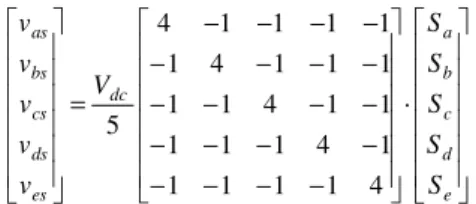
The considered five-phase drive includes a five-phase induction machine with distributed windings, equally displaced 72º, and a five-phase two-level voltage source inverter (VSI), see Fig. 1, where the switching signals of every VSI leg are represented by Si, being i = {a,b,c,d,e} and Si = 1 if the upper switch is ON and the lower switch is OFF or Si = 0 if the opposite occurs. Eq. (1) details obtained stator phase voltages from generated switching signals.
− − − − − − − − − − − − − − − − − − − − = e d c b a dc es ds cs bs as S S S S S V v v v v v · 4 1 1 1 1 1 4 1 1 1 1 1 4 1 1 1 1 1 4 1 1 1 1 1 4 5 (1)
The five-phase IM can be expressed with a set of differential equations, considering the standard assumptions of machine modeling: symmetrically distributed windings, uniform air gap, sinusoidal magnetomotive force (MMF) distribution, and negligible magnetic saturation and core losses. These equations can be simplified in the stationary reference frame using the vector space decomposition (VSD) approach [20], through the generalized Clarke transformation matrix detailed in (2). Applying this transformation matrix to the phase variable model, see eq. (3)–(4), the original five-dimensional space of the machine is transformed into two orthogonal subspaces, α-β and x-y, plus a zero sequence component, where α-β components represent the supply components of order 10n ± 1 (n = 0, 1, 2, 3, …) and are involved in the torque production. The x-y components represent supply harmonics of order 10n ± 3 (n = 0, 1, 2, 3, …), and zero sequence current components (5n, with n = 1, 2, 3, …) are cancelled because of the isolated neutral point. The utilized system can be modeled as follows:
[ ]
= 2 / 1 2 / 1 2 / 1 2 / 1 2 / 1 3 sin sin 4 sin 2 sin 0 3 cos cos 4 cos 2 cos 1 4 sin 3 sin 2 sin sin 0 4 cos 3 cos 2 cos cos 1 5 2 0 ϑ ϑ ϑ ϑ ϑ ϑ ϑ ϑ ϑ ϑ ϑ ϑ ϑ ϑ ϑ ϑ T (2)[
]
[ ] [
]
T es ds cs bs as T zs ys xs s s i i i i T i i i i i iα β = 0 ⋅ (3)[
]
[ ] [
]
T es ds cs bs as T zs ys xs s s v v v v T v v v v v vα β = 0 ⋅ (4) r m s s s s i dt d L i dt d L R vα ⋅α + ⋅ α ⋅ + = (5) r m s s s s i dt d L i dt d L R vβ ⋅ β + ⋅ β ⋅ + = (6) xs ls s xs i dt d L R v ⋅ ⋅ + = (7) ys ls s ys i dt d L R v ⋅ ⋅ + = (8)(
r r m s)
r s m r r r i L i L i dt d L i dt d L R ⋅ α + ⋅ α +ω ⋅ ⋅ β + ⋅ β ⋅ + = 0 (9)(
r r m s)
r s m r r r i L i L i dt d L i dt d L R ⋅ β + ⋅ β −ω ⋅ ⋅ α + ⋅ α ⋅ + = 0 (10)where Ls = Lls + Lm, Lr = Llr + Lm and ωr = p·ωm, being p the pole pairs number and ωm the mechanical speed. Subscripts s and r indicate stator and rotor variables, while subscripts l and m denote leakage and magnetizing inductance, respectively.
When an open-phase fault occurs, the behavior of the system varies. The current in the faulty phase is zero, its voltage is given by the back electromotive force (back-EMF) and the model of the system changes. A modified VSD transformation matrix (TPOST) is considered in [13], where phase ‘a’ is assumed to be the faulty phase, to cope with the asymmetrical stator/rotor impedance terms that are obtained if T0 is considered. Consequently, the five-phase IM is modeled using stationary reference frames with (5)–(10), but a degree of freedom is lost. For example, if phase ‘a’ is the faulty phase, the x-current component is inherently fixed to the α-current component (ixs = –iαs), and only y-current component is controllable in the x-y subspace. In this way, equations (1)–(4) are substituted by:
+ − − − − − − − − − − − − − = 1 1 1 1 4 · 3 1 1 1 1 3 1 1 1 1 3 1 1 1 1 3 4 dt di dt di L S S S S V v v v v s r m e d c b dc es ds cs bs α α (11)
[
]
− − − − = 1 1 1 1 8 sin 6 sin 4 sin 2 sin 4 sin 3 sin 2 sin sin 1 4 cos 1 3 cos 1 2 cos 1 cos 5 2 ϑ ϑ ϑ ϑ ϑ ϑ ϑ ϑ ϑ ϑ ϑ ϑ POST T (12)[
]
[
] [
]
T es ds cs bs POST T zs ys s s i i i T i i i i iα β = · (13)[
]
[
] [
]
T es ds cs bs POST T zs ys s s v v v T v v v v vα β = · (14)where the second right hand side term in (11) corresponds to the back-EMF of the faulty phase. The implementation of control schemes when the open-phase situation appears is detailed in the next section.
III. RFOC AND VIRTUAL VECTOR BASED DTC IN OPEN-PHASE FAULT OPERATION
After the open-phase fault occurs, the remaining degree of freedom (the y-current component if the faulty phase is ‘a’, as stated before) needs to be established according to a certain strategy. Different criteria have been recently adopted in the literature in relation with ensuring post-fault operation and minimum copper losses, minimum derating (i.e. maximum load torque) or minimum torque ripple [11,19,21]. The minimum copper loss (MCL) criterion is adopted in this case to obtain a fair comparison between RFOC and VV-DTC.
When MCL is used with RFOC techniques, the y-current reference, which does not contribute to the torque production, is set to zero (iys* = 0). The obtained losses are then minimized and the efficiency of the system is improved. Notice that the MCL method, as it is stated in [21], leads to unequal peaks in the phase currents and does not achieve the maximum post-fault available torque. The maximum reference currents in the α-β subspace in MCL to
impose a rotating circle-shaped MMF are i*
αs,max = 0.6813·In·sin(ωt) and i*βs,max = –0.6813·In·cos(ωt), being In the nominal stator current value [21].
On the other hand, the VV-DTC method is implemented using a look-up table [8,22] and applying a MCL-type criterion. Zero average volts-per-second in the y direction is then produced in post-fault operation using voltage vectors, which will also force close to zero current in the y direction in distributed-winding symmetrical five-phase induction machine.
A. RFOC technique
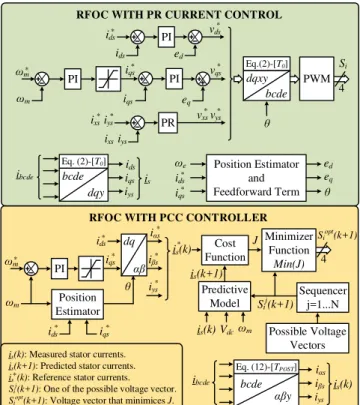
Fig. 2 shows the scheme of RFOC controllers considered in this case [13,19]. The control is implemented in a synchronous (d-q) reference frame, being the q-current reference obtained using the speed error and a PI-based controller, whereas the d-current reference is a constant value that provides the rated flux in steady-state operation. The inner fault-tolerant current controllers are implemented considering PR regulators (RFOC-PR from now on) and finite-control set model-based PCC techniques (RFOC-PCC in what follows). Notice that the MCL criterion is imposed in this analysis (ixs* = –iαs, iys* = 0).
When a conventional RFOC method is used to manage the open-phase fault operation, PI controllers in secondary planes (x-y in this case) are substituted by PR regulators to cope with the oscillating nature of the references (ixs* = –iαs and iys* = 0 as a consequence of the post-fault control criterion). This method (RFOC-PR) is proposed in [19], where PR regulators are implemented adding the outputs of two independent PI controllers to track positive and negative sequences of the x-y stator current references, obtaining the voltage references (vxs* and vys*). Inner current controllers in relation with the d-q plane are PI-based, including two feedforward terms (ed and eq shown in Fig. 2) to improve the controller performance. Then, the obtained d-q voltage references are first converted into the stationary frame (α-β plane) by means of the inverse Park matrix, grouped with the obtained x-y voltage references into α-β-x-y voltage references and transformed into reference phase voltages using T0, detailed in eq. (2), to obtain a switching PWM pattern for the multiphase VSI.
The RFOC-PCC control scheme detailed in [13] includes an inner predictive current stator controller as the main
difference with RFOC-PR technique. This predictive controller is based on the discretization of the post-fault five-phase IM drive model (predictive model in Fig. 2). Using this predictive model, the future stator current values, is(k+1), can be obtained in faulty operation with the measured stator currents, is(k), mechanical speed, ωm, and DC-link voltage, Vdc. The control objective of the predictive controller lies on defining a cost function J and finding the switching state to be applied, Siopt(k+1), that minimizes this cost function (see Fig. 2). This optimum value Siopt(k+1) is obtained computing the predictive model for every available switching state Sij (k+1) to obtain the future stator current and find the one which minimizes J. The cost function considered in this work is based on the difference between the reference and the predicted stator currents and it is shown in eq. (15). Note that the reference stator currents are converted from the synchronous d-q frame to the stationary α-β using the Park transformation and the MCL criterion is again applied (ixs* = –iαs, iys* = 0), while the measured stator phase currents (ibcde) are transformed into α-β-y coordinates using the TPOST matrix, see eq. (12).
) 1 ( ) 1 ( ) 1 ( ) 1 ( ) 1 ( ) 1 ( * * * + − + + + − + + + − + = k i k i k i k i k i k i J ys ys s s s s α β β α (15) B. VV-DTC method
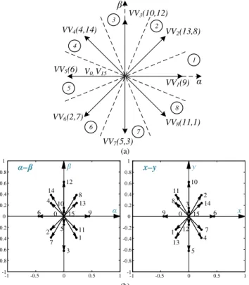
The extension of VV-DTC technique to the open-phase fault operation has been recently presented in [15], where the scheme summarized in Fig. 3 is proposed. It is based on an outer PI closed-loop speed control, while two-level stator flux and three-level electromechanical torque hysteresis comparators are used to provide the control action (applied stator voltage vector) through a predefined look-up table. For this purpose, eight virtual voltage vectors (VVi) are defined in the α-β subspace, each one placed in the center of a different sector, as it is shown in Fig. 4(a). These virtual vectors are obtained as follows:
(
1, 2)
1 v1 2 v2iv v vK v K
VV = + (16)
where:
• v1 and v2 are two available voltage vectors in post-fault situation, see Fig. 4(b), obtained from the phase voltages of eq. (11) and the modified VSD transformation matrix (TPOST) of eq. (12).
• Kv1 and Kv2 are dwell time ratios that are calculated to get zero average volts-per-second in the y direction, following the MCL-type criterion (see [15]).
The applied virtual voltage vector is selected from the look-up table shown in Table I, depending on the stator flux position in the α-β plane (8 different sectors are defined) and the error signals dλs and dTe, discretized using two hysteresis regulators. Notice that the stator flux is obtained using the observer detailed in [10] and the torque is estimated as:
) · ˆ · ˆ ·( · 2 5 ˆ s s s s e p i i T = λα β −λβ α (17)
It is important to highlight that the phase ‘a’ is considered as the faulty phase in this work. In the case that the fault occurs in a phase different from phase ‘a’, there are two valid
Minimizer Function
Min(J)
ωm PI
RFOC WITH PCC CONTROLLER
ωm* ids ids* * iqs iβs* Cost Function * iαs 4 Position Estimator * iys * iqs * ids dq αβ is(k) * θ Siopt(k+1) J Possible Voltage Vectors Predictive Model Sequencer j=1...N is(k+1) Sij(k+1) ibcde iαs iβs iys is(k) ωm Vdc is(k)
is(k): Measured stator currents. is(k+1): Predicted stator currents. is (k): Reference stator currents. Sij(k+1): One of the possible voltage vector. Siopt(k+1): Voltage vector that minimices J.
* αβy bcde Eq. (12)-[TPOST] PWM ωm PI
RFOC WITH PR CURRENT CONTROL
Position Estimator and Feedforward Term ωm* ids ids* PI PI iqs eq * iqs vqs* ed * vds 4 PR * vys * vxs * iys * ixs iys ixs Si ed eq θ * ids ωe * iqs ibcde ids iqs iys is θ bcde dqxy Eq.(2)-[T0] Eq. (2)-[T0] bcde dqy
Fig. 2. RFOC scheme based on proportional resonant (upper plot) and predictive (bottom plot) current controllers.
5-phase 2-level Inverter ωm ibs ics ids ies Vdc ωm PI dTe dλs Look-up Table (Table I) λ^s T^e 5-PHASE IM ias=0 VV-DTC Flux estimator (see [10]) Flux position iαs ixs iβs iys λs ^ Sector identification ωm* * λs * Te Torque estimator +1 -1 0 iαs iβs +1 -1 Eq. (17) αβy bcde Eq. (12)-[TPOST]
Fig. 3. VV-DTC scheme regulating five-phase IM drives in open-phase fault situation [15]. The ‘^’ and ‘*’ symbols identify the estimated and reference variables, respectively.
solutions that can be used. The first one requires recalculating the transformation matrix and obtaining new voltage vectors in post-fault situation, virtual vectors with their respective dwell times and the look-up table. Then, it is
necessary to keep all these parameters in the
microprocessor’s (DSP) memory. When the fault happens, the controller must select the correct matrix, virtual vectors and look-up table, and use them to control the multiphase drive. This is a viable implementation alternative as long as the DSP’s memory is more than sufficient for the control method. The second solution would need to readjust the order of the machine phases in order to establish the faulty power leg as phase ‘a’. This is also possible thanks to the symmetry of the multiphase drive and allows to use the
same transformation matrix TPOST, see eq. (12),
independently of the faulty phase. This second approach would also use the same virtual vectors and look-up table
defined for phase ‘a’ but shows an important
implementation drawback in comparison with the previous one: the GPIO modules that are used in the DSP to control the power converter (switching signals) need to be readjusted. In addition, the computational cost is slightly higher than in the first case, and what it is worst, a transition
0 15 1 2 3 4 5 6 7 8 9 10 11 12 13 14 β α– -1 -0.5 0 0.5 1 -1 -0.8 -0.6 -0.4 -0.2 0 0.2 0.4 0.6 0.8 1 β α 0 15 4 1 5 8 12 9 13 2 6 3 7 10 14 11 -1 -0.5 0 0.5 1 -1 -0.8 -0.6 -0.4 -0.2 0 0.2 0.4 0.6 0.8 1 y x x–y VV1(9) VV2(13,8) VV8(11,1) VV7(5,3) VV4(4,14) V0, V15 VV5(6) VV6(2,7) VV3(10,12) α β 2 3 4 5 6 7 8 1 (a) (b)
Fig. 4. Open-phase fault operation of five-phase IM drives. (a) Virtual voltage vectors (VVi) in the α-β subspace. (b) Available voltage vectors in
the α-β (left plot) and x-y (right plot) planes. TABLEI
LOOK-UP TABLE FOR THE VV-DTC CONTROLLER IN POST-FAULT SITUATION PROPOSED IN [15]
dλs dTe
Position of stator flux (Sector)
1 2 3 4 5 6 7 8 +1 +1 VV2 VV3 VV4 VV5 VV6 VV7 VV8 VV1 -1 VV8 VV1 VV2 VV3 VV4 VV5 VV6 VV7 0 V0 V15 V0 V15 V0 V15 V0 V15 -1 +1 VV4 VV5 VV6 VV7 VV8 VV1 VV2 VV3 -1 VV6 VV7 VV8 VV1 VV2 VV3 VV4 VV5 0 V15 V0 V15 V0 V15 V0 V15 V0
in the control action is introduced if the GPIO modules are reassigned, worsening the performance of the controlled system when managing the faulty situation.
IV. EXPERIMENTAL RESULTS
The RFOC and VV-DTC methods have been implemented in a lab-scale multiphase system to compare the obtained results. The experimental test rig is shown in Fig. 5. Its main component is a five-phase IM with 30-slots and three pairs of poles, whose electrical parameters have been determined using different tests [23,24] that provide the specifications summarized in Table II. The multiphase electrical machine is driven by two conventional three-phase VSIs from Semikron (SKS22F modules), connected to an external DC power supply that provides a DC-link voltage of 300 V. The control
actions are obtained using Texas Instruments
TMS320F28335 DSP placed on a MSK28335 board. The
rotor speed is obtained with a digital encoder
(GHM510296R/2500) and one peripheral of the DSP (the enhanced quadrature encoder pulse or eQEP). A programmable load torque is set by an independently controlled DC machine, which is mechanically coupled to the five-phase IM during the experiments. Finally, the fault occurrence is emulated opening a power relay connected in series with the faulty phase (phase ‘a’).
Current Sensors DC MOTOR 5-PHASE IM a b DC MOTOR DRIVE RS232 Serial Ports 5-PHASE IM DRIVE Switching Signals Phase Currents CONTROL BOARD POWER ELECTRONIC CONVERTERS (VSIs) Speed Encoder (ωm) DC-LINK Vdc a b c d e
Fig. 5. Experimental test rig. The five-phase IM (bottom right side) is controlled using two three-phase VSI and an electronic control board based on the MSK28335 (center middle). An independently controlled DC motor (bottom left side) provides a programmable load torque, while the DC-link voltage is set using an external DC supply (upper side).
TABLEII
ELECTRICAL PARAMETERS OF THE FIVE-PHASE IM
Parameter Value Parameter Value
Rs (Ω) 12.85 M (mH) 681.70
Rr (Ω) 4.80 p 3
Lls (mH) 79.93 Tn (N·m) 6.50
Llr (mH) 79.93 λsn (Wb) 0.435
TABLEIII
PROPORTIONAL AND INTEGRAL PARAMETERS OF PI AND PR CONTROLLERS
RFOC-PR RFOC-PCC VV-DTC Controller Kp Ki Kp Ki Kp Ki PI speed 0.15 6 0.08 6 0.25 5 PI d-current 336 18 - - - - PI q-current 80 390 - - - - PR x-current 12.5 322 - - - - PR y-current 12.5 322 - - - -
The experiments are performed with a constant stator current reference in the d-axis of 0.57 A for RFOC methods, with an equivalent stator flux reference of 0.435 Wb in the VV-DTC scheme. The hysteresis bands of the VV-DTC torque and flux regulators are programmed at 0.77% and 1.15% of the rated values, respectively. The proportional and integral constants of the PI and PR controllers used in this study are shown in Table III and were adjusted using a trial and error procedure. The configured control sampling time is 0.1 ms in RFOC-PCC and VV-DTC methods, and 0.4 ms in RFOC-PR, giving a similar switching frequency of about 2.5 kHz in all cases. Figs. 6 to 11 summarize the obtained results that include the performance of the system in steady and transient-states, and show the performance from pre- to post-fault situations. The first, second and third columns in each figure show the obtained results using the RFOC-PR, the RFOC-PCC and the VV-DTC control methods, respectively.
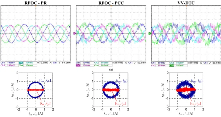
The steady-state performance in faulty operation is firstly examined, driving the motor at 500 rpm when different load torques are demanded. Fig. 6 shows the evolution of the stator currents using RFOC and VV-DTC controllers when the applied load torque is 0.28·Tn (about half of the maximum achievable post-fault torque when the MCL
criterion is used [13]). Regardless of the control strategy, stator currents in ‘b’ and ‘e’ phases are equal in magnitude and possess unequal peak values compared to ‘c’ and ‘d’ stator phase currents, Fig. 6(a), being the obtained result in accordance with the applied MCL criterion [21]. Since the MMF remains the same in healthy and faulty operations, a circular trajectory is obtained in the α-β currents, see blue circles in Fig. 6(b). However, a horizontal line is observed in the x-y plane because ixs = –iαs and iys is nearly null, see red line in Fig. 6(b). The main difference between the three controllers is that the harmonic content (amplitude of the current ripple in the circular plot) is higher using VV-DTC in the α-β and x-y plane, while the use of PR current controllers with RFOC techniques offers the best performance in steady state.
If the maximum post-fault torque in steady state with the MCL criterion is applied (0.56·Tn) [13], the obtained results are summarized in Fig. 7. Similar conclusions are achieved when RFOC methods are analyzed, see stator phase currents and circular plots of stator currents in α-β and x-y planes in Fig. 7(a) and Fig. 7(b), respectively. Notice also that the reference speed is controlled during the experiment, Fig. 7(c). The situation changes when the VV-DTC method is used (right plots in Fig. 7): the speed is not regulated, α-β currents do not describe a circular trajectory and peak values of stator phase currents are different. This is a consequence of using virtual voltage vectors of lower amplitude than the available voltage vectors, which reduces the harmonic content of VV-DTC at the expense of reducing also the DC-link voltage utilization. It can be then concluded that the maximum load torque that the VV-DTC method can manage in post-fault operation is lower than using RFOC techniques.
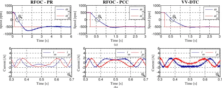
The compared dynamic performance in faulty operation using the different control schemes is then analyzed. A reversal speed test is done, where the reference speed is changed from 500 to –500 rpm at t = 0.2 s, while no electrical load torque is demanded to the multiphase drive using the controlled DC machine. Fig. 8 shows the obtained results, presenting the VV-DTC technique lower settling times and overshoots than RFOC methods, Fig. 8(a). The harmonic content in the stator currents is lower using RFOC techniques, as it is illustrated in the zoom-in of the α-β stator currents at the zero-speed-crossing instant, Fig. 8(b).
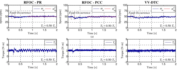
Next, the transition from pre- to post-fault operation is studied in Fig. 9, showing the performance of the controlled system. Note that a delay of 40 ms between the fault occurrence and the control action is considered to take into account the fault detection process. The motor is driven at 500 rpm, before and after the fault occurrence, with a constant load torque of 0.50·Tn. It is interesting to note the degradation of the speed tracking when the RFOC-PCC method is used, see Fig. 9(a), where the mechanical speed of the system drops to about 480 rpm. The control action is also poor when the RFOC-PR method is used, see Fig. 9(b), where the harmonic content in the generated electrical torque is the highest among the considered control methods. In this case, an oscillating ripple at double the fundamental frequency appears due to the q-current oscillation because of a negative sequence current that cannot be regulated by the outer PI-based speed and flux d-q controllers [14, 19]. This is not the case when the VV-DTC technique is used, being a more robust control method in the experiment. Once the post-fault controllers are activated at 0.24 s, the control
action is recovered and the speed is regulated in all cases. In particular, VV-DTC method shows a higher settling time.
Focusing on the VV-DTC technique, the obtained healthy stator phase currents in the transient operation between healthy and faulty situation are shown in Fig. 10. The speed reference is fixed at 500 rpm, while the demanded load torque is programmed about 28%, Fig. 10(a), and 50%, Fig. 10(b), of the nominal one. It is observed that the healthy phase currents increase their magnitude to compensate the faulty phase, being equal the stator current in ‘b’ and ‘e’ phases and in ‘c’ and ‘d’, but unequal among them in accordance with the MCL criterion.
The low speed operation of the drive is finally analyzed in Fig. 11. A delay of 40 ms between the fault occurrence and the control action is again considered. A constant load of 0.50·Tn is applied, and a reference speed of 50 rpm is set. Similar responses are obtained using different controllers, although the VV-DTC method takes longer to settle down to its steady-state speed, Fig. 11(a). The RFOC-PR method offers an oscillating ripple at double the fundamental frequency, like in the previous test, Fig. 11(b).
A qualitative comparative analysis between the studied control schemes is summarized in Table IV, and the obtained assumptions can be detailed as follows:
• Different fault detection delays (from 20 to 100 ms) have been tested in the analyzed transitions from pre- to post-fault situation, concluding that the VV-DTC method maintains the control action during the transition and shows the highest robustness in the study.
• A change in the model of the physical system is imperative when RFOC-PCC and VV-DTC methods are used, while the RFOC-PR technique does not require this change.
• The controller must be redefined if RFOC-PR and
VV-DTC techniques are used (substitution of conventional PI controllers and definition of a new look-up table, respectively) when the fault appears. In contrast, a change in the cost function is only needed after the fault detection when RFOC-PCC is used.
• The computational cost of the implemented algorithms shows the lowest value for the VV-DTC method and the largest one for the RFOC-PCC technique.
• The quality of the obtained stator current in terms of THD depicts the lowest values for the RFOC-PR method, while the VV-DTC technique produces the highest current ripple.
• The maximum obtained torque in faulty situation is higher (roughly about 10 %) with RFOC methods. All in one it can be concluded that there is no ideal controller to manage the open-phase fault appearance. If robustness, simplicity or computational cost are the desirable characteristics, the VV-DTC method offers the best performance. However, if the quality of the obtained stator current or the maximum post-fault electrical torque are demanded in post-fault operation, the RFOC techniques are superior.
(a) (b) -2 -1 0 1 2 -2 -1 0 1 2 iαs,ixs[A] 0 1 2 -1 -2 iβs [A ] iys , , s iα βs] [ i , iys] s ix [ -2 -1 0 1 2 -2 -1 0 1 2 iαs,ixs[A] 0 1 2 -1 -2 iβs [A ] iys , , s iα βs] [ i , iys] s ix [ixs, iys] [ -2 -1 0 1 2 -2 -1 0 1 2 iαs,ixs[A] 0 1 2 -1 -2 iβs [A ] iys , , s iα βs] [ i , iys] s ix [ RFOC - PR RFOC - PCC VV-DTC
Fig. 6. Steady-state faulty operation when the reference speed is set to 500 rpm, a load torque of 28% of the nominal one is demanded, and RFOC-PR (left plots), RFOC-PCC (middle plots) and VV-DTC (right plots) controllers are used. (a) Stator phase currents obtained with the scope (± 1% of precision in the current probes). (b) Stator phase currents in α-β and x-y planes.
0 0.2 0.4 0.6 0.8 1 ωm ω*m Time [s] 0 0.2 0.4 0.6 0.8 1 400 450 500 550 600 S p ee d [ rp m ] ωm ω * m (b) (c) 0 0.2 0.4 0.6 0.8 1 ωm ω * m 400 450 500 550 600 S p ee d [ rp m ] Time [s] 0 0.2 0.4 0.6 0.8 1 ω m ω * m 0 0.2 0.4 0.6 0.8 1 ωm ω * m 400 450 500 550 600 S p ee d [ rp m ] Time [s] 0 0.2 0.4 0.6 0.8 1 ω m ω * m -2 -1 0 1 2 iαs,ixs[A] 0 1 2 -1 -2 iβs [A ] iys , iα [ s,iβs] ys] ixs [ , i -2 -1 0 1 2 iαs,ixs[A] 0 1 2 -1 -2 iβs [A ] iys , iαs [ ,iβs] ys] ixs [ ,i -2 -1 0 1 2 iαs,ixs[A] 0 1 2 -1 -2 iβs [A ] iys , iα [ s,iβs] ys] ixs [ ,i RFOC - PR RFOC - PCC VV-DTC (a)
Fig. 7. Steady-state faulty operation when the reference speed is set to 500 rpm, a load torque of 56% of the nominal one is demanded, and RFOC-PR (left plots), RFOC-PCC (middle plots) and VV-DTC (right plots) controllers are used. (a) Stator phase currents obtained with the scope (± 1% of precision in the current probes). (b) Stator phase currents in α-β and x-y planes. (c) Speed response (‘*’ symbol identifies the reference speed).
(a) (a) 0 0.5 1 1.5 2 2.5 3 ωm ω* m ω m ω* m -1000 -500 0 500 1000 S p ee d [ rp m ] Time [s] 0 0.5 1 1.5 2 2.5 3 (b) (b) iαs iβs Time [s] 0.3 0.4 0.5 0.6 0.7 -6 -4 0 4 6 C u rr en t [A ] 2 -2 iα s iβs 0 1 2 3 4 5 6 ωm ω* m -1000 -500 0 500 1000 S p ee d [ rp m ] Time [s] 0 1 2 3 4 5 6 ω m ω* m (b) 0.3 0.4 0.5 0.6 0.7 iαs iβs Time [s] 0.3 0.4 0.5 0.6 0.7 -6 -4 0 4 6 C u rr en t [A ] 2 -2 iα s iβs ωm ω* m Time [s] 0 0.5 1 1.5 2 2.5 3 ω m ω* m -1000 -500 0 500 1000 S p ee d [ rp m ] 0.3 0.4 0.5 0.6 0.7 iαs iβs iα s iβs Time [s] 0.3 0.4 0.5 0.6 0.7 -6 -4 0 4 6 C u rr en t [A ] 2 -2 RFOC - PR RFOC - PCC VV-DTC
Fig. 8. Dynamic performance of the system in faulty operation when RFOC-PR (left plots), RFOC-PCC (middle plots) and VV-DTC (right plots) controllers are used. The reference speed is changed from 500 to –500 rpm at t = 0.2 s, while no electrical load torque is demanded. (a) Speed response. (b) Stator current waveforms in the α-β plane at the zero speed crossing point.
VV-DTC (a) (b) RFOC - PR 0 0.2 0.4 0.6 0.8 TTe e -3 0 3 6 9 T o rq u e [ N ·m ] Time [s] 0 0.2 0.4 0.6 0.8 TL = 0.50·Tn RFOC - PCC 0 0.5 1 1.5 2 ωm ω * m 400 450 500 550 600 S p ee d [ rp m ] TL = 0.50·Tn Time [s] 0 0.5 1 1.5 2 ω m ω * m Fault Occurrence ωm ω * m 400 450 500 550 600 S p ee d [ rp m ] Time [s] 0 0.5 1 1.5 2 TL = 0.50·Tn ωm ω* m Fault Occurrence 0 0.5 1 1.5 2 ωm ω*m 400 450 500 550 600 S p ee d [ rp m ] Time [s] 0 0.5 1 1.5 2 Fault Occurrence TL = 0.50·Tn ωm ω* m TTe e -3 0 3 6 9 T o rq u e [ N ·m ] Time [s] 0 0.2 0.4 0.6 0.8 TL = 0.50·Tn -3 0 3 6 9 T o rq u e [ N ·m ] Time [s] 0 0.2 0.4 0.6 0.8 0 0.2 0.4 0.6 0.8 Te Te TL = 0.50·Tn
Fig. 9. Pre- to post-fault transition under realistic conditions (a delay of 40 ms in the fault detection is assumed). RFOC-PR (left plots), RFOC-PCC (middle plots) and VV-DTC (right plots) techniques are considered. A load torque of about 50% of the nominal one and a reference speed of 500 rpm are considered. (a) Speed response. (b) Zoom-in of the generated electrical torque at the fault occurrence instant.
(a) (b) Pre-Fault Post-Fault ibs ies ics ids ibs ics ids ies Pre-Fault Post-Fault
Fig. 10. Healthy stator phase currents in the transient operation between healthy and faulty situation when the VV-DTC method is applied. The speed reference is considered to be 500 rpm, while the demanded load torque is set up at about (a) 28% and (b) 50% of the nominal one.
VV-DTC (a) (b) RFOC - PR RFOC - PCC 0 0.2 0.4 0.6 0.8 Te -3 0 3 6 9 T o rq u e [ N ·m ] Te TL = 0.50·Tn Time [s] 0 0.5 1 1.5 2 TTe e -3 0 3 6 9 T o rq u e [ N ·m ] TL = 0.50·Tn Time [s] 0 0.5 1 1.5 2 0 0.5 1 1.5 2 Te Te -3 0 3 6 9 T o rq u e [ N· m ] TL = 0.50·Tn Time [s] 0 0.5 1 1.5 2 0 0.5 1 1.5 2 ωm ω * m Time [s] 0 0.5 1 1.5 2 Fault Occurrence TL = 0.50·Tn ω m ω * m 0 25 50 75 100 S p ee d [ rp m ] ωm ω * m TL = 0.50·Tn Time [s] 0 0.5 1 1.5 2 ω m ω * m Fault Occurrence 0 25 50 75 100 S p ee d [ rp m ] ωm ω * m Time [s] 0 0.5 1 1.5 2 TL = 0.50·Tn ω m ω * m Fault Occurrence 0 25 50 75 100 S p ee d [ rp m ]
Fig. 11. Pre- to post-fault transition at low speed operation, where a 40 ms delay in the fault detection process is assumed. PR (left plots), RFOC-PCC (middle plots) and VV-DTC (right plots) techniques are considered. A load torque of about 50% of the nominal one and a reference speed of 50 rpm are considered. (a) Speed response. (b) Generated electrical torque.
TABLEIV
QUALITATIVE COMPARISON BETWEEN RFOC AND VV-DTC METHODS IN OPEN-PHASE FAULT OPERATION
Close-loop system performance RFOC−PR RFOC−PCC VV−DTC
Speed tracking error when the fault appears Negligible High Slight
Torque tracking loss in control during the delay Yes Yes No
Robustness against fault detection delay ↓ ↓↓ ↑↑
Change in the Clarke transformation matrix No Yes Yes
Reconfiguration of the controller Yes No Yes
Computational cost ↑ ↑↑ ↓
Stator current THD ↓ ↑ ↑↑
Maximum available torque 56% of Tn 56% of Tn 50% of Tn
V. CONCLUSION
The use of the DTC technique is not habitual in the multiphase drives’ field, opposite to the three-phase case, due to the intrinsic limitations of the method that is only applied to regulate the flux and torque of the drive. However, some attempts of using the DTC technique with the lowest number of phases in the multiphase drive have been recently done, where normal/healthy operating conditions and the five-phase IM were considered. Open-five-phase fault operation of the five-phase IM has been also newly analyzed, and the obtained performances are experimentally validated in this work, where a detailed comparative analysis between VV-DTC and RFOC controllers is presented. Obtained results show that the VV-DTC method has the capacity of managing lower maximum electrical torques than RFOC techniques. Higher harmonic content is also obtained in the stator phase current when the VV-DTC technique is applied, as it occurs in the three-phase case. However, if DTC is used in normal operation due to its well-known advantages (fast torque response and low parameter sensitivity, to name a few), the use of a post-fault VV-DTC is a viable option that proves to increase the robustness against fault detection delays while simplicity and low computational cost are preserved. This results in an interesting alternative to RFOC methods in industry applications where the fault-tolerant capability of the drive needs to be increased.
REFERENCES
[1] E. Levi, “Advances in Converter Control and Innovative Exploitation of Additional Degrees of Freedom for Multiphase Machines,” IEEE
Trans. Ind. Electron., vol. 63, no. 1, pp. 433-448, Jan. 2016.
[2] F. Barrero and M.J. Duran, “Recent Advances in the Design, Modeling and Control of Multiphase Machines – Part 1,” IEEE Trans.
Ind. Electron., vol. 63, no. 1, pp. 449-458, Jan. 2016.
[3] M.J. Duran and F. Barrero, “Recent Advances in the Design, Modeling and Control of Multiphase Machines – Part 2,” IEEE Trans.
Ind. Electron., vol. 63, no. 1, pp. 459-468, Jan. 2016.
[4] M. Jones, S.N. Vukosavic, D. Dujic and E. Levi, “A Synchronous Current Control Scheme for Multiphase Induction Motor Drives,”
IEEE Trans. Energy Convers., vol. 24, no. 4, pp. 860-868, Dec. 2009.
[5] F. Barrero, M.R. Arahal, R. Gregor, S. Toral and M.J. Duran, “A Proof of Concept Study of Predictive Current Control for VSI-Driven Asymmetrical Dual Three-Phase AC Machines,” IEEE Trans. Ind.
Electron., vol. 56, no. 6, pp. 1937-1954, Jun. 2009.
[6] C.S. Lim, E. Levi, M. Jones, N.A. Rahim and W.P. Hew, “FCS-MPC-Based Current Control of a Five-Phase Induction Motor and its Comparison with PI-PWM Control,” IEEE Trans. Ind. Electron., vol. 61, no. 1, pp. 149-163, Jan. 2014.
[7] L. Parsa and H.A. Toliyat, “Sensorless Direct Torque Control of Five-Phase Interior Permanent-Magnet Motor Drives,” IEEE Trans. Ind.
Appl., vol. 43, no. 4, pp. 952-959, Jul./Aug. 2007.
[8] L. Zheng, J.E. Fletcher, B.W. Williams and X. He, “A Novel Direct Torque Control Scheme for a Sensorless Five-Phase Induction Motor Drive,” IEEE Trans. Ind. Electron., vol. 58, no. 2, pp. 503-513, Feb. 2011.
[9] K.D. Hoang, Y. Ren, Z.Q. Zhu and M. Foster, “Modified switching-table strategy for reduction of current harmonics in direct torque controlled dual-three-phase permanent magnet synchronous machine drives,” IET Electric Power Appl., vol. 9, no. 1, pp. 10-19, Jan. 2015. [10] J.A. Riveros, F. Barrero, E. Levi, M. Duran, S. Toral and M. Jones,
“Variable-Speed Five-Phase Induction Motor Drive Based on Predictive Torque Control,” IEEE Trans. Ind. Electron., vol. 60, no. 8, pp. 2957-2968, Aug. 2013.
[11] H.M. Ryu, J.W. Kim and S.K. Sul, “Synchronous-Frame Current Control of Multiphase Synchronous Motor Under Asymmetric Fault Condition Due to Open Phases,” IEEE Trans. Ind. Appl., vol. 42, no. 4, pp. 1062-1070, Jul./Aug. 2006.
[12] S. Dwari and L. Parsa, “Fault-Tolerant Control of Five-Phase Permanent-Magnet Motors With Trapezoidal Back EMF,” IEEE
Trans. Ind. Electron., vol. 58, no. 2, pp. 476-485, Feb. 2011.
[13] H. Guzman, M.J. Duran, F. Barrero, B. Bogado and S. Toral, “Speed Control of Five-Phase Induction Motors With Integrated Open-Phase Fault Operation Using Model-Based Predictive Current Control Techniques,” IEEE Trans. Ind. Electron., vol. 61, no. 9, pp. 4474-4484, Sep. 2014.
[14] H. Guzman, M.J. Duran, F. Barrero, L. Zarri, B. Bogado, I. Gonzalez-Prieto and M.R. Arahal, “Comparative Study of Predictive and Resonant Controllers in Fault-Tolerant Five-phase Induction Motor Drives,” IEEE Trans. Ind. Electron., vol. 63, no. 1, pp. 606-617, Jan. 2016.
[15] M. Bermudez, I. Gonzalez-Prieto, F. Barrero, H. Guzman, M.J. Duran and X. Kestelyn, “Open-Phase Fault-Tolerant Direct Torque Control Technique for Five-Phase Induction Motor Drives,” IEEE Trans. Ind.
Electron., vol. 64, no. 2, pp. 902-911, Feb. 2017.
[16] M. Bermudez, H. Guzman, I. Gonzalez-Prieto, F. Barrero, M.J. Duran and X. Kestelyn, “Comparative Study of DTC and RFOC Methods for the Open-Phase Fault Operation of a 5-Phase Induction Motor Drive,” in Proc. 41st Annu. Conf. IEEE Ind. Electron. Soc., Yokohama, Japan, Nov. 9-12, 2015, pp. 2702-2707.
[17] L. Alberti and N. Bianchi, “Experimental Tests of Dual Three-Phase Induction Motor Under Faulty Operating Condition,” IEEE Trans.
Ind. Electron., vol. 59, no. 5, pp. 2041-2048, May 2012.
[18] H.S. Che, M.J. Duran, E. Levi, M. Jones, W.P. Hew and N.A. Rahim, “Post-fault operation of an asymmetrical six-phase induction machine with single and two isolated neutral points,” IEEE Trans. Power
Electron., vol. 29, no. 10, pp. 5406-5416, Oct. 2014.
[19] A. Tani, M. Mengoni, L. Zarri, G. Serra and D. Casadei, “Control of Multiphase Induction Motors With an Odd Number of Phases Under Open-Circuit Phase Faults,” IEEE Trans. Power Electron., vol. 27, no. 2, pp. 565-577, Feb. 2012.
[20] E. Levi, R. Bojoi, F. Profumo, H.A. Toliyat and S. Williamson, “Multiphase Induction Motor Drives – A Technology Status Review,”
IET Electric Power Appl., vol. 1, no. 4, pp. 489-516, Jul. 2007.
[21] J.R. Fu and T.A. Lipo, “Disturbance-Free Operation of a Multiphase Current-Regulated Motor Drive with an Opened Phase,” IEEE Trans.
Ind. Appl., vol. 30, no. 5, pp. 1267-1274, Sep./Oct. 1994.
[22] L. Gao, J.E. Fletcher and L. Zheng, “Low-Speed Control Improvements for a Two-Level Five-Phase Inverter-Fed Induction Machine Using Classic Direct Torque Control,” IEEE Trans. Ind.
Electron., vol. 58, no. 7, pp. 2744-2754, Jul. 2011.
[23] A.G. Yepes, J.A. Riveros, J. Doval-Gandoy, F. Barrero, O. Lopez, B. Bogado, M. Jones and E. Levi, “Parameter Identification of Multiphase Induction Machines With Distributed Windings—Part 1: Sinusoidal Excitation Methods,” IEEE Trans. Energy Convers., vol. 27, no. 4, pp. 1056-1066, Dec. 2012.
[24] J.A. Riveros, A.G. Yepes, F. Barrero, J. Doval-Gandoy, B. Bogado, O. Lopez, M. Jones and E. Levi, “Parameter Identification of Multiphase Induction Machines With Distributed Windings—Part 2: Time-Domain Techniques,” IEEE Trans. Energy Convers., vol. 27, no. 4, pp. 1067-1077, Dec. 2012.
Mario Bermudez was born in Málaga, Spain, in
1987. He received the Industrial Engineer degree from the University of Málaga, Málaga, Spain, in 2014. He is currently working toward the Ph.D. degree jointly in the Laboratory of Electrical Engineering and Power Electronics of Lille, Arts et Métiers ParisTech, Lille, France, and in the Department of Electronic Engineering, University of Seville, Seville, Spain.
His research interests include modeling and control of multiphase drives, digital signal processor-based systems, and electrical vehicles.
Ignacio Gonzalez-Prieto was born in Málaga,
Spain, in 1987. He received the Industrial Engineer and M.Sc. degrees from the University of Málaga, Málaga, Spain, in 2012 and 2013, respectively, and the Ph.D. degree in electronic engineering from the University of Seville, Seville, Spain, in 2016.
He is currently a Research Associate with the Department of Electrical Engineering, University of Málaga. His research interests include multiphase machines, wind power energy conversion systems, and electrical vehicles.
Federico Barrero (M’04–SM’05) received the
M.Sc. and Ph.D. degrees in electrical and electronic engineering from the University of Seville, Seville, Spain, in 1992 and 1998, respectively.
In 1992, he joined the Department of Electronic Engineering, University of Seville, where he is currently a Full Professor.
Dr. Barrero has coauthored five books, several book chapters and about 300 journal and conference papers. He received Best Paper Awards from the IEEE Transactions on Industrial Electronics for 2009 and from the IET Electric Power Applications for 2010-2011. He is currently an Associate Editor for the IET Electric Power Applications and a visiting academic at the University of Sharjah, Sharjah, United Arab Emirates.
Hugo Guzman was born in Bogotá, Colombia, in
1985. He received the Ph.D. degree in mechatronic engineering from the University of Málaga, Málaga, Spain, in 2015.
He has participated in several R&D projects and held various positions in the Andalusian Association for Research and Industrial Cooperation, the University of Seville, and the University of Málaga. He is currently a Research Associate in electric drives with the Department of Electronic and Electrical Engineering, University of Sheffield, Sheffield, U.K.
Xavier Kestelyn (M’08) was born in Dunkerque,
France, in 1971. He received the Ph.D. degree in electrical engineering from Lille University, Lille, France, in 2003.
After ten years as a Teacher of electrical engineering in high school, he was an Associate Professor for ten years. He is currently a Full Professor of electrical engineering with the Laboratory of Electrical Engineering and Power Electronics of Lille, Arts et Métiers ParisTech, Lille. His research interests include modeling and control of multiphase drives and new transmission grids.
Mario J. Duran was born in Bilbao, Spain, in 1975. He received the M.Sc. and Ph.D. degrees in electrical engineering from the University of Málaga, Málaga, Spain, in 1999 and 2003, respectively.
He is currently an Associate Professor in the Department of Electrical Engineering, University of Málaga. His research interests include modeling and control of multiphase drives and renewable energies conversion systems.
![Fig. 2 shows the scheme of RFOC controllers considered in this case [13,19]. The control is implemented in a synchronous (d-q) reference frame, being the q-current reference obtained using the speed error and a PI-based control](https://thumb-eu.123doks.com/thumbv2/123doknet/7298362.208920/4.892.79.430.77.480/controllers-considered-control-implemented-synchronous-reference-reference-obtained.webp)
![L'intervention psychosociale en art-thérapieh[ressource électronique] : un outil de médiation du lien conjugal en contexte de maladie d'Alzheimer](data:image/gif;base64,R0lGODlhAQABAIAAAP///wAAACH5BAEAAAAALAAAAAABAAEAAAICRAEAOw==)