Palermo, June 3-6, 2007
WING-FLUTTER MITIGATION BY TARGETED ENERGY
TRANSFERS INDUCED BY AN ESSENTIALLY
NONLINEAR ATTACHMENT
Young S. Lee(1), D. Michael McFarland(1), Ga¨etan Kerschen(2) Alexander F. Vakakis(3) and Lawrence A. Bergman(1)
(1)Department of Aerospace Engineering, University of Illinois at Urbana-Champaign, Urbana,
IL 61801, U.S.A.
e-mail: yslee4, dmmcf, [email protected]
(2)Aerospace and Mechanical Engineering Department (LTAS), Universit´e de Li`ege, Li`ege,
Belgium
e-mail: [email protected]
(3)Mechanics Division, School of Applied Mathematical and Physical Sciences, National
Technical University of Athens, Athens, Greece e-mail: [email protected]
Key words: Limit Cycle Oscillation Mitigation, Targeted Energy Transfer, Nonlinear Energy Sink, Nonlinear Aeroelastic Test Apparatus
Abstract. The problem to be addressed here is the mitigation of limit cycle oscillations (LCO) in a rigid in-flow wing with nonlinear heave and pitch stiffnesses in quasi-steady flow, using targeted energy transfer (TET). We show through simulation and Wavelet transforms that LCO formation is a process of resonance capture, with heave response triggering the pitch LCO. With the addition of a lightweight, fully passive attachment – a nonlinear energy sink (NES) – to the wing, we analytically predict three distinct mechanisms for LCO mitigation: repeated suppressed burst-outs, partial and complete suppressions of aeroelastic instability. Subsequent wind-tunnel experiments conducted in the Nonlinear Aeroelastic Test Apparatus (NATA) at Texas A&M University fully support these results.
1 INTRODUCTION
Classical linear theory predicts that a flexible wing will exhibit divergent response at flow speeds above a critical flutter speed, implying that catastrophic failure will occur when this critical speed is exceeded. Fortunately, real structures are often sufficiently nonlinear, displaying hardening stiffness for example, that their response at supercritical speeds takes the form of a steady limit cycle oscillation (LCO) rather than diverging. Even
when they do not cause damage, such oscillations are extremely undesirable because they limit the operating envelope of high-performance aircraft such as the F-16 and F/A-18.1, 2 Many authors have studied the causes of LCOs. The common factor in all aircraft systems exhibiting limit cycle behavior is aeroelastic nonlinearities. These nonlinearities can exist in the flow field, the structure, or both. Dowell et al.3 provides an excellent summary of recent studies done in the fields of aerodynamics and structural dynamics to understand nonlinear aeroelasticity.
Regarding methods for controlling or suppressing LCOs, several control laws such as linear theory, partial feedback linearization, and adaptive control have been utilized to stabilize an inherently unstable aeroelastic system with a single trailing edge control surface4 or with leading and trailing edge control surfaces.5 These studies have shown that active control can be used to raise the threshold velocity above which LCOs occur. While active control has been shown to be effective in suppressing LCOs, these methods require significant use of control resources. Active methods also require sensors capable of constantly providing accurate measurements of the system state for feedback into the controller.
On the other hand, targeted energy transfer (alternatively, nonlinear energy pumping) refers to the irreversible transfer of vibration energy from the main structure of a dynamic system to an attachment with essentially nonlinear (nonlinearizable) stiffness and linear damping. Vakakis and Gendelman6 and Vakakis et al.7 showed that when the essentially nonlinear oscillator resonates with a mode of the main system, energy is transferred (pumped) from the main system to the nonlinear attachment irreversibly. The attachment thus acts as a nonlinear energy sink (NES), which is a completely passive device with no state measurement or energy input required.
The NES has been developed and studied at the University of Illinois at Urbana-Champaign.6–11 Unlike a linear dynamic absorber, which is effective in narrow frequency bands, the NES works against broadband disturbances. In addition, while the linear absorber is a steady-state device, the NES provides transient protection as well.
Lee et al.12 showed the applicability of nonlinear energy pumping to suppress the LCO of a van der Pol oscillator, which is analogous to a nonlinear aeroelastic problem. The LCO suppression mechanism was found to be a series of captures into, and escapes from, resonances, from superharmonic to subharmonic order. This successful demonstration of NES applicability to suppress a self-excited instability was, in particular, the catalyst for the present work.
This paper provides both analytical and experimental demonstrations of suppressing aeroelastic instability with a nonlinear energy sink, respectively in Sections 2 and 3. Relevant work was presented at the 47th AIAA/ASME/ASCE/AHS/ASC Structures, Structural Dynamics, and Materials Conference in Newport, RI, U.S.A., in 2006.13, 14
2 ANALYTICAL STUDY 2.1 System descriptions
We consider the 2-DOF in-flow rigid wing coupled to a single-DOF ungrounded NES (Fig. 1). The main motivation for considering this configuration lies in the LCO triggering mechanism15 in the wing with no NES attached; that is, an initial excitation of the heave mode of the wing acts as the triggering mechanism for the development of LCOs with the wing oscillating predominantly in its pitch mode. Because both the initial excitation (trigger) of the heave mode and the eventual development of the LCO are transient phenomena, a successful strategy for aeroelastic instability suppression should address directly the transient problem before the full LCO has developed.
GU Gz Gms G 3 s k u Gcs Gα G 3 2 ( ) Kα α+cα G 3 1 ( ) h K h c h+ Ge Gxcg Gc=2b Gd Gh ulzG GG ~G
Figure 1: 2-DOF rigid wing model coupled with an SDOF NES (ac, ea, and cg stand for the aerodynamic center, elastic axis, and center of gravity, respectively).
Assuming small motions and quasi-steady aerodynamics, one can derive the nondimen-sional equations of motion of the wing-NES assembly as
y00+ x αα00+ Ω2y + ξyy3+ µCL,αΘ (y0+ Θα) +²λ (y0− δα0− v0) + C (y − δα − v)3 = 0 r2 αα00+ xαy00+ rα2α + ξαα3− γµCL,αΘ (y0+ Θα) (1) +δ²λ (δα0+ v0− y0) + δC (δα + v − y)3 = 0 ²v00+ ²λ (v0+ δα0− y0) + C (v + δα − y)3 = 0
where y, α, and v are the heave, pitch, and NES displacements, respectively; xα, the
linear natural frequencies for the heave and pitch modes; ξy and ξα, the coefficients for the
cubic nonlinear terms; µ, the density ratio; Θ, the reduced velocity; CL,α, the slope of the
lift curve; rα, the radius of gyration of the wing; γ, the location of the ac measured from
the ea (positive ahead of the ea); ², λ, and C, the NES mass, damping, and coefficient of the essential nonlinearity, respectively; and δ, the offset attachment of the NES (positive ahead of the ea). We adopted the system parameters for this study,
xα = 0.2, rα= 0.5, γ = 0.4, Ω = 0.5, µ = (10π)−1, CL,α = 2π, ξy = ξα = 1
giving a flutter speed ΘF = 0.87.
2.2 Suppression mechanisms
Three distinct mechanisms for suppressing aeroelastic instability by means of targeted energy transfers are identified; that is, recurring suppressed burst-outs, partial and com-plete suppressions of instability. A synoptic presentation of the three basic LCO sup-pression mechanisms identified in the numerical simulations is provided in the following, focusing on their main dynamical features.
−5 0 5 10 15x 10 −3 Heave, y( τ ) Θ = 0.9, δ = 90%, ε = 0.01, λ = 0.1, C = 10
w/ NES w/o NES
−0.1 0 0.1 Pitch, α ( τ ) 0 100 200 300 400 500 600 700 −0.02 0 0.02 Nondimensional time, τ NES, v( τ ) Hea ve
Instantaneous frequency via wavelet transform
0 1 2 3 Pitch 0 1 2 3 Nondimensional time, τ NES 0 100 200 300 400 500 600 700 0 1 2 3 0.5 h ω = Ω = 1 α ω = 3ωα =3 0.5 h ω = Ω = 1 α ω = 3ωα=3 0.5 h ω = Ω = 1 α ω = 3ωα =3 (a) (b)
Figure 2: The first suppression mechanism when Θ = 0.9, δ = 90%, ² = 1%, λ = 0.1, and C = 10. All zero initial conditions except y0(0) = 0.01 are used: (a) Time responses and (b) their wavelet transforms.
• The first suppression mechanism (Fig. 2) This mechanism is characterized by a recurrent series of suppressed burst-outs of the heave and pitch modes of the wing, followed by eventual complete suppression of the aeroelastic instabilities. In the initial phase of transient burst-outs, a series of developing instabilities of pre-dominantly the heave mode is effectively suppressed by proper transient ‘activation’
of the NES, which tunes itself to the fast frequency of the developing aeroelastic instability; as a result, the NES engages in 1:1 transient resonance capture (TRC) with the heave mode, passively absorbing broadband energy from the wing, thus eliminating the burst-out. In a later phase of the dynamics, the energy fed by the flow does not appear to directly excite the heave and pitch modes of the wing but, instead, to get transferred directly to the NES until the wing is entirely at rest and complete LCO suppression is achieved. At the initial stage of the recur-rent burst-outs, at time instants when the pitching LCO is nearly eliminated, most of the energy induced by the flow to the wing is absorbed directly by the NES with only a small amount being transferred to the heave mode, so that both the NES and the heave mode reach their maximum amplitude modulations. This is followed by suppression of the burst-out, a process that is repeated until at a later stage complete suppression of the aeroelastic instability is reached. The beating-like (quasi-periodic) modal interactions observed during the recurrent burst-outs turn out to be associated with Neimark–Sacker bifurcations16 of a periodic solution and to be critical for determining domains of robust suppression.
−5 0 5 10 15x 10 −3 Heave, y( τ ) Θ = 0.9, δ = 90%, ε = 0.01, λ = 0.2, C = 20
w/ NES w/o NES
−0.1 0 0.1 Pitch, α ( τ ) 0 100 200 300 400 500 600 700 −0.02 0 0.02 Nondimensional time, τ NES, v( τ ) Hea ve
Instantaneous frequency via wavelet transform
0 1 2 3 Pitch 0 1 2 3 Nondimensional time, τ NE S 0 100 200 300 400 500 600 700 0 1 2 3 0.5 h ω = Ω = 1 α ω = 3ωα =3 0.5 h ω = Ω = 1 α ω = 3ωα =3 0.5 h ω = Ω = 1 α ω = 3ωα =3 (a) (b)
Figure 3: The second suppression mechanism when Θ = 0.9, δ = 90%, ² = 1%, λ = 0.2, and C = 20. All zero initial conditions except y0(0) = 0.01 are used: (a) Time responses and (b) their wavelet transforms.
• The second suppression mechanism (Fig. 3) Intermediate suppression of LCOs is the typical behavior in this case, and is commonly observed when there occurs partial LCO suppression. The initial action of the NES is the same as in the first suppression mechanism. Targeted energy transfer to the NES then follows under conditions of 1:1 TRC, followed by conditions of 1:1 permanent resonance capture
(PRC) where both heave and pitch modes attain constant (but nonzero) steady-state amplitudes. We note that the heave mode response can grow larger than in the corresponding system with no NES attached (exhibiting an LCO), while suppressing the pitch mode. We also note that, in contrast to the first suppression mechanism, the action of the NES is nonrecurring in this case, as it acts at the early phase of the motion stabilizing the wing and suppressing the LCO.
−5 0 5 10 15x 10 −3 Heave, y( τ ) Θ = 0.9, δ = 90%, ε = 0.02, λ = 0.4, C = 40
w/ NES w/o NES
−0.1 0 0.1 Pitch, α ( τ ) 0 100 200 300 400 500 600 700 −0.01 0 0.01 Nondimensional time, τ NES, v( τ ) Hea ve
Instantaneous frequency via wavelet transform
0 1 2 3 Pitch 0 1 2 3 Nondimensional time, τ NES 0 100 200 300 400 500 600 700 0 1 2 3 0.5 h ω = Ω = 1 α ω = 3ωα =3 0.5 h ω = Ω = 1 α ω = 3ωα =3 0.5 h ω = Ω = 1 α ω = 3ωα =3 (a) (b)
Figure 4: The third suppression mechanism when Θ = 0.9, δ = 90%, ² = 1%, λ = 0.4, and C = 40. All zero initial conditions except y0(0) = 0.01 are used: (a) Time responses and (b) their wavelet transforms.
• The third suppression mechanism (Fig. 4) In this mechanism energy transfers from the wing to the NES are caused by nonlinear modal interactions during 1:1 RCs. Both heave and pitch modes as well as the NES exhibit exponentially decaying responses resulting in complete elimination of LCOs.
In order to analytically prove that the LCO suppression is due to resonance captures, one can utilize the complexification-averaging technique.17 Based on the wavelet trans-form (WT) results in Figs. 2–4, we assume the multifrequency decomposition for the heave, pitch and NES transient responses,
y(τ ) = y1(τ ) + y2(τ ), α(τ ) = α1(τ ) + α2(τ ), v(τ ) = v1(τ ) + v2(τ ) (2) where the components with subscripts 1, 2 correspond to slow modulations of the fast frequency components, ejΩτ, ejτ, respectively. Specifically, the two fast frequencies are
the two natural frequencies of the heave and pitch modes in the uncoupled linearized sys-tem; we designate these components as LF (lower-frequency) and MF (middle-frequency)
components, respectively, for notational convenience and also for consistency with the notation used in Lee et al.15
Introducing the new complex variables17
ψ1 = y01+ jΩy1, ψ3 = y20 + jy2; ψ2 = α01+ jΩα1, ψ4 = α02+ jα2;
ψ5 = v01+ jΩv1, ψ6 = v20 + jv2; (3)
we express the original variable for the heave mode in the form
y = 1 2jΩ(ψ1− ψ ∗ 1) + 1 2j (ψ3− ψ ∗ 3) y0 = 1 2(ψ1+ ψ ∗ 1) + 1 2(ψ3+ ψ ∗ 3) (4) y00 = ψ10 + ψ30 − jΩ 2 (ψ1+ ψ ∗ 1) − j 2(ψ3+ ψ ∗ 3)
Similar expressions hold for the variables corresponding to the pitch mode and the NES. Substitute the previous expressions into the equations of motion (1), expressing the complex variables in polar form, ψ1(τ ) = ϕ1(τ )ejΩτ, ψ3(τ ) = ϕ3(τ )ejτ; ψ2(τ ) = ϕ2(τ )ejΩτ, ψ4(τ ) = ϕ4(τ )ejτ; ψ5(τ ) = ϕ5(τ )ejΩτ, ψ6(τ ) = ϕ6(τ )ejτ, where ϕi(τ ) is the slowly-varying
complex-valued amplitude modulation of the respective fast-varying component ejΩτ or
ejτ. Applying two-frequency averaging over the two fast components, ejΩτ and ejτ, we
obtain a set of six complex-valued modulation equations governing the slow-flow dynamics,
ϕ0 = F(ϕ) (5)
where ϕ ∈ C6; the details of F are not included here.
Introducing the final polar-form expressions, ϕi(τ ) = ai(τ )ejbi(τ ) where ai(τ ), bi(τ ) ∈
R, i = 1, 2, . . . , 6, we express the set of six (complex-valued) slow flow modulation equations (5) in terms of a set of twelve (real-valued) modulation equations governing the slow evolutions of the amplitudes and phases,
a0 = f(a, φ), φ0 = g(a, φ) (6)
where a ∈ R6
+ and φ ∈ S6. The slowly-varying amplitudes a1, a3 (a2, a4; a5, a6) are respectively LF and MF components of the heave (pitch; NES) mode. The independent phase angle vector φ possesses the components φij = bi− bj. Note that all independent
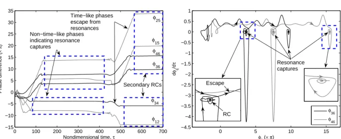
phase interactions occur between same frequency components (LF-LF or MF-MF). Resonance captures and escapes can be illustrated by the phase interactions in Fig. 5. An interesting observation is that the resonance captures between the heave and pitch modes occur ahead of those between the heave mode and NES, or those between the pitch mode and NES. This implies that in the first suppression mechanism there occur nonlinear modal energy exchanges between the heave and pitch modes (i.e., the
0 100 200 300 400 500 600 700 −15 −10 −5 0 5 10 15 20 25 30 35 Nondimensional time, τ Phase difference ( × π ) Non−time−like phases indicating resonance captures Time−like phases escape from resonances φ 12 φ 34 φ36 φ 46 φ 15 φ25 Secondary RCs 0 5 10 15 −4.5 −4 −3.5 −3 −2.5 −2 −1.5 −1 −0.5 0 0.5 1 φij (× π) d φij /d τ φ36 φ46 Resonance captures Escape RC
Figure 5: Analytical suppression mechanism via two-frequency averaging technique for the first mecha-nism shown in Fig. 2.
triggering mechanism15is activated) before TET to the NES (with the ensuing instability suppression) occurs. This early occurrence of RCs between the heave and pitch modes makes the repetition of suppressions and burst-outs in the first suppression mechanism possible.
3 EXPERIMENTAL STUDY
The nonlinear aeroelastic test apparatus (NATA) at Texas A&M University was de-veloped to experimentally test linear and nonlinear aeroelastic behavior. The low-speed wind tunnel with a 3ft width × 2ft height (0.91 × 0.51m) test section is a closed-circuit type with capacity of air speeds up to 45m/s. The device consists of a rigid NACA 0015 wing section capable of movement with two DOFs, pitch and heave (Fig. 6 (a)).
Experiments using the NATA are conducted at very low speeds and at very low reduced frequency. The wing section spans the entire wind tunnel, so the flow can be considered two-dimensional. For this flow environment, lift and drag can be modeled with quasi-steady aerodynamics. This type of aerodynamic model has provided very good agreement with NATA experimental results in the past, which can be referred to for the NATA parameters.4, 5
For the first proof-of-concept experiments with an NES in an aerodynamic application, the design goals were similar to what would be desired of flight hardware, tempered by the realities of the laboratory environment and the scale of the test program. It was expected to design a light-weight, passive, self-contained attachment that would signif-icantly improve the dynamic response of the NATA under typical operating conditions. On the basis of previous studies,10, 18 values of the stiffness and damping were selected, then refined through a series of numerical simulations, carried out using MATLAB.
(a) NATA in a low-speed wind tunnel Ungrounded NES car Wing specimen (NACA 0015) Force transducer Air track Linear encoder for NES Dashpot Connecting rod Structural support of NATA Wire 0 0.5 1 Heave, h (cm)
LCO suppression results with h(0)= 1.905cm (0.75"): Weak stiffness
8 9 10 11 12 13 0 0.05 0.1 0.15 0.2 Flow speed, U (m/s) Pitch, α (rad) U=10m/s U=11m/s U=12m/s U=13m/s (Low damping)
U=10m/s U=11m/s U=12m/s U=13m/s
(High damping)
LCO w/o NES
Suppressed LCO with low damping
Suppressed LCO with high damping M3 M2 M3 M2 U=10m/s U=11m/s U=12m/s U=13m/s (Low damping)
U=10m/s U=11m/s U=12m/s U=13m/s
(High damping) M1 M1 M1 M2 −1 0 1 Heave, h (cm)
First suppression mechanism: U=11m/s and h(0)=1.905cm (0.75")
−0.15 0 0.15 Pitch, α (rad) 0 5 10 15 20 25 30 −4 −2 0 2 Time, t (s) NES, v (cm) (b) (c)
Figure 6: (a) Experimental setup for the NATA coupled to an NES; (b) typical experimental results for the NES with ms= 1.2kg, weak essentially-nonlinear stiffness, and all zero initial conditions except for
h(0) = 1.905cm (=0.75in). The solid lines with square symbol indicate the LCO responses of the NATA
when the NES is not applied; the dashed lines with triangles (the dotted lines with circles) represent for the suppressed LCOs when low (high) damping is used. M 1, M 2, and M 3 denote the first, second, and third suppression mechanisms of LCOs, respectively. Amplitude modulations are denoted by a line between two ‘+’ symbols; (c) typical aeroelastic responses of the wing exhibiting recurring suppressed burst-outs.
A typical experimental bifurcation diagram with the standard NES10, 18 is presented in Fig. 6 (b). The dashed lines with triangles represent the results with this typical NES parameters. The flutter speed is significantly increased from 9m/s to 11m/s (22% improvement). Moreover, transitions appear sequentially from the third to second sup-pression mechanism.
Figure 6 (c) depicts the first suppression mechanism observed when the flow speed U = 11m/s, and the NES of a lighter mass, weaker stiffness and higher damping was applied. As in the theory, both the aeroelastic modes and the NES exhibit a nonlinear beating phenomenon; i.e., recurring burst-outs and suppressions of aeroelastic instability. The frequency ratio of the two aeroelastic modes exhibits 1:1 relation around 2–3 Hz by counting the number of waves per a second. On the other hand, the frequency ratio between the NES and heave (or pitch) mode becomes a 1:2 (or 1:3) subharmonic.
This observation can suggest that this first suppression mechanism dominantly consists of recurring (or transient) subharmonic resonance captures between the NES and aeroe-lastic modes, while the two aeroeaeroe-lastic modes are continually in 1:1 internal resonance exchanging the respective modal energy.
4 CONCLUSIONS
Suppressing aeroelastic instability (or LCO) in a 2-DOF in-flow rigid wing by means of passive targeted energy transfers (TETs) was investigated. The three distinct mechanisms for LCO suppression were identified both in theory and experiments: recurrent burst-outs and suppression, partial and complete suppressions. It was found that the passive TETs are activated by transient resonant interactions between the NES and the aeroelastic modes. Finally, it should be noted that a good understanding of the LCO triggering mechanism is key to applying the NES to efficiently suppress self-excited instabilities. ACKNOWLEDGMENTS
This work was supported by the US Air Force Office of Scientific Research through Grant Number FA9550–04–1–0073. GK is supported by a grant from the Belgian National Science Foundation, which is gratefully acknowledged.
REFERENCES
[1] C. Denegri, Limit Cycle Oscillation Flight Test Results of a Fighter with External Stores, Journal of Aircraft, 37, 761–769 (2000).
[2] R. Bunton and C. Denegri, Limit Cycle Oscillation Characteristics of Fighter Air-craft, Journal of AirAir-craft, Engineering Notes, 37,916–918 (2000).
[3] E. Dowell, J. Edwards and T. Strganac, Nonlinear Aeroelasticity, Journal of Aircraft, 40, (2003).
[4] J. Ko, A. Kurdila and T. Strganac, Nonlinear Control of a Prototypical Wing Section with Torsional Nonlinearity, Journal of Guidance, Control, and Dynamics, 20, 1181– 1189 (1997).
[5] G. Platanitis and T. Strganac, Control of A Wing Section with Nonlinearities Us-ing LeadUs-ing and TrailUs-ing Edge Control Surfaces, Journal of Guidance, Control and Dynamics, 27, 52–58 (2004).
[6] A. Vakakis and O. Gendelman, Energy Pumping in Coupled Mechanical Oscillators, Part II: Resonance Capture, Transactions of the ASME, Journal of Applied Mechan-ics, 68, 42–48 (2001).
[7] A. Vakakis, D. M. McFarland, L. Bergman, L. Manevitch and O. Gendelman, Isolated Resonance Captures and Resonance Capture Cascades Leading to Single- or Multi-Mode Passive Energy Pumping in Damped Coupled Oscillators, Transactions of the ASME, Journal of Vibration and Acoustics, 126, 235–244 (2004).
[8] Y. Lee, G. Kerschen, A. Vakakis, P. Panagopoulos, L. Bergman and D. M. McFarland, Complicated Dynamics of a Linear Oscillator with a Light, Essentially Nonlinear Attachment, Physica D, 204, 41–69 (2005).
[9] G. Kerschen, Y. Lee, A. Vakakis, D. M. McFarland and L. Bergman, Irreversible Passive Energy Transfer in Coupled Oscillators with Essential Nonlinearity, SIAM Journal on Applied Mathematics, 66, 648–679 (2006).
[10] J. Kowtko, Experiments with Nonlinear Energy Sinks: A Novel Approach to Vi-brational Energy Dissipation, Master’s thesis, University of Illinois at Urbana-Champaign (2005).
[11] D. M. McFarland, L. Bergman and A. Vakakis, Experimental Study of Non-Linear Energy Pumping Occurring at a Single Fast Frequency, International Journal of Non-Linear Mechanics, 40, 891–899 (2005).
[12] Y. Lee, A. Vakakis, L. Bergman and D. M. McFarland, Suppression of Limit Cycle Oscillations in the van der Pol Oscillator by Means of Passive Nonlinear Energy Sinks (NESs), Structural Control and Health Monitoring, 13, 41–75 (2006).
[13] Y. Lee, A. Vakakis, L. Bergman and D. M. McFarland and G. Kerschen, Suppression of Aeroelastic Instability with a Nonlinear Energy Sink: Theory (AIAA 2006–1849), 47th AIAA/ASME/ASCE/AHS/ASC Structures, Structural Dynamics, and Materi-als Conference, Newport, Rhode Island, 1–4 May 2006.
[14] W. Hill, T. Strganac, C. Nichkawde, D. M. McFarland, G. Kerschen, Y. Lee, A. Vakakis and L. Bergman, Suppression of Aeroelastic Instability with a Nonlinear Energy Sink: Experimental Results (AIAA 2006–1848), 47th AIAA/ASME/ASCE/AHS/ASC Structures, Structural Dynamics, and Materials Conference, Newport, Rhode Island, 1–4 May 2006.
[15] Y. Lee, A. Vakakis, L. Bergman and D. M. McFarland and G. Kerschen, Triggering Mechanisms of Limit Cycle Oscillations in a Two-degree-of-freedom Wing Flutter Model, Journal of Fluids and Structures, 21, 485–529 (2005).
[16] Y. Kuznetsov, Elements of Applied Bifurcation Theory, Springer-Verlag, New York (1995).
[17] L. Manevitch, The Description of Localized Normal Modes in a Chain of Nonlin-ear Coupled Oscillators using Complex Variables, NonlinNonlin-ear Dynamics, 25, 95–109 (2001).
[18] D. M. McFarland, G. Kerschen, J. Kowtko, Y. Lee, L. Bergman and A. Vakakis, Experimental Investigation of Targeted Energy Transfers in Strongly and Nonlinearly Coupled Oscillators, The Journal of the Acoustical Society of America, 118, 791–799 (2005).