Open Archive TOULOUSE Archive Ouverte (OATAO)
OATAO is an open access repository that collects the work of Toulouse researchers and
makes it freely available over the web where possible.
This is an author-deposited version published in :
http://oatao.univ-toulouse.fr/
Eprints ID : 13762
To link to this article : doi:
10.1016/j.powtec.2014.02.040
URL :
http://dx.doi.org/10.1016/j.powtec.2014.02.040
To cite this version : Barthe, Laurie and Philippot, Karine and
Chaudret, Bruno and Le Bolay, Nadine and Hemati, Mehrdji
Nanoparticles deposit location control on porous particles during dry
impregnation in a fluidized bed. (2014) Powder Technology, vol. 257.
pp. 198-202. ISSN 0032-5910
Any correspondance concerning this service should be sent to the repository
administrator:
[email protected]
Nanoparticles deposit location control on porous particles during dry
impregnation in a fluidized bed
Laurie Barthe
a, Karine Philippot
b, Bruno Chaudret
b, Nadine Le Bolay
a, Mehrdji Hemati
a,⁎
aUniversité de Toulouse, Laboratoire de Génie Chimique, UMR CNRS 5503, INP-ENSIACET, 4, allée Emile Monso BP 84324, Toulouse Cedex 04, France bLaboratoire de Chimie de Coordination, UPR CNRS 8241, 205 route de Narbonne, 31077 Toulouse Cedex 04, France
a b s t r a c t
Keywords: Metallic nanoparticles Fluidized bed Dry impregnation Deposit location DryingThis work deals with the synthesis of composite materials, catalytic or not, by an innovating technique named dry impregnation in a fluidized bed. This process permits the obtainment, in only one apparatus, of composite mate-rials which, by the traditional way, must successively undergo the stages of impregnation, filtration, drying and calcination/activation. Its principle consists in the spraying of a solution containing a metallic precursor into a hot fluidized bed of porous particles as a chosen support. After the impregnation step, the decomposition of metallic precursor and metal activation can be operated in the same reactor. It is found that the competition between two phenomena (drying and capillary) controls the deposit location.
This paper presents experimental results obtained during the dry impregnation of coarse and fine porous parti-cles using different types of precursors: inorganic precursors (metallic salts), metal organic complexes and a col-loidal suspension containing preformed metallic nanoparticles (rhodium). The effect of drying parameters (solvent content in gas phase and temperature) on deposit distribution within the support grains at the local scale is examined.
It appeared that a fast drying leads to a deposit located only at the external particle surface (similar to a surface coating), whereas a uniform deposit on the whole particle volume is obtained with slow drying conditions. It in-dicates that dry impregnation in fluidized beds is very flexible and, by a simple modification of the operating con-ditions, we can fix the deposit location.
1. Introduction
Usually, the preparation method of composite materials such as sup-ported catalysts consists in the immersion of the chosen support in a precursor solution under stirring to favour the diffusion inside the sup-port grains. After this impregnation, the composite material successive-ly undergoes the stages of filtration, drying and calcination/activation. This technique is easy to carry out but presents a weakness: the depen-dence of the deposit location on the physico-chemical properties of the solution-support couple. Indeed, a control of the deposit location repre-sents a real challenge, particularly in catalysis[1,2]. Moreover, to obtain a high metal loading, these four steps should be repeated several times. Supported catalyst synthesis can also be achieved using an innovat-ing technique, namely dry impregnation in a fluidized bed[3]. This tech-nique is a “one pot process”. It consists in spraying a precursor solution into a hot fluidized bed of porous particles.
During operation, the pulverised solution penetrates inside the po-rous support by capillarity (liquid spreading/penetration), and at the same time the solvent is evaporated thanks to the energy brought by the fluidization gas (drying). These phenomena depend on:
• The process related variables (fluidization gas flow rate, bed temper-ature, atomizing gas and liquid flow rates, and atomizer location), • The physicochemical properties (liquid interfacial tension, liquid
vis-cosity, contact angle between solid and liquid, nature and texture of solid particles).
The interdependency between these two kinds of parameters deter-mines the product quality and the metal repartition into the porous particles.
Few studies are reported on the dry impregnation technique. Pre-vious works from our laboratory, concerning impregnation of porous particles with aqueous solutions of metallic salts, showed the feasi-bility of manufacturing catalysts by direct impregnation of porous support particles through the pulverization of metallic precursor so-lutions in a hot fluidized bed[4–7]. It was shown that, under the cho-sen operating conditions, the efficiency of the metal deposition is close to 100% and the metal loading is directly related to the operat-ing time and the liquid flow rate and concentration. It was found that the competition between the drying rate, depending on the process-related variables, and the capillary penetration rate, depending on the physicochemical-related variables, controls the deposit location. A quasi uniform deposit inside the support particles is observed for soft drying. The metal nanoparticle size is controlled by the pore
⁎ Corresponding author.
E-mail address:[email protected](M. Hemati).
mean diameter of the support as well as the calcination operating protocol.
In order to determine the importance of the solvent evaporation process compared to the solution penetration by capillarity, an impreg-nation module, IM, was defined. It is the ratio between the drying char-acteristic time (tdry) and a capillary penetration time (tcap).
• tcap, the necessary time for liquid penetration in the pores, can be
estimated from the following equation taken from the model of the parallel capillary beam[8]:
tcap¼ 2μx
2
γLVðcosθÞ " rpore
ð1Þ where μ is the liquid viscosity, x the pore length equivalent to the ra-dius particle multiplied by the tortuosity factor, γLVthe interfacial
ten-sion, θ the contact angle and rporethe pore radius.
• tdryis the time necessary for a particle saturated by pure solvent to be
transformed into a dry particle under defined fluidized bed conditions (temperature and humidity). The calculation of this characteristic time is based on the mass and energy balances on a single wet particle considering that the mass transfer is controlled by external resistance (gas phase). The model's equations described in previous works[3,9]
lead to the following equation: tdry¼ dpχρs
6kyYi−Y − ð2Þ
where dpis the particle diameter, χ the internal support porosity, ρs
the solvent density, kythe overall mass transfer coefficient, Y
−
the average solvent content in the bed atmosphere determined by overall mass balance on the reactor, and Yithe absolute solvent content at the
interface (depending on the particle temperature and humidity). Moreover, another criterion depending on Y −and bed temperature was considered: ζs, the solvent vapour saturation rate value. It is defined as the ratio between gas solvent content in the bed and its value at sat-uration (satsat-uration solvent content).
Different feasibility tests carried out in our laboratory at soft, inter-mediate and fast drying conditions have shown that:
• For high ζs (0.8 ≤ ζs ≤ 1) and high IM, an undesirable phenomenon of partial or complete bed defluidization (wet quenching) is observed. • For slow drying conditions (0.2 ≤ ζs ≤ 0.8 and IM greater than 10), the
metallic precursor deposit is located inside the porous matrix. • For fast drying conditions (ζs b 0.2 and IM less than 10), the deposit is
located on the support particle surface.
This study concerns the effect of drying parameters (solvent content in gas phase and temperature) on deposit distribution within the com-posite materials. The experiments are carried out using various types of precursors (metallic salts, metal organic precursor solutions and colloi-dal suspensions containing preformed metal nanoparticles) and various particle sizes (from 100 μm to a few millimetres).
2. Methods and materials 2.1. Supports and metal sources
Two solids, different in their nature and grain size, were used as cat-alyst supports: fine porous silica particles and coarse activated γ alumi-na particles. Their principal physical properties are reported inTable 1.
Various types of precursors were sprayed on the supports. Aqueous solutions of metallic salts were prepared by dissolution of inorganic salts in water. Two precursors were used: iron nitrate Fe(NO3)3·9H2O and manganese nitrate Mn(NO3)2·4H2O. The
concentrations are indicated inTable 2. These precursors are very water soluble. The saturation concentration at 20 °C is respectively 300 g of crystals/100 g of water and 322 g of crystals/100 g of water.
Metal organic precursor solutions were prepared with an organome-tallic complex as precursor such as PdCl(η3-C
3H5)]2(palladium allyl
chloride). The most suitable solvent permitting the obtainment of a so-lution from the complex is tetrahydrofuran (THF). This solvent must be distilled and degassed before use to remove traces of peroxides, oxygen, and water to ensure the stability of the solution during the impregna-tion step.
Colloidal aqueous suspensions containing rhodium (0) colloids were prepared as previously described[10]. More precisely, sodium boro-hydride was added to an aqueous solution containing the surfactant HEA16Cl (N,N-dimethyl-N-cetyl-N-(2-hydroxyethyl)ammonium salts). This solution was quickly added under vigorous stirring to an aqueous so-lution of the precursor RhCl3·3H2O. The initial red solution darkened
im-mediately attesting that an aqueous Rh0 colloidal suspension is obtained, which remains stable for a long time. The average rhodium particles size is around 2.4 nm.
2.2. Experimental set-up
Depending on the metal source nature, the experiments were carried out under air or controlled atmosphere (inert or reductive) in a batch fluidized bed (Fig. 1). This reactor is a stainless steel cylindrical column with 0.1 m inner diameter and 0.5 m height, described by Barthe[7].
The gas distributor is a stainless steel perforated plate with a poros-ity of 0.5%. The fluidizing gas flow rate is measured by means of a rota-meter and preheated by an electrical heater before entering the bed. The elutriated particles and solvent vapours are collected at the column out-let respectively by a cyclone and a condenser.
The metallic precursor solution is drawn up by a volumetric pump from a reservoir to an internal mixing of two-fluid spray nozzle. The at-omizing gas flow rate is controlled by a needle valve and measured by a rotameter. The bed temperature is controlled by means of a PID regula-tor. Monitoring of temperature and pressure drop takes place during operation.
The solid sampling system is achieved with a vacuum circuit. The sampling with a controlled atmosphere is done through a nitrogen cir-cuit. In addition it enables working with oxygen and water sensitive products.
2.3. Characterization methods
The metal deposit location of the samples was studied using differ-ent techniques. The composite materials were analysed by an optical microscope and a Transmission Electron Microscope (TEM). In the case of TEM observations, the samples were cut by ultramicrotomy. 2.4. Operating conditions
The different operating conditions are listed inTable 2. The first six experiments were carried out with inorganic precursors. Organometal-lic complexes have been used in experiment S7 while a colloidal sus-pension was sprayed for experiments S8 and S9. For each precursor type various experiments were carried out with different values of IM
Table 1
Physical properties of the porous supports.
Properties Silica gel Alumina
Mean diameter d50 dp(μm) 120 2 400
Specific surfaces Sbet(m2/g) 530 330
Pore volume Vp(cm3/g) 0.8 0.3
Particle density ρ (kg/m3) 910 2 200
and ζs corresponding to the three zones previously defined: unstable operation (partial or complete bed defluidization), soft drying and fast drying. The pure solvent used is water except for experiment S7 for which tetrahydrofuran (THF) was used since the corresponding precur-sor is water sensitive.
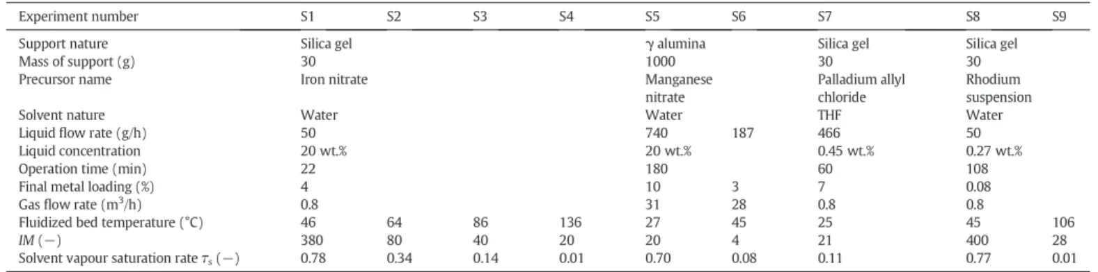
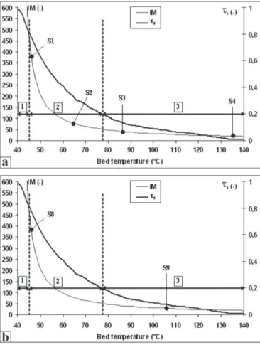
The operating condition choice to obtain various deposit location of the precursor in the support can be done very easily. The experiments should be carried out keeping the same solution and fluidization gas flow rate, modifying only the bed temperature. It is the case of experi-ments S1 to S4 (for iron deposit) and experiexperi-ments S8 and S9 (for rhodi-um deposit). The evolutions of the characteristic times and the solvent content in bed atmosphere versus bed temperature are obtained using the model's equations described in previous works[3,9]. These theoret-ical results permit the determination of the influence of temperature on the characteristic parameters ζs and IM (Fig. 2a and b). The graph can be divided into the three zones previously described: unstable (1), slow drying (2) and fast drying (3).
According to the operating conditions and to the values of ζs and IM, the experiments S1 to S4 can be symbolized on the graph ofFig. 2a. It is possible to confirm the operation conditions and predict the deposit lo-cation through the choice of the bed temperature. The same can be done for experiments S8 and S9 (Fig. 2b).
3. Results and discussion
The deposit location of palladium-, iron- and manganese-composite materials was studied after an activation step leading to the forma-tion of metallic nanoparticles. In the case of organometallic precur-sor (palladium) the activation step is operated under a nitrogen/ hydrogen mixture at 80 °C during 90 min, while for inorganic precursors the samples are heated up in air to 450 °C (for iron) or to 300 °C (for manganese). Activation and calcination conditions were chosen to favour the formation of easily observable metallic nanoparticles clusters. These conditions were not optimized to ob-tain small individual nanoparticles[11]. In the case of rhodium composite materials, the deposit is already formed by metallic nanoparticles.
3.1. Unstable conditions
A few experiments were carried out in “unstable conditions” (ζs N 0.8) in the case of iron nitrate spraying on fine porous silica particles. It was verified that these experiments could not be com-pleted due to partial or complete bed defluidization (wet quenching).
Table 2
Experimental conditions.
Experiment number S1 S2 S3 S4 S5 S6 S7 S8 S9
Support nature Silica gel γ alumina Silica gel Silica gel
Mass of support (g) 30 1000 30 30
Precursor name Iron nitrate Manganese
nitrate
Palladium allyl chloride
Rhodium suspension
Solvent nature Water Water THF Water
Liquid flow rate (g/h) 50 740 187 466 50
Liquid concentration 20 wt.% 20 wt.% 0.45 wt.% 0.27 wt.%
Operation time (min) 22 180 60 108
Final metal loading (%) 4 10 3 7 0.08
Gas flow rate (m3/h) 0.8 31 28 0.8 0.8
Fluidized bed temperature (°C) 46 64 86 136 27 45 25 45 106
IM (−) 380 80 40 20 20 4 21 400 28
Solvent vapour saturation rate τs(−) 0.78 0.34 0.14 0.01 0.70 0.08 0.11 0.77 0.01
3.2. Slow drying conditions
Some of the experiments were carried out under operating condi-tions corresponding to slow drying (0.2 ≤ ζs ≤ 0.8 and high IM) using inorganic precursors (S1, S2 and S5) and a colloidal suspension (S8).
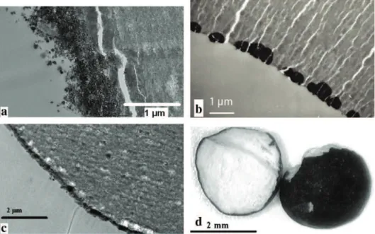
The samples S1 and S8 were analysed by TEM (Fig. 3a and b). The micrographs show that the deposit, characterized by the most darkened zones, is quasi uniform in the entire particle volume in the case of iron nanoparticles (a) and rhodium nanoparticles (b). In slow drying conditions, whatever the precursor nature, dry impregnation on fine porous particles leads to homogeneous deposit.
Thus, experiment S5 was carried out with coarse alumina particles to verify if this result, obtained with fine particles, is similar with bigger particles. Samples were prepared by spraying an inorganic precursor on coarse alumina particles. Three samples were removed from the flu-idized bed at different operation times to characterize the evolution of the deposit distribution during the impregnation. They are numbered from S5.1 to S5.3, in ascending order of time residence in the bed and so of the metal deposit quantity. The cross section photographs are pre-sented inFig. 4.
These images show that the aqueous solution penetrates into the alumina particles. Moreover, the precursor deposit inside the solid is similar to the displacement of a front from the particle periphery to-wards its centre (S5.1 to S5.3). This internal position of the impregna-tion front is a funcimpregna-tion of the impregnaimpregna-tion rate. For S5.1 and S5.2, the precursor is rather on the particle borders (egg shell catalysts). For S5.3, the precursor reaches the particle centre. The deposit is then uni-form in the whole particle volume. Nearly constant concentration was detected on the section of the sample by Scanning Electron Microscopy coupled with Energy Dispersive X-ray. This phenomenon is comparable to a heterogeneous reaction between a gas and a porous solid when the
diffusion penetration time of the reactive gas is very high compared to the chemical reaction time. In this case, the reaction proceeds following a shrinking core model developed in a previous article[12].
3.3. Fast drying conditions
The other experiments were carried out under fast drying conditions (ζs b 0.2 and low IM) using inorganic precursors (S3, S4 and S6), an or-ganometallic precursor (S7) and a colloidal suspension (S9).
Fig. 2. IM and τsevolution with the bed temperature (a: iron deposit; b: rhodium deposit).
Fig. 3. TEM micrographs of various metallic nanoparticles on silica; a) iron (S1); b) rhodi-um (S8).
Fig. 4. Microscope micrographs of manganese deposit on alumina particles at different op-erating times (S5): S5.1 corresponds to 30 min, S5.2 to 90 min and S5.3 to 170 min.
Samples obtained for experiments S4, S7 and S9 were analysed by TEM (Fig. 5a, b and c). For each micrograph a deposit at the particle sur-face is observed, similar to a sursur-face coating. The thickness of this coat can be controlled by the precursor quantity (and thus by the operation time) and is composed of individual nanoparticles into clusters. In fast drying conditions, whatever the precursor nature, the deposit is located at the silica particle surface.
To verify again that the conclusion obtained with fine particles can be extended to coarse particles, experiment S6 was carried out. S6 was analysed by microscopy. For fast drying conditions, micrographs of the external surface and the cross section of the samples presented inFig. 5d reveal that the deposit is located at the particle surface, with the intermediate and central zones remaining virgin.
4. Conclusion
In this paper, the synthesis of metal based-composite materials obtained by dry impregnation in a fluidized bed using different types of precursors is described. These precursors are inorganic precursors (metallic salts), metal organic complexes and a colloidal suspension containing preformed metallic nanoparticles (rhodium). The effect of operating parameters, solvent content in gas phase and bed temperature, on deposit distribution within the grains at the local scale is examined.
The results show that by correctly choosing operating conditions, the deposit location can be oriented. In addition, the impregnation of porous inorganic support by a colloidal suspension was also a success. A key operating parameter depending on the bed temperature and the solvent content in gas phase was defined: ζs, the solvent vapour satura-tion rate. Three operasatura-tion condisatura-tions are distinguished:
• Unstable operation (partial or complete bed defluidization), for high ζs (0.8 ≤ ζs ≤ 1). In this zone a low increase of the liquid flow rate or a reduction of the gas inlet temperature can lead to wet quenching.
• “Soft drying conditions” are characterized by intermediate values of ζs (0.2 ≤ ζs ≤ 0.8) and IM greater than 10. The solid precursor de-posit takes place homogeneously inside the particles.
• “Fast drying conditions” are characterized by high bed tempera-tures and low solvent saturation rates (ζs b 0.2). The deposit is then located on the particle external surface (egg shell catalysts).
Moreover, all results show that the deposit location can be con-trolled during the dry impregnation process whatever the precursor na-ture (organic, inorganic or colloidal suspension) and for a large range of support particle sizes (from 100 μm to a few millimetres).
Acknowledgements
The authors would like to thank A. Roucoux and A. Denicourt-Nowicki from Institut des sciences chimiques de Rennes, team “Organométalliques: Matériaux et Catalyse” for their collaboration in synthesis of rhodium colloidal suspension.
References
[1]J.W. Fulton, Selecting the catalyst configuration, Chem. Eng. 93 (1986) 97–101.
[2] A. Lekhal, B. Glasser, J.G. Khinast, Impact of drying on catalyst profile of supported impregnation catalysts, Chem. Eng. Sci. 56 (15) (2001) 4473–4487.
[3]L. Barthe, S. Desportes, M. Hemati, K. Philippot, B. Chaudret, Synthesis of supported cat-alysts by dry impregnation in fluidized bed, Chem. Eng. Res. Des. 85 (A6) (2007) 1–11.
[4] M. Hemati, D. Steinmetz, B. Chaudret, K. Philippot, Fabrication de catalyseur d'un nouveau type par imprégnation en lit fluidise, Brevet EPI-PCT/FR 02/01795, 2001.
[5]M. Hemati, R. Cherif, K. Saleh, V. Pont, Fluidized bed coating and granulation: influ-ence of process-related variables and physicochemical properties on the growth ki-netics, Powder Technol. 130 (2003) 18–34.
[6]S. Desportes, D. Steinmetz, M. Hemati, K. Philippot, B. Chaudret, Production of sup-ported asymmetric catalysis in a fluidized bed, Powder Technol. 157 (2005) 12–19.
[7]L. Barthe, Synthèse et dépôt de nanoparticules métalliques dans un support poreux par imprégnation en voie sèche cdans un lit fluidisé: élaboration de catalyseurs supportés, (PhD thesis) INP, Toulouse, 2007.
[8]N.T. Burdine, Relative permeability calculations from pore size distribution data, Pet. Trans. Am. Inst. Min. Eng. 198 (1953) 71–77.
[9]S. Desportes, Imprégnation en voie sèche en lit fluidisé: application à la synthèse de catalyseurs supportés, (PhD thesis) INP, Toulouse, 2005.
[10] J. Schulz, A. Roucoux, H. Patin, Chem. Eur. J. 6 (4) (2000) 618–624.
[11] L. Barthe, M. Hemati, K. Philippot, B. Chaudret, Dry impregnation in fluidized bed: drying and calcination effect on nanoparticles dispersion and location in a porous support, Chem. Eng. Res. Des. 86 (4) (2008) 349–358.
[12] L. Barthe, S. Desportes, D. Steinmetz, M. Hemati, Metallic salt deposition on porous particles by dry impregnation in fluidized bed: effect of drying conditions on metal-lic nanoparticles distribution, Chem. Eng. Res. Des. 87 (2009) 915–922.