Organic Additives in Zinc Electrowinning and
Electrodeposition of Fe-Mo-P Alloys as
Cathodes for Chlorate Production
Mémoire
NABIL SOROUR
Maîtrise en génie des matériaux et de la métallurgie
Maître ès sciences (M.Sc.)
Québec, Canada
Organic Additives in Zinc Electrowinning and
Electrodeposition of Fe-Mo-P Alloys as
Cathodes for Chlorate Production
Mémoire
NABIL SOROUR
Sous la direction de :
Résumé
Ce projet de travail est divisé en deux études principales: (a) l'influence des certains additifs organiques sur la consommation d'énergie et la pureté du métal de zinc déposé dans le processus d'extraction électrolytique, et (b) l’électrodéposition des alliages binaires et ternaires de Fe-Mo et Fe-Mo-P sur des substrats d’acier doux afin d’agir comme cathodes pour la production de chlorate.
(a) Parmi les sept différents additifs organiques examinés, les sels des liquides ioniques ont réussi à augmenter le rendement du courant jusqu'à 95,1% comparé à 88,7% qui a
obtenu à partir de l'électrolyte standard en présence des ions de Sb3+. La réduction
maximale de la consommation d'énergie de ~173 kWh tonne-1 a été obtenue en ajoutant de
3 mg dm-3 du chlorure de 1-butyl-3-méthylimidazolium dans le même électrolyte. La teneur
en plomb dans le dépôt de zinc est réduite de 26,5 ppm à 5,1-5,6 ppm en utilisant les sels des liquides ioniques.
(b) Des différents binaires Fe-Mo et ternaires Fe-Mo-P alliages ont été électrodéposés sur des substrats d’acier doux. Les alliages préparés ont une tenure en Mo entre 21-47 at.% et une tenure en P de 0 à 16 at.%. L'activité électrocatalytique de ces alliages vers la réaction de dégagement d'hydrogène (RDH) a été étudiée dans des solutions de chlorure de sodium. La réduction maximale de la surtension de RDH de ~313 mV a été obtenue par l’alliage ternaire préparé Fe54Mo30P16 par rapport à celle obtenue pour l'acier doux. La
rugosité de surface et l'activité intrinsèque des revêtements de Fe-Mo-P peuvent être l'origine du comportement prometteur de ces électrocatalyseurs vers la RDH.
Abstract
This work project is divided into two main studies: (a) the influence of certain organic additives on the power consumption and the purity of deposited zinc during electrowinning process, and (b) the electrodeposition of binary and ternary alloys of Fe-Mo and Fe-Mo-P on mild steel substrates to act as cathodes for chlorate production.
(a) Among seven different examined organic additives, the ionic liquid salts succeeded to increase the current efficiency up to 95.1% compared to 88.7% obtained from standard
electrolyte in presence of Sb3+ ions. Maximum reduction of power consumption of ~173
kWh ton-1 was observed by addition of 3 mg dm-3 of 1-butyl-3-methylimidazolium chloride
to the same electrolyte. Lead content in the zinc deposit is reduced from 26.5 ppm to 5.1-5.6 ppm by using the ionic liquid salts.
(b) Different binary Fe-Mo and ternary Fe-Mo-P alloys have been electrodeposited on
mild steel substrates. The prepared alloys have Mo content between 21-47 at.% and P content from 0 to 16 at.%. The electrocatalytic activity of these alloys towards the hydrogen evolution reaction (HER) was investigated in sodium chloride solutions. The maximum reduction of HER overpotential of ~313 mV was achieved from the prepared ternary alloy Fe54Mo30P16 compared to that obtained from mild steel. The surface roughness and intrinsic
activity of Fe-Mo-P coatings could be the origin of the promising behavior of these electrocatalysts towards the HER.
Table of Content
Résumé ... iii
Abstract ... iv
Table of Content ... v
List of Tables ... ix
List of Figures ... xi
Acknowledgments ... xv Forward ... xvi CHAPTER 1 ... 1 INTRODUCTION ... 1 1.1. Background ... 2 1.2. Zinc Electrowinning ... 2 1.2.1. Zinc Metal ... 2
1.2.2. Methods of Extraction of Zinc Metal ... 3
1.2.3. Uses of Zinc ... 4
1.3. Electrodeposition of Alloys as Cathodes in Chlorate Production ... 5
1.3.1. Chlorate Production ... 5
1.3.2. Cathodes in Chlorate Production ... 6
1.4. Objectives and Detailed Approaches ... 7
1.4.1. Effect of Certain Organic Additives on Zinc Electrowinning Process ... 7
1.4.2. Performing the Electrodeposition of Fe-Mo & Fe-Mo-P Alloys as Cathodes ... 8
CHAPTER 2 ... 9
LITERATURE REVIEW ... 9
2.1. Zinc Electrowinning Process ... 10
2.1.1. Lead-Based Anodes ... 11
2.1.2. Corrosion of Lead-Based Anodes ... 12
2.1.3. Oxygen Overpotential of Lead-Based Anodes ... 13
2.1.4. Role of Manganese Ions in the Electrolyte ... 14
2.1.5. Surface Structure and Crystallographic Orientation... 16
2.1.6. Metallic Impurities in Zinc Electrowinning ... 17
2.1.6.1. Effect of Lead Impurity on Zinc Deposition ... 18
2.1.6.3. Effect of Copper, Nickel and Cobalt Impurities on Zinc Deposition ... 21
2.1.7. Additives in Zinc Electrowinning ... 23
2.1.7.1. Effect of Glue ... 23
2.1.7.2. Effect of Natural Products and Surfactants ... 25
2.1.7.3. Effect of Synthetic Polymers ... 26
2.1.7.4. Effect of Quaternary Ammonium Salts ... 27
2.1.7.5. Effect of Ionic Liquid Salts ... 28
2.2. Electrodeposition of Alloys as Cathodes for Chlorate Production ... 31
2.2.1. Chlorate Production ... 31
2.2.2. Mild Steel Cathodes ... 33
2.2.3. Fe-Based Alloys Cathodes ... 34
2.2.4. Ni-Based Alloys Cathodes ... 35
2.2.5. Molybdenum Co-deposition ... 37
2.2.6. Phosphorous Co-deposition ... 38
2.3. Electrochemical Test Methods (Approach and Evaluation) ... 40
2.3.1. Galvanostatic Polarization Technique ... 41
2.3.2. Potentiodynamic Polarization Technique ... 41
2.3.3. Cyclic Voltammetry Technique ... 43
2.3.4. Electrochemical Impedance Spectroscopy Technique ... 44
2.4. Summary ... 46
CHAPTER 3 ... 48
EXPERIMENTAL ... 48
3.1. Electrolyte and Set-up ... 49
3.1.1. Zinc Electrolyte and Materials Preparation ... 49
3.1.2. Fe-Mo & Fe-Mo-P Electrolytes and Materials Preparation ... 50
3.1.3. Set-up ... 51
3.2. Electrochemical Techniques and Measurements ... 52
3.2.1. Galvanostatic Polarization ... 52
3.2.2. Current Efficiency Calculations ... 52
3.2.3. Power Consumption Calculations ... 52
3.2.4. Potentiodynamic Polarization ... 53
3.2.5. Cyclic voltammetry ... 54
3.3. Deposit Examination Techniques ... 55
3.3.1. Scanning Electron Microscopy (SEM) ... 55
3.3.2. Energy Dispersive Spectroscopy (EDS) ... 55
3.3.3. X-ray Diffraction (XRD) ... 56
3.3.4. Inductively Coupled Plasma (ICP) ... 56
CHAPTER 4 ... 57
INFLUENCE OF DIFFERENT ORGANIC ADDITIVES IN ZINC ELECTROWINNING FROM ACIDIC SULPHATE ELECTROLYTE ... 57
Résumé ... 58
Abstract ... 59
4.1. Introduction ... 60
4.2. Experimental ... 61
4.2.1. Electrolyte and Experimental Setup ... 61
4.2.2. Deposit Examination ... 62
4.2.3. Potentiodynamic Polarization and Cyclic Voltammetry ... 62
4.3. Results and Discussion ... 63
4.3.1. Power Consumption and Current Efficiency ... 63
4.3.2. Characterization of Deposits ... 67
4.3.3. Potentiodynamic Polarization ... 70
4.3.4. Cyclic Voltammetry Measurements ... 73
4.4. Conclusions ... 77
CHAPTER 5 ... 79
ELECTROCHEMICAL STUDIES OF IONIC LIQUID ADDITIVES DURING THE ZINC ELECTROWINNING PROCESS ... 79 Résumé ... 80 Abstract ... 81 5.1. Introduction ... 82 5.2. Experimental ... 84 5.2.1. Electrolysis ... 84 5.2.2. Deposit Examination ... 85 5.2.3. Electrochemical Measurements ... 85
5.3. Results and Discussion ... 86
5.3.3. Deposit Examination ... 89
5.3.4. Polarization Studies ... 92
5.4. Conclusions ... 98
CHAPTER 6 ... 99
ELECTRODEPOSITION AND STUDY OF THE ELECTROCATALYTIC ACTIVITY OF Fe-Mo-P ALLOYS FOR HYDROGEN EVOLUTION DURING CHLORATE PRODUCTION ... 99
Résumé ... 100
Abstract ... 101
6.1. Introduction ... 102
6.2. Experimental ... 104
6.3. Results and Discussion ... 105
6.3.1. Deposit Characterization ... 105
6.3.2. Steady-State Polarization Curves ... 108
6.3.3. Electrochemical Impedance Spectroscopy ... 112
6.4. Conclusions ... 115
CHAPTER 7 ... 117
CONCLUSIONS AND OUTLOOK ... 117
7.1. Conclusions ... 118
7.2. Outlook ... 121
List of Tables
Table 2.1. Electrode potential (V/SCE) vs. current density (A m-2) of anodes from lead and its
alloys in 1.8 M H2SO4 at 30oC [30] ... 14
Table 2.2. Variation of current efficiency and preferred crystalline orientation of zinc deposit at
different concentrations of lead at 400 A m-2 and 35oC for zinc electrolyte of 55 g dm-3
Zn2+ + 150 g dm-3 H
2SO4 [37]... 18
Table 2.3. Variation of current efficiency and preferred crystalline orientation of zinc deposit at
different concentrations of antimony at 400 A m-2 and 35oC for zinc electrolyte of 55 g
dm-3 Zn2+ + 150 g dm-3 H
2SO4 [37] ... 20
Table 2.4. Effect of copper on current efficiency and crystal orientation of zinc deposit at different
concentrations and different current densities for electrolysis in 55 g dm-3 Zn2+, 150 g
dm-3 H
2SO4 at 35oC [43] ... 21
Table 2.5. Variation of current efficiency and preferred crystalline orientation of zinc deposit at
different concentrations of nickel at 400 A m-2 and 35oC for zinc electrolyte of 55 g dm -3 Zn2+ + 150 g dm-3 H
2SO4 [37] ... 22
Table 2.6. Effect of [BMIM]HSO4 and Gelatin on current efficiency and power consumption during
zinc electrodepsotion [70] ... 29
Table 2.7. Effect of Sb3+ on current efficiency in absence and in presence of [BMIM]HSO
4 during
zinc electrowinning [72] ... 31
Table 2.8. Kinetic parameters for the HER on the Ni-Cu-Fe electrode [88] ... 37 Table 3.1. Fe-Mo and Fe-Mo-P electrolytes compositions ... 50 Table 4.1. Effect of PAM, [BMIM]Cl, TBABr, BKCl and Chitin on cell voltage, CE and PC in
absence and in presence of Sb3+ during zinc electrodeposition for 2 h at 50 mA cm-2 and
38оC ... 65
Table 4.2. Effects of PAM, [BMIM]Cl, TBABr, BKCl and Chitin on surface morphology, crystal
orientation and lead contamination in absence and in presence of Sb3+ during zinc
electrodeposition for 2h at 50 mA cm-2 ... 67
Table 4.3. Effects of additives on Tafel slopes, cathodic overpotential at 50 mA cm-2 obtained from
potentiodynamic polarization versus Ag,AgCl/KCl(sat) and NOP obtained from cyclic
voltammetry ... 76
Table 5.1. Effect of gelatin, [EMIM]MSO3 and [BMIM]Br on CE and PC in absence and in
Table 5.2. Crystallographic orientations and lead concentration of zinc deposits obtained by adding
3mg of gelatin, [EMIM]MSO3 and [BMIM]Br in absence and in presence of Sb(III)
during zinc electrodeposition for 2h at 50 mA cm-2 ... 92
Table 5.3. Effect of [EMIM]MSO3, [BMIM]Br and gelatin on Tafel slopes, cathodic overpotential
at 50 mA cm-2, exchange current density and NOP ... 95
Table 6.1. The compositions of the coatings from four different electrolytes after 6 hours of
electrodeposition at 20 mA cm-2 and 30oC ... 106
Table 6.2. The measured kinetic parameters of HER for MS, Fe-Mo and Fe-Mo-P electrodes in
sodium chloride solution at 80oC and pH 6.4 ... 110
Table 6.3. The electrochemical data obtained by the Nyquist plots of MS, Mo and different
List of Figures
Figure 1.1. Typical roast-leach-electrowinning processes for zinc [7] ... 3
Figure 1.2. The major uses of zinc [13] ... 5
Figure 2.1. (a) Simple electrolysis cell for zinc (b) Aluminum cathodes deposited by zinc ... 11
Figure 2.2. Potential-pH diagram obtained according to the ionic activities in an actual anodic film for the Pb-H2O-H2SO4 system at 25oC (potential vs. SHE) [27] ... 12
Figure 2.3. Lead-based anode; (a) Before electrolysis and (b) After 5 hours of electrolysis ... 16
Figure 2.4. Zinc deposit shows HCP Lattice among the three most important lattices ... 17
Figure 2.5. SEM photomicrographs (X 385) showing the effect of current density on the morphology of zinc deposits from addition-free electrolyte using unconditioned Pb-Ag anodes. (a) 215 A m-2, 60 min, 0.125% Pb; (b) 323 A m-2. 60 min, 0.076% Pb; (c) 430 A m-2, 60 min, 0.04% Pb; (d) 538 A m-2, 60 min, 0.021% Pb; (e) 1076 A m-2, 30 min, 0.019% Pb; (f) 2152 A m-2, 15 min, 0.011% Pb [40] ... 19
Figure 2.6. SE micrographs showing the morphology of 6h zinc deposits electrowon at 500 A m-2 and 38oC from electrolytes containing; (a) and (b) 0.02, (c) and (d) 0.04 mg dm-3 Sb [42] ... 20
Figure 2.7. Quaternary ammonium salts; (a) Non-aromatic, (b) Aromatic ... 27
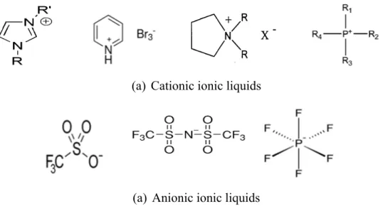
Figure 2.8. Examples of ionic liquids salts; (a) Cationic, and (b) Anionic ... 29
Figure 2.9. Schematic process of chlorate production (Chemetics Inc. B.C., Canada) ... 32
Figure 2.10. Scanning micrographs of developed cathodes [86] ... 36
Figure 2.11. Potentiodynamic polarization plot [110] ... 43
Figure 2.12. Theoretical cyclic voltammogram [102] ... 44
Figure 2.13. (a) Simple electrified electrode/electrolyte interface, (b) Electronic components for the same interface [112] ... 45
Figure 2.14. Nyquist impedance plot for the showed circuit for Rs, Rct and Cdl [114] ... 46
Figure 3.1. Schematic experimental set-up for three-electrode cell [116] ... 51
Figure 3.2. Electrolysis cell set-up ... 51
Figure 3.3. Polarization curve potential vs current density (log i) [119] ... 54
Figure 4.1. Effects of PAM, [BMIM]Cl, TBABr, BKCl and Chitin on current efficiency: (a) in absence of Sb3+ and (b) in presence of 0.0055 mg dm-3 of Sb3+ during zinc electrodeposition for 2h at 50 mA cm-2 and 38оC ... 66
Figure 4.2. Scanning electron micrographs (x1000) of zinc deposits in absence of Sb3+; (a) SE, (b) PAM, (c) [BMIM]Cl 3mg dm-3, (d) TBABr 3mg dm-3, (e) BKCl 3mg dm-3 and (f) Chitin 3mg dm-3 ... 68
Figure 4.3. Scanning electron micrographs (x1000) of zinc deposits in presence of 0.0055 mg of
Sb3+; (a) SE, (b) PAM 3mg dm-3, (c) [BMIM]Cl 3mg dm-3, (d) TBABr 3mg dm-3, (e)
BKCl 3mg dm-3 and (f) Chitin 3mg dm-3 ... 69
Figure 4.4. Effects of the additives on the cathodic polarization during zinc electrodeposition with
different concentrations in absence and in presnce of antimony; (a) PAM, (b)
[BMIM]Cl, (c) TBABr, (d) BKCl and (e) Chitin ... 73
Figure 4.5. Cyclic voltammograms during zinc electrowinning using aluminum cathode with
different concentrations of 0,1,5 and 40 mg dm-3 of: (a) PAM, (b) [BMIM]Cl, (c)
TBABr, (d) BKCl and (e) Chitin ... 75
Figure 5.1. Effect of gelatin, [EMIM]MSO3 and [BMIM]Br on CE: (a) in absence of Sb(III) and (b)
in presence of 0.0055 mg of Sb(III) during zinc electrodeposition for 2h at 50 mA cm-2
... 88
Figure 5.2. Scanning electron microscopy photomicrographs (x1000) of zinc deposit in absence of
Sb(III); (a) blank, (b) 3mg gelatin, (c) 3mg [EMIM]MSO3 and (d) 3mg [BMIM]Br ... 90
Figure 5.3. Scanning electron microscopy photomicrographs (x1000) of zinc deposit in presence of
0.0055mg of Sb(III); (a) blank, (b) 3mg gelatin, (c) 3mg [EMIM]MSO3 and (d) 3mg
[BMIM]Br ... 91
Figure 5.4. XRD patterns of zinc deposit in absence of Sb(III); (a) 3mg [EMIM]MSO3, (b) 3mg
[BMIM]Br ... 91
Figure 5.5. Effect of [EMIM]MSO3 on the cathodic polarization during zinc electrodeposition
using aluminum cathode with different concentrations; (a) in absence of Sb(III), (b) in presence of Sb(III) ... 94
Figure 5.6. Effect of [BMIM]Br on the cathodic polarization during zinc electrodeposition using
aluminum cathode with different concentrations; (a) in absence of Sb(III), (b) in
presence of Sb ... 94
Figure 5.7. Cyclic voltammograms of [EMIM]MSO3 during zinc electrodeposition using aluminum
cathode with different concentrations; (a) in absence of Sb(III), (b) in presence of Sb(III) ... 96
Figure 5.8. Cyclic voltammograms of [BMIM]Br during zinc electrodeposition using aluminum
cathode with different concentrations; (a) in absence of Sb(III), (b) in presence of Sb(III) ... 97
Figure 6.1. Scanning electron micrographs (X500) of deposits; (a) Fe53Mo47, (b) Fe70Mo21P9, (c)
Fe61Mo26P13, (d) Fe54Mo30P16 after electrodeposition during 6 hours at 20 mA cm-2 at
Figure 6.2. XRD spectra of Fe-Mo and Fe-Mo-P deposits obtained from electrodeposition of 6
hours at 20 mA cm-2 and 30oC ... 108
Figure 6.3. Polarization curves of Fe-Mo and three Fe-Mo-P deposited electrodes compared to MS
in chlorate solution at 80oC and pH 6.4 ... 109
Figure 6.4. The electrical equivalent circuit used for simulation of the impedance spectra for the
HER [171] ... 112
Figure 6.5. The Nyquist plots for the HER process on a) MS, b) Fe53Mo47, c) Fe70Mo21P9, d)
“To my kind mother and the memory of my great father.
Acknowledgments
I would like to express my deepest appreciation to my supervisor Prof. Edward Ghali for giving me the opportunity to work on such interesting subject also for his valuable advices and guidance. His dedication and diligent work ethics are always my inspiration during this study.
I wish to acknowledge Dr. Georges Gabra for his advices and participation during choosing the working materials and their testing. Sharing his experience with me was really valuable. Dr. Fariba Safizadeh and Dr. Wei Zhang are gratefully acknowledged for their support, assistance, and contribution during this work. I’m really thankful to Mr. Georges Houlachi for his insightful comments and valuable contribution.
Zinc Électrolytique du Canada (CEZinc) Limitée, Hydro-Québec, and Natural Sciences and Engineering Research Council of Canada (NSERC) are gratefully acknowledged for their financial support.I would like also to thank Mrs. Vicky Dodier, Mr. André Ferland, Mr. Jean Frenette, and Mr. Alain Brousseau for their professional technical participation. Kind help, friendships, and ideas of Deniz Bas, Chaoran Su, and Ramzi Ishak, are really appreciated.
Forward
This thesis is composed of seven chapters and presented as articles insertion form. The first chapter provides a brief introduction of two main electrometallurgical processes; the electrowinning of zinc, and the electrodeposition of cathodes in chlorate production. In the second chapter, a targeted literature review covers the previous studies concerning the problems in zinc electrowinning process such as the metallic impurities also the beneficial effect of organic additives on this process. Chapter two discusses as well the utilization of different electrodeposited cathodes in the chlorate industry and their effect on hydrogen evolution reaction overpotential. The experimental steps and conditions are explained in chapter three. Chapters four, five, and six present the results of this work in the form of three scientific papers as the following:
Chapter four
Influence of Different Organic Additives on Zinc Electrowinning from Acidic Sulphate Electrolyte
N. Sorour1,*, W. Zhang1, G. Gabra1, E. Ghali1, and G. Houlachi2
1Department of Mining, Metallurgical and Materials Engineering, Laval University,
Québec, Canada, G1V 0A6.
2Hydro-Québec research centre (LTE), Shawinigan, QC, Canada, G9N 7N5.
This paper was presented in the 54th annual Conference of Metallurgists - COM, Toronto,
Canada (Aug. 23-26, 2015) and published in the proceeding by Canadian Institute of Mining, Metallurgy and Petroleum. CIM-COM, paper #8986 pp 1-13, ISBN: 978-1-926872-32-2.
In this work, different five additives from different organic groups have been studied in the zinc electrowinning process. The experimental measurements and analysis along with paper writing and presentation were performed by the first author. The scientific revision was done by Dr. W. Zhang, Dr. G. Gabra, and Prof. E. Ghali. The project was supervised by Prof. E. Ghali and Mr. G. Houlachi.
Chapter five
Electrochemical Studies of Ionic Liquid Additives during the Zinc Electrowinning Process
N. Sorour1,*, W. Zhang1, G. Gabra1, E. Ghali1, and G. Houlachi2
1Department of Mining, Metallurgical and Materials Engineering, Laval University,
Québec, Canada, G1V 0A6.
2Hydro-Québec research centre (LTE), Shawinigan, QC, Canada, G9N 7N5.
This paper is published in the journal of Hydrometallurgy, Vol. 157, 2015, pp 261-269. In this work, the effect and importance of ionic liquids on zinc deposits and lead contamination have been highlighted by using certain electrochemical techniques. The experimental measurements and analysis along with paper writing were performed by the first author. The scientific revision was done by Dr. W. Zhang, Dr. G. Gabra, and Prof. E. Ghali. The project was supervised by Prof. E. Ghali and Mr. G. Houlachi.
Chapter six
Electrodeposition and Study of the Electrocatalytic Activity of Fe-Mo-P Alloys for Hydrogen Evolution during Chlorate Production
F. Safizadeh1,*, N. Sorour1, G. Houlachi2, and E. Ghali1
1Department of Mining, Metallurgical and Materials Engineering, Laval University,
Québec, Canada, G1V 0A6.
2Hydro-Québec research centre (LTE), Shawinigan, QC, Canada, G9N 7N5.
This paper is submitted to the International Journal of Hydrogen Energy, February, 2016. Different alloys of Fe-Mo and Fe-Mo-P have been prepared to study their effects as cathodes on hydrogen evolution reaction in similar conditions to chlorate production. The experimental measurements were carried out by the second author, analysis was done by the first and second authors while, paper was written by the first author. The scientific revision and project supervision were done by Prof. E. Ghali and Mr. G. Houlachi.
Finally, chapter seven provides complete conclusions for this thesis as well as few recommendations for future work plan.
CHAPTER 1
1.1. Background
Electrolysis is a process by which an electric current is moved through a substance to do a chemical change. This chemical change is occurred when the substance gains or losses electrons (reduction or oxidation) and this is always preformed in an electrolytic cell. Electrolysis is used enormously in many metallurgical processes, such as: extraction (Electrowinning), deposition of metals or alloys (Electrodeposition), metal purification
(Electrorefining), and substrates plating (Electroplating) [1].
Electrowinning or Electrodeposition is an electrochemical process by which an adherent film of desired metal or alloy can be deposited onto an electrode by electrolysis of a solution containing the desired metals ions or their complexes [2].
→
Accordingly, the Electrowinning of zinc and electrodeposition of different metals or alloys as cathodes in chlorate production are two major electrometallurgical processes which have been always the concern of many studies and researches.
1.2. Zinc Electrowinning 1.2.1. Zinc Metal
Zinc is considered as the fourth most widely used metal following iron, aluminum and copper [3]. Zinc is the 24th most abundant element in the earth’s crust, with an average
concentration of 65 g ton-1 (0.0065%) [4]. The discovery of pure metallic zinc was done by
the German chemist, Andreas Marggraf in 1764 [5]. The metal has silvery blue-gray color with relatively low melting point of 419oC and boiling point of 907oC with density of 7.14
g cm-3 at 20oC. Zinc has medium strength and hardness properties which are greater than
those of tin and lead but less than those of aluminum and copper [6]. Global zinc
consumption grew from around five million tonnes per year in 1970 to over eight million tonnes per year by the end of the 20th century and to 9.7 million tonnes per year in 2003 [7].
Canada is number seven globally in producing zinc with total production of 550,000 tons in 2013 according to The US Geological Survey.
1.2.2. Methods of Extraction of Zinc Metal
The world primary zinc industry employs five different processes: Retorting processes (I) Electrothermic, (II) Vertical, and (III) Horizontal which were the main methods at beginning of last century but had been gradually declined by 1950. (IV) Imperial Smelting ISF (blast furnace) which represents ≈15% of zinc metal production. However, currently ≈85% of production of zinc metal is produced by (V) Electrolytic process (Roast - Leach - Electrowinning) [7].
The production of zinc from sulphides is predominantly conducted through roast-leach-electrowinning process which was used firstly in 1916 by Cominco - BC, Canada and Zinifex - Hobart, Australia.
Figure 1.1. Typical roast-leach-electrowinning processes for zinc [7]
The preparation of the purified zinc solution for electrowinning plant is schematically presented (Figure 1.1) and starts with the concentrate of the sulphide ore, in which sphalerite (ZnS) is the predominant component, is roasted in a fluidized bed furnace forming zinc oxide (ZnO) at 900-1000oC. The zinc oxide is then fed into the leaching tanks
together with sulphuric acid solution in the spent electrolyte from electrowinning. During
Zinc Sulphide Concentrate
Roasting
Leaching /Iron Purification
Purification Electrowinning Cathode Zinc Acid Plant Spent Electrolyte SO2
leaching, temperature and pH should be carefully adjusted and manipulated to encourage the precipitation of ferric hydroxide which acts as metal ion collector and remove others impurities such as; arsenic, antimony and germanium [7]. Further purification step is carried out by zinc dust precipitation in 2-3 stages, in which the leached solution is mixed with a fine dust of zinc which caused the reductive precipitation of the metal ions electropositive to zinc, while the zinc metal is oxidized. Then, the purified zinc solution is circulated through electrowinning plant.
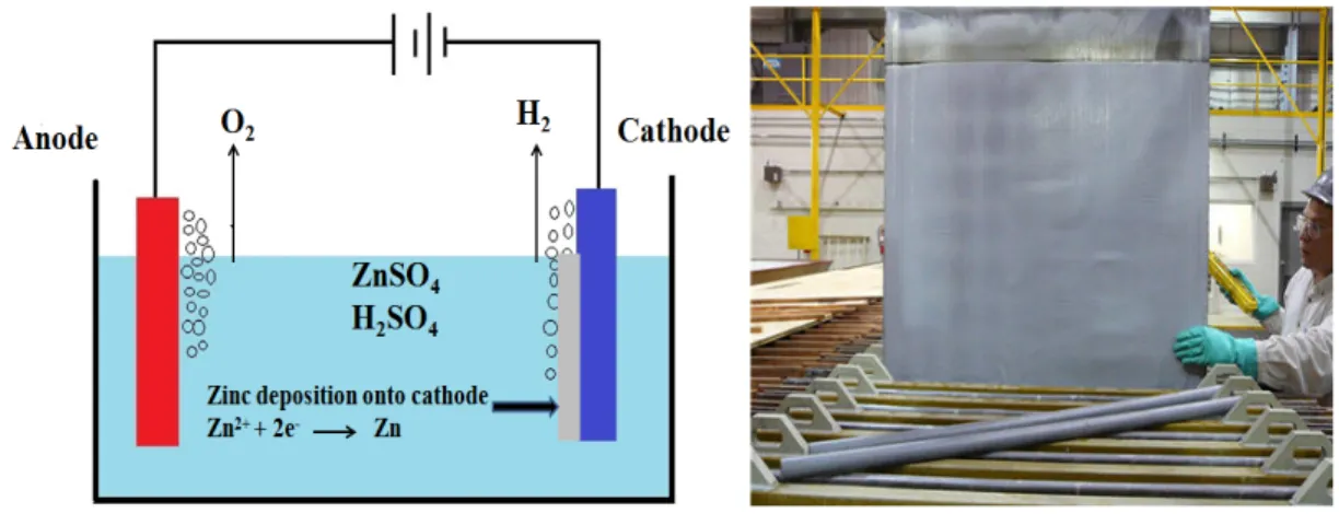
The zinc metal is deposited on the cathode in solid form, while the anodic reaction is the oxygen evolution. The metal deposition rate is always related to the available surface area, maintaining properly working cathodes is important. Two cathode types exist, flat-plate and reticulated cathodes, each with its own advantages. Flat-flat-plate cathodes can be cleaned and reused, and deposited metal is recovered. Reticulated cathodes have a much higher deposition rate compared to flat-plate cathodes. These cathodes are not the best choice as they are not reusable and must be recycled [8]. For zinc electrodeposition, aluminum cathodes are usually used as they proved their high performance. During the electrolysis the deposit is adherent to the aluminum cathodes while, it is separated easily by mechanical methods after the electrodeposition [9].
However, actually one of the main challenges faced by the zinc electrowinning industry is the presence of the metallic impurities in the electrolyte even after several purification steps. These metallic impurities with very small concentrations of ppm or even ppb affect negatively the current efficiency, power consumption, and the purity of the deposited zinc metal [10].
1.2.3. Uses of Zinc
The electrochemical properties of zinc are very important in production as well as applications of zinc. Electrowinning process in zinc refining, electroplating, zinc batteries and zinc coating for corrosion protection of steel are all based on the electrochemical properties [11].
The uses of zinc can be divided into six categories: (a) galvanic coatings for steel, (b) die casting, (c) alloys, (d) zinc chemicals, (e) rolled zinc, and (f) miscellaneous including zinc
oxides and others. As shown in Figure 1.2 the most important application of zinc is its action as protective coatings against corrosion for steel structures due to its relative corrosion resistance in atmospheric and other environments. Approximately, one-half of zinc production is used for this purpose [12-13].
Figure 1.2. The major uses of zinc [13]
Galvanic protection is also called ‘’sacrificial protection’’ as the metal used is sacrificing itself to protect the structure. This type of protection utilizes a galvanic cell consisting of an anode made from more active metal than the structure [12]. So, zinc is the most common
metal used to protect steel due to its position in the electromotive series, [Zn/Zn2+:
-0.76V/SHE] VS [Fe/Fe2+: -0.44V/SHE] as zinc is more active than iron, accordingly it
starts sacrificing itself first before iron.
1.3. Electrodeposition of Alloys as Cathodes in Chlorate Production 1.3.1. Chlorate Production
Chlorate, chlor-alkali, and water electrolysis operations are among the largest consumers of electricity in electrolytic industries. Sodium chlorate (NaClO3) is produced
industrially by an electrochemical process, where chloride ions (Cl-) are oxidized to
chlorine (Cl2) on the anode then dissolved in water forming chlorate ions and hydrogen gas
is evolved on the cathode. The selectivity of main reactions, as well as the energy required by the chlorate process, depends on the electrode materials and surface state also on the electrolyte composition [14]. Galvanizing - 58% Die Casting - 14% Brass / Bronze - 10% Compounds - 9% Rolled Zinc - 6% Miscellaneous - 3%
The electrolytic hydrogen is quite pure and is acceptable for various applications. Normally, hydrogen gas recovery process involves many steps: (a) cooling, (b) boosting, (c) compression, and (d) purification. The obtained hydrogen is used as fuel or as raw
material for the production of HCl [15]. The hydrogen evolution reaction (HER) on
different metalcathodes in acidic or alkaline media is one of the most investigated reactions in the electrochemistry field. The HER was always place of interest due to: (i) hydrogen is an interesting candidate, energy carrier, for fuel cells applications, (ii) it is one of the main reaction products during chlorine production and, (iii) the HER provides the high pure hydrogen gas. This reaction is the main reaction produced in alkaline water electrolysis, hydrogen-based fuel cells, and during some industrial practices such as chlorate cells. Due to the high consumption of energy; reducing the hydrogen evolution overpotential is always one of the challenges and purpose of many studies [15-16].
1.3.2. Cathodes in Chlorate Production
Cathode materials in the first years of chlorate manufacture were copper, nickel and even platinum. Recently, mainly mild steel and in some plants titanium or a Ti-0.2% Pd alloys are used. Chlorate electrolyte containing the oxidizing agents hypochlorite and chlorate is extremely corrosive and oxidises most of those metals when they are not under cathodic protection [17]. Mild steel is one of the most popular used cathodes in chlorate production due to its low cost. However, these cathodes are not the best choice due to the high overpotential values of HER reaching 850-950 mV, depending on the surface roughness also due to low corrosion resistance in the aggressive chlorate electrolyte [18].
Therefore, efforts and attempts are made by many researchers in order to obtain binary and ternary mild steel coated alloys with electrocatalysts exhibiting low hydrogen evolution overpotential as well as improving the corrosion resistance and mechanical properties. Molybdenum and phosphorus are among the different elements that employed to fabricate new cathodes having a positive electrocatalytic behavior towards HER and corrosion resistance. These two elements cannot be electrodeposited directly from the aqueous solutions; therefore, they require another metal to stimulate its co-deposition [19].
1.4. Objectives and Detailed Approaches
The aim of this work is divided into two main objectives:
1.4.1. Effect of Certain Organic Additives on Zinc Electrowinning Process
‐ The main challenge faced by zinc electrowinning industry is the presence of metallic impurities; lead is one of the major impurities as far as lead-based anodes are still used in this process. Pb2+ ions are usually reduced and co-deposited as
elemental lead with zinc metal on the cathode which reduces the purity of the obtained zinc metal. Organic additives proved their good performance in improving this process by reducing the detrimental effect on power consumption, current efficiency and the purity of deposited zinc as well as modifying the surface morphology.
‐ In this study, certain organic additives are chosen from different organic groups: (1) Polyacrylamide [PAM] is one of the well known organic polymers used in industry and has been tested previously as additive in copper electrowinning, showing a good effect in improving morphology of the surface. (2) Tetra-butylammonium bromide [TBABr] is one of the quaternary ammonium salts group which have been examined also as additives. (3) Benzalkonium chloride [BKCl] is a cationic surface-acting agent belonging to the quaternary ammonium salts with aromatic group. (4) Chitin is also selected as it is one of the natural polymer compounds which can be found in crabs, lobsters and shrimps.
‐ Ionic liquid salts are currently used in many chemical and hydrometallurgical applications due to their chemical and physical properties. Ionic liquids are widely used in liquid–liquid extraction and electrodeposition of some metals. Also, they are considered as a medium in the electrodeposition of aluminum on a stainless steel cathode. In this work also, different ionic liquid salts are selected in order to examine their effects on zinc electrowinning process. (5) 1-butyl-3-methylimidazolium chloride [BMIM]Cl, (6) 1-butyl-3-1-butyl-3-methylimidazolium bromide
[BMIM]Br, and (7) 1-Ethyl-3-methylimidazolium methanesulfonate [EMIM]MSO3,
are chosen to be examined as additives in zinc sulphate electrolyte with different concentrations.
‐ The combination between the selected organic additives and antimony as metallic impurities is also considered in this work.
‐ Various electrochemical techniques and other techniques are employed to evaluate the efficiency of these additives in zinc electrodeposition. Galvanostatic polarization, potentiodynamic, cyclic voltammetry are conducted in order to examine the electrochemical activity and the cathodic behavior. Scanning electron microscopy (SEM), X-ray diffraction (XRD), and inductively coupled plasma spectroscopy (ICP) are used as well to determine the surface morphology, crystallographic orientation and lead content in zinc deposit, respectively.
1.4.2. Performing the Electrodeposition of Fe-Mo & Fe-Mo-P Alloys as Cathodes ‐ Chlorate production process is one of the largest consumers of energy in electrolytic
industries. Due to this high consumption of energy; reducing the hydrogen evolution overpotential is always one of the challenges and purposes of many studies. Therefore, improving the cathodic materials exhibiting lower hydrogen evolution overpotential is one of the targets of many studies in order to reduce the power consumption.
‐ In this work, the electrodeposition of different Fe-Mo and Fe-Mo-P coatings on mild steel substrates is carried out in order to study the effect of different phosphorous and molybdenum contents on the HER. The electrocatalytic activities of these cathodes are assessed in simulated conditions of chlorate industry.
‐ Potentiodynamic polarization and electrochemical impedance (EIS) techniques are employed in this work to examine the electrocatalytic activity of the electrodeposited coatings in alkaline solution. Also, (SEM) and (XRD) are used to determine the surface morphology and state, respectively.
CHAPTER 2
Based on the previous reviews and research studies, this chapter is divided into three main parts concerning: (a) additives and impurities in zinc electrowinning, (b) alloyed metals and elements as cathodes used for chlorate production, and (c) recommended electrochemical techniques for evaluation of additives and cathodes during electrolysis. Also, at the end a short summary is given based on the reviewed literature and the objectives of this project.
2.1. Zinc Electrowinning Process
Zinc ores are roasted, dissolved in sulphuric acid and highly purified by zinc dust as explained in chapter 1. Then, metallic zinc is won from the purified zinc sulphate solution by electrolysis using aluminum cathodes and lead-based anodes. Normally, many zinc electrowinning plants operate with current densities of 400-500 A m-2 at temperature of
38±2oC [20].
It is important to understand and determine the electrochemical reactions occur in this electrolysis process in order to measure the potentials and power consumed for electrowinning of zinc. Figure 2.1a shows a simple cell of electrolysis by using aluminum cathode and lead-silver anode in acidic zinc sulphate solution.
The cathodic reactions with standard potentials are:
2 → Eo = -0.763V (2.1)
2 2 → Eo = 0.00V (2.2)
The anodic reactions with standard potentials are:
→ 2 2 Eo = -1.229V (2.3)
The overall reaction is:
As many plants add manganese ions to the sulphate solution due to its remarkable effect in
forming compact layers of MnO2 on the anode to reduce the lead contamination, so,
following reaction cannot be neglected.
2 → 4 2 Eo= -1.208V (2.5)
Approximately, 90% of the cathodic current is consumed to produce zinc metal as reaction (2.1), while, 99% of the anodic current is consumed to produce oxygen gas as reaction (2.3). There are several factors that affect these reactions and their potentials such as: Zn2+
concentration, pH, current density, and temperature [20].Therefore, those variables must be considered in the electrowinning process in any plant.
Figure 2.1. (a) Simple electrolysis cell for zinc (b) Aluminum cathodes deposited by zinc 2.1.1. Lead-Based Anodes
As far as lead anodes are used so, many problems occur due to the weakness and ductility which cause buckling and sagging of the anodes resulting in current distortion in the elctrowinning cell. Also, the corrosion of lead based anodes causes lead contamination of the zinc deposit. When this contamination exceeds the normal level fixed by the plant, maintenance or replacement of the anodes are required [21-22].
Instead, lead alloys containing 0.37 to 1% silver have been used as anodes in zinc electrowinning industry since 1909 [23]. Silver is alloyed with lead anode to reduce the rate of corrosion and improve conductivity of the anode. The addition of silver also reduces the
small amount of silver oxide maybe formed on the surface of the anode along with lead oxides. The poor mechanical property is one of the disadvantages of Pb-Ag anodes accordingly, they are relatively weak and bended quite easily when struck by aluminum cathode sheets when they are removed or inserted to the cell. Therefore, calcium is sometimes added to the alloy by percentage of 0.05 to 0.08% in order to improve the mechanical properties [25].
2.1.2. Corrosion of Lead-Based Anodes
Lead metal can be dissolved by oxidizing acidic solutions with the formation of
divalent plumbous ions Pb2+. Further oxidation can result in conversion of divalent
plumbous ions into brown quadrivalent lead dioxide PbO2. In the absence of passivating
substances such as carbonates, and oxidizing action can cause lead to corrode, except at
high electrode potentials where PbO2 is stable [26].
Figure 2.2. Potential-pH diagram obtained according to the ionic activities in an actual anodic film for the Pb-H2O-H2SO4 system at 25oC (potential vs. SHE) [27]
Guo Y. [27] determined the potential-pH relation of lead in sulphuric acid as Figure 2.2.
This diagram includes the basic lead sulphates PbO.PbSO4, 3PbO.PbSO4.H2O and the
tetragonal oxide, PbO (PbOt). When a lead electrode is immersed in sulphuric acid solution
and polarized anodically to potentials in the area of stability of PbO2.
It has also been observed by X-ray diffraction (XRD) analysis that two forms of PbO2 are
found with rhombic (α-form) being stable at lower potentials than the tetragonal (β-form).
α-PbO2 they found that they show more dense deposits, composed of large and closely
packed crystals. On the other hand, β-PbO2 deposits are less compact being composed of
poorly bonded, fine, needle shaped crystals [28]. However, the problem of lead
contamination of zinc deposit is still the solution by lead ions is the most critical problem in zinc electrowinning.
2.1.3. Oxygen Overpotential of Lead-Based Anodes
Two main reactions occur on the anode which are; the evolution of oxygen gas O2
and the oxidation of PbSO4 to PbO2[27]. The oxidation of water to oxygen is theoretically
possible at 1.23 V according to reaction (2.3), but production of oxygen is only observed at potentials more positive than the equilibrium potential for the PbO2/PbSO4. Therefore, the
oxidation of lead sulphate to lead dioxide and the evolution of oxygen gas require overpotentials.
During the electrowinning, lead alloys are immersed in the zinc electrolyte, the reaction (2.6) takes place on the fresh anode surface at first;
→ 2 E= -0.356 V/SHE (2.6)
The anode surface is covered with time by non-conducting layer of PbSO4. The anodic
current density and the potential on that part of the anode surface of non-covering with
PbSO4 increase. The following reaction is expected on the Pb surface at atmospheric
temperature:
This reaction takes place instead of reaction (2.6), thus, a well conducting PbO2 occurs
instead of PbSO4, so the current density and the anodic potential decrease. The reaction of
the oxygen evolution starts on the layer of PbO2 and sulphuric acid in the renewed
electrolyte. After the anodic film formation, ≈ 99.20% of the electricity goes to the oxygen evolution, ≈ 0.67% for formation of PbO2 and ≈ 0.13% for the other reactions [29].
The overpotential of oxygen can be reduced if a good lead anode is used, or alloyed with another metal. As discussed previously that silver is the major metal could be alloyed with lead at certain limit due to its high cost to reduce oxygen overpotential. It has shown also that anodic potential of Pb and Pb-Ag anodes becomes more positive with the increase of electrolyte acidity. The overpotential of Pb-Ag (1% Ag) anodes is 80-120 mV less than that of pure Pb [30]. Table 2.1 illustrates the relation of electrode potential by changing different alloys of anode at different current densities.
Table 2.1.Electrode potential (V/SCE) vs. current density (A m-2) of anodes from lead and
its alloys in 1.8 M H2SO4 at 30oC[30]
Current density (A m-2)
Electrode potential vs. V/SCE
Pb Pb-Sn 1%- Ca 0.07% Pb-Ag 0.37% Ca 0.12% - Ti 0.99% Pb-Ag 0.97% Sn 0.63% Pb-Ag 0.76% Pb-Ag 0.9% Ca 0.04% 250 1.915 1.925 1.880 1.850 1.835 1.810 500 1.940 1.955 1.915 1.885 1.870 1.850 1000 1.975 1.980 1.945 1.925 1.915 1.885
2.1.4. Role of Manganese Ions in the Electrolyte
Usually, manganese ions are added to electrolyte to reduce lead contamination as mentioned previously. Mn2+ ions are active electrochemically at lead or lead alloyed anodes
and the manganese oxide may be formed after the formation of PbO2 on the anode before
extensive evolution of oxygen occurs. It has been shown that the electrochemical deposition of manganese on the anode may act favorably to minimize disintegration of the anode scale by decreasing the amount of lead dioxide PbO2 formed on the anode [31].
Usually, manganese ions are added continuously to the industrial electrolyte in the form of MnSO4, and accordingly the followings reactions are expected on the anode [30]:
2 → (2.8)
4 → 6 5 (2.9)
2 → 3 (2.10)
3 2 2 → 5 3 (2.11)
The lead anode is protected from corrosion by MnO2 and PbO2 layers, since the well
adherent oxide film of MnO2 increases the thickness and oxide layer PbO2-MnO2 which
acts as barrier on the anode surface. The presence of Mn2+ ions affects slightly the anodic
potential since the potential decreases as a result of depolarization effect during the oxidation of Mn2+ on the anode. The potential decreases also as a result of the formation of
a protective layer of manganese oxides. Moreover, the presence of Cl- ions in the
electrolyte leads to a considerable decrease of the anodic potential for lead-based anodes. Also, the increase of temperature results in a remarkable decrease of the anodic potential in the presence of Cl- ions [30,32]. Figure 2.3 shows the lead-based anode before and after 5
hours of electrolysis as the corrosion of the anode is very remarkable with formed MnO2
layers.
However, studies proved that Mn2+ ions have also an effect on the cathodic reactions at
high concentrations. Zhang and Hua [33] revealed that adding Mn2+ ions in the
concentration range of 1-10 g dm-3 has no significant effect on the current efficiency (CE),
while a decrease in CE of more than 35% was happened at addition of high concentration of 50 g dm-3. This decrease in CE was due to the strong depolarizing effect of MnO4- ions
and other oxidized products of manganese on hydrogen evolution reaction. The addition of Mn2+ ions was also observed to change the surface morphology and deposit quality of the
Figure 2.3. Lead-based anode; (a) Before electrolysis and (b) After 5 hours of electrolysis 2.1.5. Surface Structure and Crystallographic Orientation
Almost all electroplated or electrodeposited metals are crystalline, which means that the atoms are arranged in a regular three dimensional pattern called ‘’Lattice’’. The most known lattices are: (i) face centered cubic (FCC), (ii) body centered cubic (BCC), and (iii) hexagonal close packed (HCP) (Figure 2.4). Normally, Zn atoms are arranged in lattice
type hexagonal close packed (HCP) [34]. The crystal structure resulting from an
electrodeposition process is strongly dependent on the relative rate of formation of crystal nuclei and growth of existing crystals. Finer-grained deposits are the result of conditions that favourite crystal nuclei formation, while larger crystals are obtained in those cases that favourite growth of existing crystals. Generally, a decreasing crystal size is the result of factors which increase the cathodic polarization such as: increasing current density, different electrolytes, and addition of colloids or additives [35].
Texture, which is preferred distribution of grains (individual crystallites) having a particular crystallographic orientation with respect to a fixed reference frame, is an important structural parameters for bulk materials and coatings. It is important to be able to specify certain planes in crystal lattices. Miller indices signify a single plane or set of parallel planes which are always presented in parentheses such as (100).
Figure 2.4. Zinc deposit shows HCP Lattice among the three most important lattices
Electrochemical parameters appear to be the only controlling factor. For example, texture mainly depends on the cathodic potential and pH of the solution for a given electrolyte composition, this also applies to current density if temperature is constant. It has been revealed that electrodeposits have the (111) direction normal to the surface for BCC crystal structures and the (110) direction for FCC substrates, independent of substrate orientation. With hexagonal closed packed HCP metals such as zinc, the (101) direction is predominant
[36].
2.1.6. Metallic Impurities in Zinc Electrowinning
The presence of metallic impurities in zinc sulphate electrolyte is a critical problem for zinc electrowinning industry. Low concentrations of metallic impurities influence negatively the zinc deposition on the cathode; leading to a decrease in current efficiency, a change in deposit morphology as well as an increase in cell voltage [37-38]. Actually, the reduction of hydrogen ions in solution is affected in the presence of the impurities. Certain impurities, e.g. Ge and Sb are hybrid formers may facilitate the hydrogen evolution reaction HER, other impurities such as Ni and Co, more noble than zinc, cause re-dissolution of the zinc deposit (low current efficiency) [39].
There have been many studies over the past decades dealing with the harmful effect of impurities in zinc electrowinning. While, most of electrolytic zinc plants follow the same general procedures in order to keep the optimal operating conditions which have usually been arrived by experience and depend on the type of zinc ore treated and its impurity content [37].
2.1.6.1. Effect of Lead Impurity on Zinc Deposition
As mentioned previously that lead impurity is one of the challenges in zinc electrowinning industry so, some studies were done to investigate the effect of lead ions in the solution. Mackinnon et al. [40] conducted several investigations of the influence of lead in an industrial zinc solution (55 g dm-3 Zn2+ + 150 g dm-3 H2SO4). They found that the
effect of lead (6 mg dm-3 at 35oC) on current efficiency was current density dependent,
producing an increase of ~0.7% at 400 A m-2 and a reduction of ~1.5% at 800 A m-2.
Increasing amounts of lead in the zinc deposits progressively changed the preferred crystalline orientation from (112) to (101) to (100) to finally a poorly (002) crystalline structure. The same results trend was also proved by Ault and Frazer [37]. The lead content of the zinc deposits was dependent on the solution concentration of lead, the form in which lead was added, the current density as well as presence of Sb and glue. Table 2.2 shows the variation of current efficiency and preferred orientation of deposits in different concentrations of lead. Also, Figure 2.5 shows the deposit morphology with different additions of lead [37,40].
Table 2.2. Variation of current efficiency and preferred crystalline orientation of zinc deposit at different concentrations of lead at 400 A m-2 and 35oC for zinc electrolyte of 55 g
dm-3 Zn2+ + 150 g dm-3 H2SO4[37]
Initial Pb
(mg dm-3) (mg dmFinal Pb -3) Pb removed (%) Change in CE (%) orientation Preferred
0 0.01 - - Random 1.0 0.25 75 0.3 (102) (103) (104) 2.0 0.6 70 0.8 (004) (002) 3.0 0.9 70 0.9 (004) (002) 4.0 1.4 65 1.0 (004) (002) 5.0 1.7 66 1.1 (004) (002)
Figure 2.5. SEM photomicrographs (X 385) showing the effect of current density on the morphology of zinc deposits from addition-free electrolyte using unconditioned Pb-Ag anodes. (a) 215 A m-2, 60 min, 0.125% Pb; (b) 323 A m-2. 60 min, 0.076% Pb; (c) 430 A m -2, 60 min, 0.04% Pb; (d) 538 A m-2, 60 min, 0.021% Pb; (e) 1076 A m-2, 30 min, 0.019%
Pb; (f) 2152 A m-2, 15 min, 0.011% Pb [40]
2.1.6.2. Effect of Antimony Impurity on Zinc Deposition
Antimony has been known as one of the most toxic solution impurities with respect to current efficiency (CE). Ault and Frazer [37]and Lafront et al.[41] studied the effect of different concentrations of Sb3+ of 0.0055-19 mg dm-3 in high purity-solutions on CE and
morphology; they found that it has a dramatic effect on CE with decrease of ~5.2 to 62.3%. With such small concentrations of antimony present in the solution, this decrease can be assumed due to the catalytic production of hydrogen which inhibits the reduction of Zn2+.
The variation of current efficiencies and preferred orientation of deposit with addition of antimony are shown in Table 2.3. Also, antimony had a dramatic grain-refining effect on zinc deposit, reducing platelet size even at low concentrations of 0.02 - 0.04 mg dm-3
Table 2.3. Variation of current efficiency and preferred crystalline orientation of zinc deposit at different concentrations of antimony at 400 A m-2 and 35oC for zinc electrolyte
of 55 g dm-3 Zn2+ + 150 g dm-3 H2SO4[37]
Initial Sb
(mg dm-3) (mg dmFinal Sb -3) Sb removed (%) Change in CE (%) orientation Crystal
0 4.0 - - Random 4.0 4.0 0 -5.2 (112) (212) 7.0 5.0 29 -10.0 (112) (211) 10.0 9.0 10 -23.6 (112) (101) 14.0 10.0 29 -52.4 (104) (101) 19.0 13.0 32 -62.3 (004) (103)
Figure 2.6. SE micrographs showing the morphology of 6h zinc deposits electrowon at 500 A m-2 and 38oC from electrolytes containing; (a) and (b) 0.02, (c) and (d) 0.04 mg dm-3 Sb [42]
Although antimony has negative effect on zinc deposit, it showed very good effect when combined with some organic additives such as glue and gelatin.
2.1.6.3. Effect of Copper, Nickel and Cobalt Impurities on Zinc Deposition
Although copper readily removed from zinc electrolyte by zinc dust cementation purification, it can re-enter the electrolyte via corrosion of the bus bars. It is known also that copper co-deposit with zinc leading to a reduction of metal quality at certain concentrations. Ault and Frazer [37] also Mackinnon [43] studied the effect of Cu on current efficiency and crystal orientation at different concentrations and different current densities (Table 2.4).
It is shown that content of electrodeposited zinc increased with increasing copper concentration in the electrolyte and with decreasing current density. Although copper deposited with zinc, it did not result in a dramatic decrease in the current efficiency but co-deposited copper reduced the grain size of the zinc deposits [43].
Table 2.4. Effect of copper on current efficiency and crystal orientation of zinc deposit at different concentrations and different current densities for electrolysis in 55 g dm-3 Zn2+,
150 g dm-3 H
2SO4 at 35oC [43]
Current density
(A m-2) (mg dmCopper -3) (%) CE Copper (%) Cathode Orientation Crystal
430 0 93.6 - (112)(103)(102) 5 93.0 0.025 (112)(110) 10 95.3 0.060 (112)(110) 20 95.1 0.095 (112) 30 92.3 0.157 (114)(112) 50 92.5 0.254 (002)(101) 323 0 96.0 - (112) 10 94.0 0.041 (112) 20 92.4 0.129 (101)(103) 30 94.8 0.240 (002)(101) 50 93.0 0.399 (002) 215 0 94.3 - (112) 10 92.1 0.065 (101)(102)(103) 20 93.9 0.161 (101)(002)(103) 30 90.7 0.232 (101)(002) 50 88.5 0.393 (101)
Nickel is one of the most injurious impurities in the electrolytes. During the electrowinning of zinc from sulphate electrolytes in the presence of nickel, a re-dissolution process of the deposited zinc takes place. Nickel co-deposits with zinc and forms numerous galvanic micro-batteries. Hydrogen evolves on the nickel zone and surrounding zinc re-dissolves, causing spongy and dark deposits [44]. After many formation and dissolution cycles of the zinc deposits, the frequency of the cycle increases, since the cathode is polluted gradually by nickel until zinc deposition can no longer occur. Ault and Frazer [37], Stefanov and Ivanov [45], and Morrison et al. [46]studied the effect of Ni impurity on current efficiency and deposit structure during zinc electrowinning (Table 2.5). Briefly, the more noble co-deposited metals with Zn enhance hydrogen evolution in acidic medium and their effect is expected to be in the following order: Ni, Co, and then Cu.
Table 2.5. Variation of current efficiency and preferred crystalline orientation of zinc deposit at different concentrations of nickel at 400 A m-2 and 35oC for zinc electrolyte of
55 g dm-3 Zn2+ + 150 g dm-3 H
2SO4[37]
Initial Ni
(mg dm-3) Change in CE (%) Orientation Crystal
0 - Random 0.25 -0.1 (114) (102) 0.5 -0.1 (114) (102) 1.0 -0.2 (114) (102) 1.5 -0.1 (211) (105) 2.0 -0.2 (114) (102) 5.0 -0.3 (204) (102)
The CE declined very slowly, with increasing nickel concentration, with most of the
decrease occurring in the 0-1 mg dm-3 range. The crystal orientation changed from a
relatively random pattern with (102), (104), (114), (204) as major plans, to an orientation dominated by the (114), (102), (204), (203) plans, when the nickel concentration was in the range 0.25-2 mg dm-3. At 5 mg dm-3 Ni the (114) plane was replaced by the (204) plane.
Cobalt combined with nickel is difficult to be removed from the electrolyte, can have disastrous effect on zinc electrowinning under certain conditions [47]. Maja and Spineli
zinc electrowinning. The term “induction time or period” is used in zinc electrowinning. During this induction time, which coincides with the beginning of zinc electrodeposition, the zinc deposits are uniform and adhere firmly to the cathode. The typical current efficiency is 93‐95%. Following this induction time, zinc re‐dissolution occurs with hydrogen evolution. After the zinc is completely dissolved, deposition restarts. The induction time depends on several factors such as temperature, cathodic current density, and the concentrations of sulphuric acid, zinc and impurities [50-51].It has shown that an induction period more than one hour exists before cobalt and nickel begin to have an effect on CE and zinc deposit. After the induction period CE decreases rapidly with time. The length of induction period decreases with increasing temperature, increasing acid concentration and with decreasing current density [49].
2.1.7. Additives in Zinc Electrowinning
The presence of high concentrations of impurities in the industrial electrolytes decrease the induction period associated with zinc electrowinning process resulting in deterioration of zinc deposit quality and in decrease the current efficiency [51]. High quality and high current efficiency of zinc deposit are always obtained from pure electrolytes. However, various electrolyte purification steps are nonviable economically. Accordingly, an alternative method to reduce the detrimental effect of metallic impurities is to use suitable organic additives [52]. These additives may be classified into non-ionic, anionic and cationic types. Most of used additives are organic materials with high molecular weight which could be adsorbed on the cathode and act as a diaphragm (hydrogen inhibitor and crystal growth modifier). In industrial zinc deposition the most commonly used additives are the naturally occurring, gums, gelatins or glues which in acidic solutions are cationic [53].
2.1.7.1. Effect of Glue
Animal glues are most known additives in the zinc electrowinning industry. Such additives are often added to the electrolyte at low concentrations in order to have smooth
and compact zinc deposit. Although glues have beneficial leveling effect on zinc deposit but when increasing the addition alone to the purified electrolyte usually result in a decrease in the current efficiency of zinc deposit. Also, addition of glues alone to the pure electrolyte leads to cathodic overpotential this is due to the re-arrangement of
crystallographic orientations which consumes over voltage [39]. Moreover, glues also
interact in a beneficial way with certain impurities in the electrolyte; one of those famous impurities is antimony. Addition of glue to an electrolyte contains low concentrations of Sb
(≤ 0.02 mg dm-3) optimizes zinc deposition CE and modify the zinc deposit morphology
and preferred crystallographic orientation. In spite of the detrimental effect of Sb on CE, a small concentration of antimony is usually added to the electrolyte to reduce zinc deposit adherence to the aluminum cathode and because its beneficial interaction with glue [37]. Glue in presence of antimony has also a significant effect on the zinc deposition overpotential [54]. The addition of glue alone increases the overpotential; that is polarizes zinc deposition while increasing the concentrations of antimony decrease the overpotential due to the high hydrogen evolution. Accordingly, balanced additions of glue and antimony produce zinc deposit potential or (nucleation overpotential) that results in an optimum
values for the CE with uniform deposit [22,55]. The term ‘’Nucleation Potential’’
corresponds to the commencement of the reduction of Zn2+ at the cathode. This potential
can be easily determined by cyclic voltammetry technique. While, the potential difference between the crossover point and the point where the Zn2+ ions are started to be reduced on
the cathode is known as nucleation overpotential (NOP). NOP is used to elucidate the extent of polarization of a cathode, and high NOP values indicate strong polarization. It is a convenient parameter to show the effects of various additives on zinc electrowinning. The number of nuclei can be calculated by the following equation:
.
ɳ
Where; α and b are constants, ɳ is the nucleation overpotential. It indicates that the higher nucleation overpotential, the much more fine-grained zinc deposits can be obtained with good crystallographic orientation[56].
It was found that, adding 0.02 mg dm-3 of Sb3+ ions to standard zinc electrolyte reduced CE
from 91% to 86.7% while adding 5 mg dm-3 of glue to this electrolyte in presence of same
quantity of antimony succeeded to increase CE from 86.7% to 92.4%. Presence of antimony reduced NOP by 75 mV which indicates non-smooth and very small grain size as well as distortion in crystallographic orientation while addition of 5 mg dm-3 of glue
restored the normal values of NOP and formed medium grain sizes [42].
2.1.7.2. Effect of Natural Products and Surfactants
Natural products and surfactants were always the concern of many studies as additives in zinc electrowinning. Saponins, Licorice, Tennafroth 250, and Dowfroth 250 were studied as additives by different concentrations (0, 5, 10, and 15 ppm) also their effects on acid mist suppression have been reported [57].
‐ Saponins: are found in various plants, they are amphipathic glycosides grouped phenomenologically by the soap-like foaming.
‐ Licorice: is the root of Glycyrrhiza glabra from which a sweet flavour can be extracted. The scent of licorice root comes from a complex and variable combination of compounds, of which anethole is up to 3% of total volatiles. Much of the sweetness in liquorice comes from glycyrrhizin, which has a sweet taste, 30– 50 times the sweetness of sugar.
‐ Tennafroth 250 and Dowfroth 250: are products of Dow Company which used as foam sealants.
Studies reported that, none of the additives succeeded to increase the CE%. While, Tennafroth 250 and Dowfroth 250 appeared to achieve high acid mist suppression efficiency (66% and 62% respectively). The high suppression efficiency with low power consumption for both additives was supported by surface tension results (67.6 and 67.9 mN/m respectively) and polarization behavior obtained by cyclic voltammetry (NOP at 66 and 48 mV [57].
Sodium lignin sulphonate had been studied by Alfantazi and Dreisinger [58]. The addition of sodium lignin sulphonate up to 10 ppm had no negative effect on zinc electrowinning
process, nor on the quality of the zinc deposits. CE% maintained constant with addition of this surfactant.
Also, the extract of horse-chestnut tree (HCE) was tested as an additive in zinc electrowinning. The additives increased the cathodic polarization and promoted leveling. HCE had a beneficial influence on the zinc deposit quality, being a good leveling agent by increasing the nucleation overpotential NOP and the deposition rate of zinc on the cathode
[59].
However, studies proved that gelatin acts more or less as glue in presence of small traces of
antimony in the zinc electrolyte. Small concentrations of antinomy (0.0055 mg dm-3)
reduced the CE by ≈7%, with depolarization by ≈40 mV, while addition 1 mg dm-3 of
gelatin to this electrolyte restored back the normal values of current efficiencies [41].
2.1.7.3. Effect of Synthetic Polymers
The behavior of zinc electrodeposition and Zn deposit morphology were studied in electrolytes containing polymer additives such as polyethylene glycol (PEG) [60]. PEG
with molecular weight of 1.54x10³ was added to the electrolyte with different
concentrations (0, 0.001, 0.01, 0.1, and 1 mg dm-3). Results showed that, PEG acts as a
polarizer to shift the deposition potential of zinc in a less noble direction. It was found that, increasing the concentration of additive shifted the cathodic potential to more negative values starting from ~-0.87 V at zero addition to ~-0.93 V at 1 mg of PEG. Another series of experiment have been done in order to observe the effect of molecular weight of polymer on the cathodic potential and polarization resistance. As the molecular weight of PEG increases, the overpotential and the polarization resistance for Zn deposition first increased, but then decreased when the molecular weight exceeded 1x10⁴.
When the molecular weight of the polymer is less than 1x10⁴, almost all the oxygen
radicals are utilized for adsorption to inhibit zinc deposition effectively. So, the electrolytic solution contains a smaller number of longer chains as the molecular weight increases. As a result, the Zn deposition potential is shifted in a less noble direction and the polarization
resistance for Zn deposition increases. It can be concluded that, the degree of polarization depends on the molecular weight of the additive.
The electrodeposits obtained from additive-free solution are composed of hexagonal platelets with medium grain size, while the deposits obtained from solution containing PEG are found to have grain size smaller than that obtained from free-addition electrolyte [60].
2.1.7.4. Effect of Quaternary Ammonium Salts
Quaternary ammonium salts are characterized by having positively charged nitrogen (cation) covalently bonded to four alkyl group substituents (non-aromatic) (Fig. 2.7a) and/or benzyl substituents (aromatic) (Fig. 2.7b). R = CnH2n+1, where n=8 to 18, with
mixture of carbon chain lengths, predominantly 12, 14 or 16. Quaternary ammonium salts
are known with their stability under neutral or acidic conditions up to 150oC, but
decomposition can occur with the quaternary ion acting as an alkylating agent in its reaction with anion [61].
Figure 2.7. Quaternary ammonium salts; (a) Non-aromatic, (b) Aromatic
The effect of some quaternary ammonium salts represented in cetyltrimethyl ammonium bromide (CTABr) and tetrabutyl ammonium bromide (TBABr) on zinc electrowinning
have been investigated [62]. Results indicated that CTABr has approximately similar
properties to glue the commonly used additive in industry. CTABr has been found to have the same polarization behavior, crystallographic orientation and surface morphology like glue while TBABr has less useful properties. This could be explained due to the higher molecular weight. Addition of small concentrations of CTABr (1 mg dm-3) to the standard
![Figure 1.1. Typical roast-leach-electrowinning processes for zinc [7]](https://thumb-eu.123doks.com/thumbv2/123doknet/6464306.172184/20.918.150.727.441.852/figure-typical-roast-leach-electrowinning-processes-zinc.webp)
![Table 2.1. Electrode potential (V/SCE) vs. current density (A m -2 ) of anodes from lead and its alloys in 1.8 M H 2 SO 4 at 30 o C [30]](https://thumb-eu.123doks.com/thumbv2/123doknet/6464306.172184/31.918.136.787.571.730/table-electrode-potential-sce-current-density-anodes-alloys.webp)
![Table 2.2. Variation of current efficiency and preferred crystalline orientation of zinc deposit at different concentrations of lead at 400 A m -2 and 35 o C for zinc electrolyte of 55 g dm -3 Zn 2+ + 150 g dm -3 H 2 SO 4 [37] Initial Pb (mg dm -3](https://thumb-eu.123doks.com/thumbv2/123doknet/6464306.172184/35.918.177.745.677.873/variation-efficiency-preferred-crystalline-orientation-different-concentrations-electrolyte.webp)
![Figure 2.6. SE micrographs showing the morphology of 6h zinc deposits electrowon at 500 A m -2 and 38 o C from electrolytes containing; (a) and (b) 0.02, (c) and (d) 0.04 mg dm -3 Sb [42]](https://thumb-eu.123doks.com/thumbv2/123doknet/6464306.172184/37.918.233.688.432.872/figure-micrographs-showing-morphology-deposits-electrowon-electrolytes-containing.webp)
![Table 2.5. Variation of current efficiency and preferred crystalline orientation of zinc deposit at different concentrations of nickel at 400 A m -2 and 35 o C for zinc electrolyte of 55 g dm -3 Zn 2+ + 150 g dm -3 H 2 SO 4 [37] Initial Ni (mg d](https://thumb-eu.123doks.com/thumbv2/123doknet/6464306.172184/39.918.190.732.547.759/variation-efficiency-preferred-crystalline-orientation-different-concentrations-electrolyte.webp)
![Table 2.7. Effect of Sb 3+ on current efficiency in absence and in presence of [BMIM]HSO 4](https://thumb-eu.123doks.com/thumbv2/123doknet/6464306.172184/48.918.164.753.168.426/table-effect-current-efficiency-absence-presence-bmim-hso.webp)
![Figure 2.10. Scanning micrographs of developed cathodes [86]](https://thumb-eu.123doks.com/thumbv2/123doknet/6464306.172184/53.918.213.714.111.315/figure-scanning-micrographs-developed-cathodes.webp)
