HAL Id: hal-00830910
https://hal-mines-paristech.archives-ouvertes.fr/hal-00830910
Submitted on 6 Jun 2013
HAL is a multi-disciplinary open access
archive for the deposit and dissemination of
sci-entific research documents, whether they are
pub-lished or not. The documents may come from
teaching and research institutions in France or
abroad, or from public or private research centers.
L’archive ouverte pluridisciplinaire HAL, est
destinée au dépôt et à la diffusion de documents
scientifiques de niveau recherche, publiés ou non,
émanant des établissements d’enseignement et de
recherche français ou étrangers, des laboratoires
publics ou privés.
A System On Chip Dedicated To Pipeline Neighborhood
Processing For Mathematical Morphology
Christophe Clienti, Serge Beucher, Michel Bilodeau
To cite this version:
Christophe Clienti, Serge Beucher, Michel Bilodeau. A System On Chip Dedicated To Pipeline
Neigh-borhood Processing For Mathematical Morphology. 16th European Signal Processing Conference
(EUSIPCO 2008), Aug 2008, Lausanne, Switzerland. 5 p. �hal-00830910�
A SYSTEM ON CHIP DEDICATED TO PIPELINE NEIGHBORHOOD PROCESSING
FOR MATHEMATICAL MORPHOLOGY
Christophe Clienti, Serge Beucher, Michel Bilodeau
Center of Mathematical Morphology, ENSMP 35 Rue Saint Honor´e, 77300, Fontainebleau, Francephone: + (33) 1 64 69 47 06, fax: + (33) 1 64 69 47 07, email: [email protected] http://cmm.ensmp.fr
ABSTRACT
This paper describes a system on chip to compute neighbor-hood operations for image processing algorithms. The sys-tem is based on General Purpose Processor in charge of algo-rithms scheduling in a deep pipeline named SPoC. The latter is an dedicated architecture to compute neighborhood pro-cessing operations thanks to data stream vectorized proces-sors connected each others with a reconfigurable data path. Two applications, a motion detection algorithm and a licence plate extraction are presented to show performances in terms of speed, embeddability and re-usability of the SoC. Compar-isons with many architectures such as digital signal proces-sors, workstations or embedded general purpose processors are made to benchmark the platform and prove the originality and the strength of our solution.
1. INTRODUCTION
Since more than 40 years, the use of Mathematical Morphol-ogy for image processing is constantly growing in many do-mains such as medical imaging, computer vision, multimedia application or security [1], [2].
Faced with increasing demand for embedded systems dedicated to efficient image processing, traditional systems are not sufficient to achieve robust real-time applications. Moreover applications are more and more sophisticated and dedicated architectures for image processing are often only specialized in peculiar parts of an application. we can cite many architectures only optimized for some basic operations [3], [4].
Digital signal processors and SIMD processors are not always well suited to very large numbers of calculations re-quired by some sequential stages of an application. Moreover applications require a lot of memory due to increasing reso-lution of sensor and due to algorithms increasing complexity. Processors can not be fast enough and cache misses may oc-curs [5]. Wide VLIW or Systolic architecture composed by hundreds of simples processing elements are an alternative to compute algorithm rapidly, however programming model could be often very complicated [6], [7].
Using a neighborhood operators pipeline, where each stage could map an application part, is a possibility to sim-plify processing and improve performance. In the past, such pipelines were built off-chip with many circuits arranged to-gether to target performance needed [8]. Mathematical Mor-phology is really well suited to this kind of architecture be-cause it is based on simple operations which can fit into one or more stages of a pipeline. Today we have the opportu-nity to create reconfigurable architecture with many on-chip
neighborhood operators interfaced with generic purpose pro-cessor to schedule processing.
The first part of the paper is dedicated to a short re-minder about Mathematical Morphology. In the second part, the platform architecture is presented and emphasis is being placed on vectorized neighborhood processor able to extract multiples sub-window at a time. In the third part, two appli-cations, a video survey motion detection and a licence plate extraction, are described and a benchmark is done between our SoC and different platforms. Finally, the last part is ded-icated to improvements and future works.
2. MATHEMATICAL MORPHOLOGY REMINDER Mathematical Morphology was created in late 60’s by G. Matheron and J. Serra. The two morphological basic oper-ations are dilation and erosion, from which, all others opera-tions can be composed.
An Erosion of an function f by a flat structuring element
B is defined as follow:
[εB( f )](x) = min
b∈B( f (x + b))
The dual operator is the dilation: [δB( f )](x) = max
b∈B( f (x + b))
A structuring element is a neighborhood window, where for each pixel of the image a set of neighborhood is considered. Those primitive are considered as basic tools achieving a lot of more complex operations :
• gradient, laplacian • openning, closing • geodesic transformations • distance, quasi-distance
• skeleton (using Hit or Miss operators) • watershed
• ...
We invite the interested reader to read the Morphological Image Analysis book [2] for an exhaustive introduction to Mathematical Morphology.
The challenge is to build the best optimized architecture to compute rapidly erosion/dilation and to schedule them ef-ficiently.
3. PLATFORM DESCRIPTION
The aim of the designed circuit is to compute Mathemati-cal Morphology algorithms in the framework of embeddable
systems. It is able to acquire images from a source, compute them, and transmit results in real-time constraint evaluated at 30 frames per second. The functional view of the SoC is presented in figure 1.
Figure 1:System on Chip for Image Processing With Mathematical Mor-phology
3.1 Chip structure
The circuit is composed by a simple General Purpose Proces-sor (GPP) which is devoted to control algorithm scheduling and communication in and out of the circuit. If necessary, the GPP can access to image pixels located in the DDR-RAM. This must be sporadic because of important memory latency when cache misses occurs. GPP is a simple 32 bits RISC pro-cessor operating at a low frequency and may run an Operat-ing System to manage network communications. Image pro-cessing are deported in a dedicated part of the circuit named SPoC (Several neighborhood Processors On Chip). In or-der to feed the pipeline with pixels throw FIFOs, a standard DMA is used to optimize memory transfer from and to the DDR-RAM.
The input video system supports standard video inputs as PAL or NTSC, converted into numerical trams with an exter-nal ADC. The video input logic inside the SoC is used to de-code frames and to take control of the SoC bus to send pixels directly in DDR-RAM. Optionals parts are the framebuffer and the video output which represents a basic graphics sys-tem mainly used to display some image processing results.
SPoC is optimized to minimize image memory trans-fers between each application stage. The pipeline struc-ture allows to process some operations with only one image load/store and it exploits temporal and spatial parallelism to speed up computations. SPoC processing configuration is built with a list of basic operations parameters to be executed such as dilation or erosion, and with a data path parametriza-tion. All those parameters must be stored in configuration registers before starting a process. Border side effects are automatically managed, and only tasks devoted to the GPP are SPoC registers programming and DMA configuration.
Once the pipeline is configured, images pixels are sent to input FIFOs and the process could start. If two images must be sent to the accelerator, the process will start only when pixels will be available in each FIFO. After a latency equal to some lines of an image, depending of the pipeline depth, pixels result are produced and stored in output FIFO at each clock cycle. The GPP must program the DMA to store pixels
progressive results in main SoC memory. 3.2 SPoC structure
SPoC is composed by many neighborhood processors, called PoC, associated in a parallel and in a serial way throw a re-configurable data path and a programmable ALU units, as shown in figure 2. One PoC is able to compute erosion, di-latation, gradient and optionally median filter and convolu-tion with kernel up to 3 × 3.
Figure 2:SPoC internal overview
The pipeline structure is really well suited to Mathemati-cal Morphology, and the former is fully used most of the time by each application stages. Moreover SPoC is a MIMD ar-chitecture and can process one image in both parallel PoC with the same instruction or process two different images with different operations. Multiplexers in the pipeline allow to use all PoC in the circuit in a serial way. This option is very interesting when we compute alternate sequential filters with big structuring element size.
The ALU unit manages results from parallel PoC, and also reconfigure data paths before a process start. This part is important to compute geodesic operation, distance trans-formation or any complex transtrans-formation. The ALU unit embedded also a Constant Pixel Register (CPR) to compute operations on each pixels with a constant value instead of an image. The figure 3 represents the ALU functional view.
Figure 3:ALU functional overview
The ALU unit allows to compute addition, subtraction, saturated addition, saturated subtraction, absolute value of a subtraction, minimum, maximum on both images input or between an input and CPR. The NOP instruction is decom-posed in two NOP instructions in order to choose which input must be directly copied to the output. Compare operations have been introduced to do conditional move or threshold, and many combinations between inputs and CPR are avail-able. For example, we can compare each pixels of two im-ages and replace true values by the CPR when a test is sat-isfied. We can also test if a pixel is superior to CPR and set the output to the max value authorized by the pixel bus width (0xFF for 8-bit pixels).
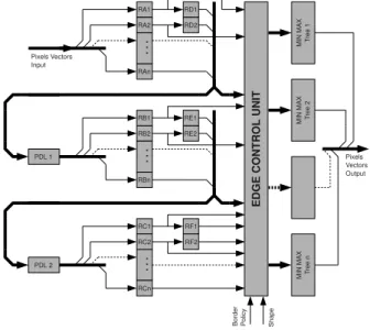
PoC implements a parallel neighborhood extractions to speedup computation time as shown in figure 4. At each
clock cycle, PoC extract N successive neighborhoods de-pending of the pixel vector of size N. The figure 5 shows a simplified view of the neighborhood extraction architecture with a vector of size 4 and a 13 × 6 image. Register RA1 throw RF2 are neighborhood registers, and at each clock cy-cle 4 pixels in a little endian order are set to the PoC entry from inputs FIFO. To correctly extracts neighborhoods, PoC operators are composed by 2 delay lines PDL1 and PDL2, figure 4. Those can be reconfigured to match the image width. The size of a delay line is the same than used in stan-dard neighborhood extractor [8], but the geometry must be modified to comply with the pixel vector size.
Figure 4:Functional view of PoC
Figure 5:Simplified view of PoC for a vector of 4 pixels
Centers of neighborhoods are represented by reg-isters {RB2,...,RBn,RE1} and for example, the last
structuring element extracted, considering a raster scan order in the image, is composed by registers
{RAn,RBn,RCn,RD1,RE1,RF1,RD2,RE2,RF2} where
n represent the vector size. Covering between last
neigh-borhood at cycle k and first neighneigh-borhood at cycle k + 1 is guaranteed by data paths established, for example, between registers {RA1,RA2} and {RD1,RD2}.
Extracted pixels are sent to do Edge Control Unit to set or unset registers regarding neighborhood positions in the image, the structuring element shape and the operation per-formed: erosion, dilation, median filter or gradients.
The Edge Control Unit is built in three stages. The first stage is a row and column counter, the second one is ded-icated to comparators to correctly set or unset pixels in the third stage.
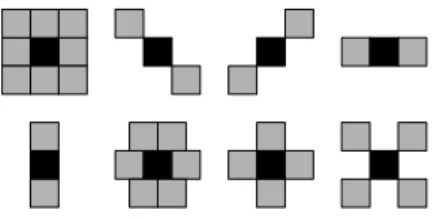
Deselection of registers depends on calculations which must be done with the neighborhood and depends on struc-turing element used (figure 7). For an erosion, deselected pixels must be replaced by the maximum value authorized by the pixel bus width. For a dilation deselected pixels must be replaced by zero. For the median filter, the policy chosen is to replace value of neighborhood as the image border was filled by a checkerboard. The figure 6 shows the principle and how the sort works.
Figure 6:Median Checkboard
Hence border side are correctly processed, pixels go on throw Min/Max tree. This arithmetic unit is presented in fig-ure 4 and could be replaced before synthesis step by a mul-tiply and accumulate tree to compute convolution or by a bubble sort fully pipeline. With such a sort system, we can process every rank filters (erode, dilate and median are spe-cial cases of rank filters). Due to some area constraints we decided to synthesize only the first stage of SPoC with Sort Unit instead of Min/Max tree. It is not necessary to add more stages with bubble sort because the composition rules used for erosion and dilation, which allow us to compose biggest filters, is not valid for others rank filters.
3.3 Programming model
The dedicated architecture could not be addressed directly from video acquisition component because an application could not fit completely into the pipeline and several passes
Figure 7:Some possible SE shapes
with the same images must be performed. That is the rea-son why the pipeline is plugged to the SoC bus to have the opportunity to process several times images in the pipeline. It is able to process multiple pixels at each clock cycle but the general purpose processor in the SoC is not fast enough to feed SPoC with pixels. The processor must just configure DMA to load or store data in FIFO which are written or read by the pipeline. The programming step are shown in figure 8.
Figure 8:Programming Model
4. APPLICATIONS AND BENCHMARK The platform presented in this paper aims to run many em-bedded morphological image processing applications and two examples will be used to benchmark the platform. The first example is a standard video survey motion detection and the second one is a an application of licence plate extraction. The aim in this part is not to build fully robust applica-tions but only benchmark our system against an optimized software implementation with the following architecture:
• Intel Pentium IV running at 3 GHz with 1Mo cache L2
and using SSEx instructions
• Trimedia DSP running at 320 MHz • ARM9 running at 92 MHz
Our SoC is synthesised with a 8-stage SPoC pipeline and running at 100 MHz. The memory allocated, distributed as delay lines in all PoC, is 32 Ko for working with images up to 512 pixels per row. The SoC is routed in a Xilinx FPGA Virtex4 LX 60 and occupy about 21000 slices. SPoC pipeline could be synthesized up to 300 Mhz with Virtex 4 FPGA and up to 400 MHz with Virtex 5.
4.1 Peak computational power
First of all, a benchmark is done to measure, with basic mathematical morphology operations, the peak computa-tional power of our architecture against a Pentium 4, a Tri-media and an ARM. We consider here 512 × 512 8 bits per pixel images, and benchmark operations are size increasing erosions.
PPP
PPPP
Op. Arch. P4 Trimedia ARM Our SoC erosion 1 0.8 8.2 81 1.3 erosion 3 2.5 24 245 1.3 erosion 10 8.3 82 811 1.3 erosion 17 14 140 1379 2.6 Figure 9:computational time for different erosion of 512 × 512 images
The figure 9 shows some timing for erosion of size 1 to 17. A size one erosion corresponds to an erosion 3x3 in 8-connexity. The 6-connexity was also used but timing are al-most the same. Erosion are iterated multiple times to build bigger structuring elements (composition rule of mathemati-cal morphology). We notice for standard processors that the timing grows at each erosion iteration, while the timing for our SoC grows only when second pass is needed. It is worth mentioning that in a 8-stage SPoC, we can map up to 16 ero-sions. A seventeenth erosion could not be mapped in the first pass so a second one is mandatory. So, the challenge for an application is to use as much as possible the whole SPoC pipeline.
4.2 Motion Detection Algorithm
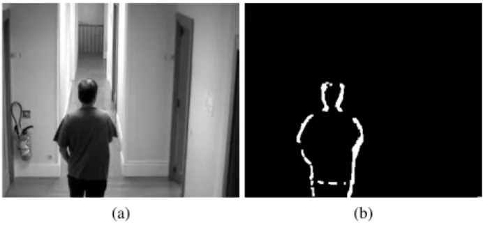
The method used to extract motion objects is not based on optical flow estimation and no a priori on the scene is taken into account. The algorithm is fully described in [9] and it is based on spacial morphological gradient over image links. The formula is given hereafter and images result are pre-sented in figure 11.
mcmt= inf(¯¯gt+1− gt¯¯ ,¯¯gt− gt−1¯¯)
The main advantages of this method is to only memo-rize three successive images to detect motion part of the im-age. However the camera must be fixed to not disturb the detection. If objects to be detected move to slowly regarding the camera frame rate, gradient can not be calculated using
t−1,t,t+1images but t−n,t,t+nsequences. The motion
detec-tion algorithm could be calculated easily by storing at each step the gradient.
Images must be also filtered with alternate sequential fil-ters (Asf) before calculating motion detection in order to re-move noise due to CMOS sensor.
PPP
PPPP
Op. Arch. P4 Trimedia ARM Our SoC
mcm 0.7 3.6 250 1.14
Asf 13.2 121 4103 1.52 Total 13.9 124.6 4353 2.66
(a) (b)
Figure 11:Motion detection Example
(a) (b)
Figure 12:Motion detection Example
The figure 10 shows timing results for each application stage with multiple targeted architectures for 320 × 240 8 bits images. Our SoC performs the application five times faster than a Pentium 4. However “mcm” could not be fully mapped in the pipeline, this implies to do multiple pass, that the reason why timing performance for mcm is weaker than the Pentium 4.
4.3 Licence plate extraction
The method used to extract licence plate is based on adja-cency of characters. A similar method is described in [10]. The algorithm is mainly based on tophat transformations with structuring element of size equal to characters width. Moreover post-filtering is needed to remove false positive detection. Equations are given hereafter and image results are presented in figure 12.
g( f ) = inf( f − γ( f ), ϕ( f ) − f ) (1)
plate( f ) = as f (threshold(g( f ), a)) (2) Timing performance are similar to those obtained with motion detection application and are given in figure 13.
PPP
PPPP
Op. Arch. P4 Trimedia ARM Our SoC g+plate 11,91 103.99 3435 1.95
Figure 13:Licence plate extraction benchmark (in ms)
In this application the SPoC pipeline is better used and our SoC is six time faster than a Pentium 4 even if the clock frequency is 30 times slower.
5. CONCLUSION AND FUTURE WORK The SoC described in this paper is an original system which is powerful for neighborhood processing. The system is not
only able to do mathematical morphology but also convolu-tion. The peak computational power of one PoC processor is 3,20 Gops at 100 Mhz, but this could be greatly improved by using 64 bits memory words and a higher frequency. For example with 32 bits word size and a 400 Mhz frequency, the computational power peak for one PoC will be 12 Gops, that will bring a 8-stage SPoC to 204,8 Gops. The most im-portant challenge with SPoC is to use as much as possible the pipeline, but in real application this is not always possible, so our investigation are oriented to the automatic pipeline gen-eration for dynamic partial reconfigurable architecture and automatic software mapping to schedule efficiently applica-tions parts.
REFERENCES
[1] Dan S. Bloomberg (Editor) John Goutsias (Editor), Luc Vincent (Editor). Mathematical Morphology and Its
Applications to Image and Signal Processing. Springer,
2000.
[2] Pierre Soille. Morphological Image Analysis:
Princi-ples and Applications. Springer-Verlag New York, Inc.,
Secaucus, NJ, USA, 2003.
[3] S.H.D. Hulleman, W. Helbert, H. Chanzy, I. Andreadis, A. Gasteratos, and P. Tsalides. An asic for fast grey-scale dilation. Microprocessors and Microsystems,
20:89–95(7), April 1996.
[4] Hugo Hedberg, Fredrik Kristensen, Peter Nilsson, and Viktor wall. A low complexity architecture for binary image erosion and dilation using structuring element decomposition. In ISCAS (4), pages 3431–3434. IEEE, 2005.
[5] Jaromir Brambor. Algorithmes de la morphologie mathmatique pour les architectures orientes flux. Th`ese
de doctorat en morphologie mathmatique, ENSMP, 2006. Dirige par Michel Bilodeau.
[6] S. Kyo, T. Koga, S. Okazaki, and I. Kuroda. A 51.2-gops scalable video recognition processor for intelli-gent cruise control based on a linear array of 128 four-way vliw processing elements. Solid-State Circuits,
IEEE Journal of, 38(11):1992 – 2000, Nov. 2003.
[7] Wolfgang Raab, Nico Bruels, Ulrich Hachmann, Jens Harnisch, Ulrich Ramacher, Christian Sauer, and Axel Techmer. A 100-gops programmable processor for ve-hicle vision systems. IEEE Des. Test, 20(1):8–16, 2003. [8] J-C. Klein and R. Peyrard. Pimm1, an image process-ing asic based on mathematical morphology. In Second
Annual IEEE ASIC Seminar and Exhibit, pages 7.1.1–
7.1.4, Rochester, September 25-28, 1989, 1989. 1263 CF L-32/90/MM.
[9] L. Biancardini, E. Dokladalova, S. Beucher, and L. Letellier. From moving edges to moving regions. In IbPRIA 2005, Iberian Conference on Pattern
Recog-nition and Image Analysis, page 10, Estoril, Portugal,
June 7-9 2005, 2005.
[10] Antonio Albiol, J. Manuel Mossi, Alberto Albiol, and Valery Naranjo. Automatic license plate reading using mathematical morphology. In Proceedings of the The
4th IASTED International Conference on Visualiza-tion, Imaging and Image Processing, Marbella, Spain,