Science Arts & Métiers (SAM)
is an open access repository that collects the work of Arts et Métiers Institute of
Technology researchers and makes it freely available over the web where possible.
This is an author-deposited version published in:
https://sam.ensam.eu
Handle ID: .
http://hdl.handle.net/10985/19639
To cite this version :
Bastien TOUBHANS, Fabien VIPREY, Guillaume FROMENTIN, Habib KARAOUNI, Théo
DORLIN - Study of phenomena responsible for part distortions when turning thin Inconel 718
workpieces - Journal of Manufacturing Processes - Vol. 61, n°61, p.46-55 - 2020
Any correspondence concerning this service should be sent to the repository
Administrator :
archiveouverte@ensam.eu
Study of phenomena responsible for part distortions when turning thin
Inconel 718 workpieces
Bastien Toubhans
a,b,*, Fabien Viprey
a, Guillaume Fromentin
a, Habib Karaouni
b, Th´eo Dorlin
baArts et Metiers Institute of Technology, LABOMAP, UBFC, HESAM Universit´e, F-71250 Cluny, France bSafran S.A., Research & Technology Center, F-78772, Magny-les-Hameaux, France
A R T I C L E I N F O Keywords: Part distortion Residual stresses Elastic deformation A B S T R A C T
Machining thin workpieces is a challenging task as geometrical errors may result from the combination of several phenomena. Among these, elastic workpiece deformation and machining induced residual stresses may be predominant sources due to low part stiffness. There is a lack of studies trying to quantify the influence of machining induced residual stresses on the total geometrical errors. A thorough experimental methodology is developed to quantify the influence of both phenomena separately by comparing the workpiece shape and di-mensions, in-situ, before and after machining, using laser sensors. The proposed methodology can also be used to quantify the geometrical errors linked to clamping or stress rebalancing following material removal. The case study is the finish turning of thin Inconel 718 workpieces using carbide tools. In the studied case, machining induced residual stresses are responsible for 3–32 % of the total geometrical errors depending on tool wear and cutting parameters.
1. Introduction
The constant pursuit of weight reduction in the aeronautic sector creates new challenges for manufacturers. Indeed, working on thin workpieces increases the risk of geometrical errors during the finishing operations which may lead to the scrapping of high added value parts. Several potential causes of inaccuracy in machining are listed by Ramesh et al. [1,2]. Among those, five phenomena have a prominent role when dealing with low stiffness workpieces. Three of these are linked to workpiece elastic deformation and manifest as modification of the removed material amount. Indeed, low stiffness workpieces tend to vibrate and statically deform when load is applied, either during clamping or cutting. The two other phenomena responsible for geometrical errors are linked to the workpiece stress equilibrium. This equilibrium is disturbed by material removal and the introduction of machining induced residual stresses. The inaccuracy often is the result of combined phenomena. A challenge is to quantify the respective influ-ence of each phenomenon for later be able to anticipate and compensate their effects.
Quantifying the effects of elastic deformation is relatively easy. Indeed, workpiece deformation during cutting or clamping results in local undercut or overcut. Measuring these errors is then possible by
comparing the initial and final part thickness by means of basic measuring instruments, distance sensors, coordinate measuring ma-chines (CMM) or form measuring mama-chines. Recently, Rebergue et al. [3] used Digital Image Correlation (DIC) in order to measure part distortion in-situ on large workpieces. The cutting force related undercut is largely studied in the field of turbine blade machining where variable stiffness and material removal rates along the tool path are problematic [4,5]. The clamping related deformations are minimised by developing intelligent fixture devices [6].The residual stress related phenomena are more challenging to separate and quantify.
In the aeronautic sector, where structural parts are subject to high removal rates, the effect of residual stresses present in the material prior to machining is an important subject. This field of study is demanding for methodologies to determine stress distribution due to elaboration processes. Chatelain et al. [7] studies the effect of different stress dis-tributions in raw aluminium bar stock on the final part distortion after deep pocket milling. A CMM is used to check part distortions. The lon-gitudinal deformation is directly linked to the initial stress distribution. The authors use neutron diffraction method to measure stress distribu-tion through the stock thickness. Richter-Trummer et al. [8] uses the layer removal method to measure stress distribution. These measure-ments are validated by X-ray and neutron diffraction. Machining
* Corresponding author at: Arts et Metiers Institute of Technology, 1 rue porte de Paris, F-71250 Cluny, France. E-mail addresses: bastien.toubhans@ensam.eu, bastien.toubhans@free.fr (B. Toubhans).
induced residual stresses are not studied. Indeed, thermomechanical loads are deemed moderate in the case of high speed machining of aluminium. Schulze et al. [9] uses a simplified approach to introduce controlled plastic deformation into specimens by bending. The stress distribution is then computed by finite element method (FEM) simulations.
In these studies, the effect of machining induced residual stresses is evoked but not clearly quantified. In the case of aluminium, it is often neglected. However, subsurface residual stresses arising from plastic deformation during cutting may be relevant in the case of thin work-pieces. Huang et al. [10] studies the respective effect of stress reba-lancing following material removal and subsurface stress introduction after deep pocket milling in aluminium. By chemically eroding the surface of the finished part, the machining affected zone is removed and the part distortion resulting from this material ablation is subtracted to the total deviation. In this case, machining induced residual stresses are responsible for 10 % of the total part distortion. Masoudi et al. [11] studies the effect of machining induced residual stresses by using workpieces with low stress levels prior to machining. To do so, a special heat treatment is applied to the workpiece before machining to reduce initial stress levels. Yang et al. [12] studies the only effect of machining induced residual stress by mean of FEM simulations. The authors introduce experimentally measured subsurface stress distributions in a refined mesh to assess their effect on distortion. The related distortion increases with the magnitude of residual stresses and the heterogeneity of their distribution under the machined surface.
It appears that all phenomena responsible for part distortions during machining are studied in the literature. However, it is rather complex to separate their respective influence. Additionally, depending on the material and cutting parameters considered, certain phenomena may grow in importance.
When machining nickel based alloys such as Inconel 718, Thakur et al. [13] gathers research findings in a review depicting how cutting conditions may influence cutting forces and surface integrity. Moreover, Sharman et al. [14] and other researchers find that the most influent parameter on surface integrity and cutting forces is tool wear. On the one hand, cutting forces increase with tool wear. The rise may poten-tially reach up to a factor 5 over a standard tool life as shown by Arrazola et al. [15] in turning. Especially the passive cutting force, normal to the machined surface, which is the major responsible for elastic workpiece deformation. A common interpretation is the important ploughing effect linked to adhesion related phenomena and the rubbing of the tool on the machined surface. The decrease in cutting edge sharpness and clearance angle associated with wear progression favour these two phenomena according to Grzesik et al. findings [16]. On the other hand, machining induced residual stresses are also dramatically influenced by tool wear as observed by Sharman et al. [14]. Tool wear tends to increase the affected depth and the magnitudes of tensile stresses at the surface and compressive subsurface stresses. The machining induced residual stresses are resulting from the thermal and mechanical inputs during cutting. Masoudi et al. [11] establishes correlations between surface integrity and cutting forces or temperature in the cutting zone. To do so, residual stress profiles are measured by X-Ray Diffraction (XRD) and the surface areas covered by the stress curves along the measured depth are computed. Although clear trends are observed, it is risky to compare global measurements (force and temperature) with local ones (residual stresses). In this study, an increase in cutting forces or cutting temper-ature leads to more severe stress profiles. Sharman et al. [14] correlates the increase in passive cutting force levels with the increase in depth of maximum compressive stress. To sum up, machining induced residual stresses are widely studied but their influence on geometrical errors is under-explored.
This research work focuses on two phenomena responsible for geometrical errors during turning of thin Inconel 718 workpieces: the machining induced residual stresses and the workpiece elastic defor-mation during cutting. The aim is to quantify their respective influence
on the total geometrical errors. To do so, a decoupling experimental procedure is developed. A first turning configuration aiming at solely inspecting the effect of machining induced residual stresses is presented. The effects of cutting conditions and tool wear on part distortions are assessed. Then, a second configuration is designed to observe both phenomena simultaneously. Thereafter, a methodology to separate and quantify their respective influence is proposed.
2. Scientific approach and experimental procedure
2.1. Scientific approach
This study focuses on the turning of low stiffness workpieces made of Inconel 718. The application is the contour turning, using round tools, of high added value aeronautic parts such as bladed discs or turbine discs. In this section, an experimental procedure aiming at separating the influence of phenomena responsible for geometrical errors is presented. The tests are conducted on a thin disc shaped plate designed to represent the typical problematic shapes encountered when contouring thin workpieces. Face turning operations are performed in order to reduce the disc thickness. The goal is to measure the geometrical errors evo-lution at each step of the process.
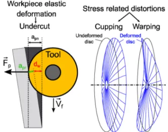
The main challenge is that phenomena responsible for geometrical errors manifest simultaneously during material removal. The different types of distortions are illustrated in Fig. 1. On the one hand, workpiece elastic deformation during cutting manifests as undercut. As the part is pushed away from the tool due to cutting forces, less material is removed. The workpiece elastic displacement is noted dw, the real depth of cut apr and the nominal depth of cut apn in Fig. 1. On the other hand, stress equilibrium modifications manifest as changes in shape such as warping and cupping.
The core principle of this experiment is that part distortions observed on the non-machined back face of the disc, where no material is removed, are only linked to stress equilibrium modifications during cutting. As a consequence, measuring both disc faces geometry allows separating the phenomena responsible for geometrical errors. Further-more, distortions observed on the disc back face are linked to two phenomena modifying stress equilibrium: The introduction of machining induced stress under the machined surface and the reba-lancing of residual stresses present in the material prior to machining following material removal. In order to separate the two, it is possible to use stress free specimen by applying appropriate heat treatment prior to machining. In addition, combining the measurements on both faces gives information on the disc thickness and then on the undercut defect.
Fig. 1. Different types of geometrical errors related to elastic workpiece deformation and machining induced residual stresses.8.
2.2. Experimental procedure Material
The material used in this study is Inconel 718. The discs are manu-factured from round bar stock heat treated to 45 HRC. The raw discs are cut by wire electrical discharge machining and then lapped. The lapping process removes the heat affected zone of the previous operation and enhances the geometrical property. The average total axial run-out measured on the finished discs is 32 μm. The discs are 137 mm in diameter and 3 mm in thickness.
Cutting tool
The cutting operation is performed by using round coated carbide tools with a 4 mm nose radius. The clearance angle, rake angle and inclination angle are respectively equal to 7◦, 0◦and 0◦once mounted on the tool holder. Flood cooling conditions are applied using a water based mixture containing 5% of oil.
Laser measuring procedure
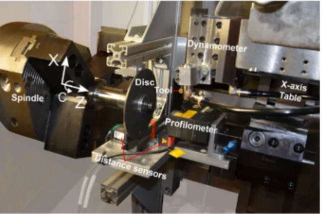
In order to measure the workpiece geometry in-situ, a specific experimental set-up, pictured in Fig. 2, is developed. The laser
technology is chosen as it provides three key advantages: compactness, contactless measurement and sufficient depth resolution. Two laser distance sensors (Micro-Epsilon, ref: optoNCDT 1420-ILD10) are mounted facing each other on a U-shaped plate as illustrated in Fig. 3(a). Each sensor is used to measure shape modifications and displacements on its respective disc face. Combining the two measurements gives in-formation on the local disc thickness. Moreover, a laser profilometer (Keyence, ref: LJ-V7060) is added to the fixture in order to measure the machined surface. Its higher radial resolution gives more information on the machined surface topography.
The measurements are performed inside of the machine between each turning pass. Hence, the laser fixture needs to be easily mounted and dismounted. To this end, the fixture includes a VDI tool holder so it is mounted to the X axis table of the lathe with an evaluated positioning repeatability equal to 8 μm with a maximum error of 20 μm. Conse-quently, the fixture moves along the X and Z-axis of the machine in order to scan the disc as pictured on Fig. 3(a).
The laser measurements are carried out following the flowchart presented in Fig. 4. Firstly, the relative positions of each laser are measured. This way, absolute measurements performed in the machine coordinate system (MCS) are reconstructed in the workpiece coordinate system (WCS). Three characteristic distances are necessary: TransX,
TransZ and D as shown in Fig. 3(b). TransX and TransZ are the X and Z-
Fig. 2. Experimental set-up for turning and measuring disc geometry.10.
Fig. 3. In-situ disc measuring system - a. Laser fixture 3D model - b. Charac-teristic distances.10.
Journal of Manufacturing Processes 61 (2021) 46–55
components of the distances between the middle of the ranges of the profilometer and the front distance sensor. D is the centre of the distance between the beginnings of the two distance sensors ranges. It allows computing the local thickness t in Eq. 1.
t(r, θ) = D − (dback(r, θ) + dfront(r, θ)) (1) Where dback and dfront are the raw distance sensors measurements. To measure those distances, a datum sphere is in-situ scanned along the X- axis by all three sensors. The measured circles are associated with least- square circles. By comparing the centre positions in the MCS, the dis-tances TransZ, TransX and D are deduced.
Secondly, a stationary reference is scanned with the laser profil-ometer in order to cancel resetting error when mounting the fixture. This way, absolute comparison can be done between measurements at different stage of the process, e.g. before and after a machining opera-tion. Lastly, the front and back faces of the disc are scanned thanks to the combination of the X-axis translation and the spindle rotation, i.e. the scanning is achieved in a polar system as shown in Fig. 4.
The distance sensor measurements are performed by continuous acquisition during a full spindle turn at constant speed. This operation is repeated at numerous radial positions (Fig. 4(b). The raw data consists of 37 circles at different radial positions. The lowest radial position accessible to the distance sensors is 32 mm. The profilometer measure-ments are performed by synchronising the acquisition with the spindle position. This is done by using trigger impulsions controlled by syn-chronous actions set into the 840D Siemens CN. The profilometer gather distance information along a 16 mm line as pictured in Fig. 4(a). Four radial positions are sufficient to scan the entire surface of the disc. The raw data consists of 360 radial profiles. The authors encourage the reader to consult the online version for video material detailing the measurement procedure.
After extensive data treatments, the 3D-topographies of the machined surface, back-face and disc thickness are mapped in the WCS as pictured by the coloured height map in Fig. 4.
In this study, the geometrical errors linked to thermal expansion, vibrations, equilibrium rebalancing following material removal, ma-chine accuracy, tool elastic deformation and elastic deformation during clamping are controlled. These phenomena are negligible compared to the two studied phenomena. The flood cooling conditions ensures that the workpiece stays at ambient temperature so the thermal expansion related distortions are marginal. The discs are heat treated in order to reduce the initial residual stresses level prior to machining. This treat-ment consists in maintaining the discs at 600 ◦C for 2 h. A verification test is performed by carefully grinding a slot along one radius of a disc. The total axial run-out is measured using a form-measuring machine, before and after slitting. The variation in total axial run-out is less than 10 μm. A ballbar test (Renishaw, ref: QC20-W) is conducted to control the in-temperature machine geometry. The structural loop geometry in the volume of interest is accurate enough to neglect the machine ge-ometry induced errors. The cutting tool and tool holder assembly
stiffness is simulated by FEM. The tool tip elastic displacement is under 3 μm in the Z direction in the range of cutting forces reached during the tests. Finally, the low flatness error on the discs ensures negligible clamping deformation.
Clamping deformation and equilibrium rebalancing following ma-terial may be important phenomena in certain conditions. In this study, these two phenomena are minimised. However, the previously pre-sented procedure is fit to observe their effects. This research work fo-cuses on machining induced residual stresses and workpiece elastic deformation during cutting. In order to separate the respective influence of each phenomenon, two machining configurations are developed and presented in the next two sections.
2.3. Configuration 1- stiffened disc
In the first configuration, the disc is clamped on a shaft and sup-ported on its back face by a stiff flange as shown in Fig. 5. Consequently, elastic workpiece deformation during cutting is almost entirely cancelled. The objective is to solely observe part distortions linked to machining induced residual stresses. The plastic deformation induced in a thin layer under the machined surface creates residual stresses. Upon removal of the stiff flange, this residual stress field creates a bending momentum resulting in the workpiece deflection. The experimental process is detailed in Fig. 5. The disc is set-up on the shaft and the precision front lock nut is tightened with consistent torque (40 N.m). A first laser measurement cycle previously detailed in Fig. 4b is performed to scan the initial disc geometry, i.e. back and front face form and disc thickness. The stationary reference surface is the front-plane of the surface ground washer. The stiff flange, which is retractable, is set against the disc back face by tightening the back lock nut. Another front face scan is carried out (cf. Fig.4a) to check the deformation during clamping. Then, three face turning operations are performed with a 0.5 mm nominal depth of cut to reduce the disc thickness by half. The machined surface is measured after each pass with the profilometer to check for part distortion. Additionally, cutting forces are measured during the cutting tests using a piezoelectric dynamometer (Kistler, ref: 9121) and a charge amplifier (Kistler, ref: 5019). Tool flank wear facies are acquired in-situ with a digital microscope after each pass to avoid disassembling the tool. The face turning begins at the diameter 137 mm and finishes at 64 mm during the first pass. Then, for the second and third pass, the tool is disengaged at the diameter 66 and 68 respectively. This is to avoid a rapid chip load increase at the end of the current pass due to uncut material at the end of the previous pass. After the third pass, the stiff flange is removed. Then, a last measuring procedure is performed to characterise the disc geometry after the machining pro-cess. Part distortions linked to machining induced residual stresses are observed by comparing the disc geometry during laser cycle 1 and 6 on
Fig. 5.
This configuration allows observing part distortions solely linked to machining induced residual stresses. In the next section, a second
Fig. 5. Measuring procedure and machining steps - Stiffened disc configuration N◦1.16.
Journal of Manufacturing Processes 61 (2021) 46–55
configuration is developed to also observe geometrical errors linked to elastic workpiece deformation during cutting.
2.4. Configuration 2- free disc
In this second configuration, the disc is clamped on a shaft and free to elastically deform during cutting as shown in Fig. 6. Thus, the depth of cut is variable along the pass contrary to the first configuration. The aim is to observe both phenomena simultaneously. And finally to separate their respective influence on the total geometrical errors. To do so, the disc thickness is measured with both laser distance sensors to determine the local undercut defect linked to elastic deformation. Additionally, the disc back face is scanned to check for shape evolutions due to machining induced stresses.
The experimental process is detailed in Fig. 6. The disc is set-up on the shaft. Similarly to the first configuration, a laser cycle is performed with the locknut firmly tightened to assess the initial disc geometry. The stationary reference surface is still the front-plane of the surface ground washer. Then, three face turning operations are performed with a 0.5 mm nominal depth of cut. The face turning begins at the diameter 137 mm and finishes at 49 mm during the first pass. Then, the tool is dis-engaged at the diameter 51 and 53 respectively for the second and third pass for the same reason evoked in section 2.3. The difference in diameter range in the two configurations is explained by the use of a larger diameter washer in the first configuration in order to tighten the disc against the stiff flange. A laser cycle is performed after each pass. Cutting forces and tool wear facies are also acquired during the experiments.
In the next two sections, the two configurations are tested. The studied phenomena are thoroughly observed and analysed. In the last section, the methodology detailed in section 2.1 is applied to separate the effect of elastic workpiece deformation and machining induced
residual stresses on geometrical errors.
3. Study of geometrical errors resulting from machining induced residual stresses - Stiffened disc
In this section, the effect of machining induced residual stresses on part distortion is studied. Different cutting conditions and tool wear levels are tested.
3.1. Experimental conditions
The experiment involves machining tests on 6 discs with different conditions summed up in Table 1. The cutting conditions are consistent with semi finishing and finishing conditions identified in [17]. The tests consist in 3 consecutive face turning passes. The average disc thickness and total axial run-out are displayed in Table 1, before and after machining. Moreover, the total machining time and maximum flank wear level VB reached after three passes are displayed. A different cut-ting insert is used for each disc. For the discs E and F, the tools are worn beforehand on a massive workpiece to reach the critical wear VBc using the same cutting parameters. Practically, the preliminary wearing tests are stopped when an inflexion is observed on the cutting forces evolu-tion curves. The critical flank wear VBc, ranging between 0.15 and 0.2 mm, marks the end of the controlled wear region during which cutting forces evolve quasi linearly.
As described in Fig. 5, both disc faces are scanned before and after machining while the disc is firmly tightened to the shaft, respectively during laser cycles N◦1 and 6. Comparing the back face geometry be-tween these two stages gives the distortions linked to machining induced residual stresses.
Fig. 6. Measuring procedure and machining steps - Free disc configuration N◦2.17.
Table 1
Cutting conditions used in the Stiffened disc configuration - Disc geometry criteria after machining.
Experimental conditions Initial disc features Disc features after 3 face turning passes Disc Vc (m/
min) f (mm/ tr) a(mm) p h(mm) max Tool initial condition Total axial run- out (μm) Thickness (mm) Total axial run- out (μm) Thickness (mm) Total machining time (min) VB (mm)
A 52.5 0.1 0.5 0.047 Fresh 23 2.988 63 1.54 6.5 0.14 B 52.5 0.2 0.5 0.093 Fresh 24 2.946 92 1.49 3.2 0.14 C 52.5 0.35 0.5 0.157 Fresh 21 2.943 117 1.46 1.8 0.12 D 70 0.1 0.5 0.047 Fresh 22 2.951 107 1.46 4.9 0.14 E 52.5 0.2 0.5 0.093 VB=0.16 39 3.023 603 1.55 14.2 0.26 F 70 0.1 0.5 0.047 VB=0.15 32 2.957 422 1.52 13.5 0.23 B. Toubhans et al.
3.2. Results and discussions
All six discs present distortions varying in magnitude and direction. The back face displacement is quasi-axisymmetric in all cases as shown in Appendix. (cf. cupping distortion in Fig. 1). For this reason, the average displacement profile of the back face at each radial position is illustrated in Fig. 7. The back face average displacement is computed by subtracting the average back face profile before and after machining (step N◦1 and 6 on Fig. 5). As a reminder, the laser measurements start at the 32 mm radius for accessibility reasons. However, the disc is pressed against the shaft up to the 20 mm radius (marked by a blue pointer on
Fig. 7).
The machining induced residual stresses, in the radial and circum-ferential direction, disturb the workpiece equilibrium and create a bending momentum. Generally speaking, the amount of distortion is linked to the workpiece geometry and this bending momentum. In the studied case, the final discs thicknesses are comparable (cf. Table 1) so the difference in distortion magnitude is explained by the machining induced residual stresses only.
Depending on the repartition between tensile and compressive stresses along the machining affected depth, the disc bends backward or inward. Similarly to an Almen test, used in shot-peening, a backward bend indicates a mostly compressive stress profile. As mentioned in the introduction section, machining with a worn tool may create high ten-sile stresses close to the machined surface. However, the affected depth and magnitude of the compressive peak are also significantly increased compared to machining with a fresh tool [14,17]. Based on these bibliographic knowledge and experimental observations, it is deduced that the residual stress profiles obtained with a worn tool are highly compressive in the studied case. This observation appears on disc E and F where massive backward bends are measured. Concerning discs A, B, C and D, machined with fresh tools, the distortion magnitudes are lower but still significant considering the final disc thickness equal to 1.5 mm. On disc A, B and C, increasing the feed inverts the bending direction from backward to forward. At the same time, the distortion magnitude
increases. This may mean that tensile stresses are predominant at this stage of the cutting process when using higher feed. Even though re-sidual stress profiles significantly vary during tool life, several studies show that the effect of wear on surface integrity is moderate in Inconel 718 until the flank wear reaches a critical level [15,17]. Over this level, a major increase in cutting forces and machining induced residual stresses affected depth is observed. This may explain the difference in distortion magnitude observed between the discs machined with a fresh tool and those with a pre-worn tool.
In the next section, the effect of both machining induced residual stresses and workpiece elastic deformation on part distortion is studied. 4. Study of geometrical errors resulting from workpiece elastic deformation and machining induced residual stresses - Free disc
These investigations are supported by tests consisting in 3 consecu-tive face turning passes on 4 discs with different conditions summed up in Table 2. The original disc average thickness and total axial run-out are also displayed in Table 2. A different cutting insert is used for each disc. For the disc J, the tool is worn beforehand using the same procedure detailed in section 3.1.
4.1. Undercut analysis
In this configuration, the disc is free to elastically deform during machining. It results in an undercut defect in addition to part distortion linked to machining induced residual stresses. The Machined surface average Profile (MPi) is plotted on Fig. 8 at different stages of the experimental process; before machining and after each pass for disc H. Additionally, the disc envelop (swept volume) is represented by a col-oured patch. So it represents the flatness error or amount of warping in the disc at each step. The disc is firmly clamped to the shaft during these measurements. The three passes are performed with a nominal depth of cut (apn) equal to 0.5 mm. The disc stiffness varies along the pass to reach a maximum close to the disc anchor point at the end of the pass. Indeed,
Fig. 8 shows that this nominal depth of cut in only reached at the end of the pass. In addition, the undercut is decreasing close to the tool entry point. It is explained by the progressive increase of the cut section during tool engagement (transient state). The undercut error accumulates pass after pass leading to significant thickness heterogeneity in the final part. The dashed lines labelled NPi are the Nominal Profiles which would be obtained after each pass if the disc and tool were perfectly stiff.
The undercut is axisymmetric as indicated by the low circular axial run-out evolution and the 3D maps displayed in Appendix. In fact, the slight increase in circular axial run-out is attributed to warping due to stress rebalancing during machining. Furthermore, the gap between the nominal profile and the average machined profile is linked to the un-dercut and the bending of the disc due to machining induced residual stresses. At this point, it is impossible to quantify the two phenomena separately. This issue is tackled in the paragraph 4.2 by using the back face measurements.
The average undercut is defined as the difference between the tool- workpiece interference before the pass and the actual local material thickness removed during the pass. It is calculated according to Eq.2
where MP and NP are respectively the average and nominal profile of the
Fig. 7. Average displacement measured on the disc back face after 3 face turning operations in the stiffened disc configuration - 6 discs tested with different cutting conditions.20.
Table 2
Cutting conditions used in the Free disc configuration.
Experimental conditions Initial disc features Disc features after 3 face turning passes Disc Vc (m/
min) f (mm/ rev) a(mm) p h(mm) max Tool initial condition (Total axial run-out μm) Thickness (mm) Total axial run-out (μm) Total machining time (min) VB (mm)
G 52.5 0.1 0.5 0.047 Fresh 93 2.96 0.725 7.3 0.14
H 52.5 0.2 0.5 0.093 Fresh 45 2.963 0.768 3.6 0.14
I 70 0.1 0.5 0.047 Fresh 80 3.005 0.631 5.4 0.29
machined surface before the pass highlighted in Fig. 8. The real depth of cut apr is computed by subtracting the disc thickness, measured with the two distance sensors, between two consecutive tool passes. The expression (MP–NP) in Eq.2 depicts the error accumulation pass after pass. Indeed, the undercut and the bending which happen during the first pass add to the nominal tool/workpiece interference of the second pass.
Undercuti=a⏟̅̅̅̅̅̅̅̅̅̅̅̅̅̅̅̅̅̅̅̅⏞⏞̅̅̅̅̅̅̅̅̅̅̅̅̅̅̅̅̅̅̅̅⏟pn i+ (MPi− 1− NPi− 1) Tool/workpiece interference
− ⏟̅⏞⏞̅⏟apr i Real depth of cut
(2) The average undercut and passive force evolutions along the tool path are illustrated in Fig. 9 for each cutting test. The measured undercut is maximal close to the outer diameter of the disc where it is less stiff. As a consequence, the undercut accumulates faster close to the outer diameter. The measured passive force increases and reaches its maximum at the end of the pass where the disc is the stiffest. Only one pass is performed on disc J due to the extent of undercut obtained during the first pass with a pre-worn tool. In all three tests with a fresh tool (G, H and I), the measured passive forces evolutions are comparable. Consequently, the undercut are also comparable for these three discs. The differences are explained by the heterogeneity in initial disc thick-ness, the operator error when setting the first pass depth of cut and the slight difference in passive cutting force during the passes. Furthermore, rapid wear is observed during the third pass for the test at Vc =70 m/min and f =0.1 mm/rev. The passive force evolution during this test is not consistent with the one observed on a massive workpiece. It may be explained by the reduction of chip thickness inducing higher specific energy at the beginning of each pass on a free disc. Concerning the test on disc J performed with a pre-worn tool, the maximum undercut is multiplied by two during the first pass compared to the tests using a fresh tool. As one can see in Fig. 9, machining the disc with a pre-worn tool may cause cut refusal if the workpiece is not stiff enough. Indeed, the undercut error is almost equal to the nominal depth of cut at the beginning of the pass.
In addition to undercut, elastic deformations linked to machining induced residual stresses are measured on the disc back face after each pass.
4.2. Machining induced distortion analysis
When turning with a tool in the controlled wear region, XRD mea-surements show that the machining-affected area depth is inferior to 0.15 mm (cf. [17]). Considering the fact that the average effective depth of cut is always greater than 0.15 mm as shown in Fig. 9, it is reasonable
to assume that the current pass erases the machining affected area of the previous pass. Hence, the relative displacement measured between the initial clamped disc geometry and the current pass is attributed to re-sidual stresses introduced during the current pass. For this reason, the average displacements measured on the disc back face relative to the initial clamped disc geometry are displayed in Fig. 10. Backward bends, proper to a mostly compressive stress profile, are observed in every cutting test except for the first pass on disc H where a forward warping is measured. The average displacement representation proposed in Fig. 10
is not appropriate for non-axisymmetric distortions; however, it only concerns this particular pass. Furthermore, the distortion magnitude obtained after a single pass on disc J, with the worn tool, exceeds the one obtained after 3 passes on the 3 other discs with fresh tool. It supports the observation that tool wear has an important impact on machining induced residual stresses.
It is not relevant to compare the distortions magnitudes observed in the “stiffened” and “free disc” configurations as the diameter range and the disc geometry (mostly the removed thickness) after the third pass are different. Also, the machining induced residual stresses are different as the real depth of cut varies along the pass in the “free disc” configuration.
To sum up, the studied procedure allows precise measurement and separation of the geometrical errors linked to workpiece elastic defor-mation and machining stress induced distortions. In the next paragraph, the separation methodology is applied and the respective influence of both phenomena on total geometrical error is quantified.
4.3. Respective influence of both phenomena on geometrical errors During the tests achieved in the “free disc” configuration, two types of geometrical error are identified. On the one hand, the undercut is principally associated with workpiece elastic deformation during cut-ting. On the other hand, the back face distortion is associated with machining induced residual stresses. In order to quantify the respective influence of both phenomena on the total geometrical error, three geometrical criteria are chosen. The first one is the maximum undercut error (Um) given in Fig. 9 which describes the workpiece elastic defor-mation error. The second one is the maximum displacement (dm) measured on the back face (Fig. 10). The last one is the increase in circular axial run-out at the outer diameter (δcar) as pictured in Fig. 8. The sum, dm + δcar, regroups the bending and warping distortions resulting from machining induced residual stresses. Finally, a fourth geometrical criterion called the total geometrical error (Σe) represents the sum of the three previous criteria (cf Eq. 3).
Σe= Um+dm+δcar (3) These criteria are gathered in Table 3 in addition to the machining time (tm) and the maximal flank wear (VB) for each test. The relative influence of each phenomenon on the total geometrical error is dis-played in Fig. 11. The value of each criterion is also indicated on the bar graph in μm.
First of all, the geometrical error linked to workpiece deformation
during cutting is predominant in all cases in this study. Besides, the influence of machining induced residual stresses ranges from 3–32% of the total geometrical errors. Therefore, this phenomenon cannot be neglected in the studied case. Due to the accumulation of undercut, the proportion linked to workpiece elastic deformation increases pass after pass for disc G and I. However, for disc H, the first pass causes a com-parable amount of undercut but rather low stress induced distortion. As observed in section 3.2, modifying the cutting conditions may help minimize the influence of machining induced residual stresses on part distortion by creating lower bending momentums.
When using a worn tool, all geometrical criteria: Um, dm and δcar are maximal and the residual stress induced distortions have more influence on the total geometrical error than when fresh tools are used. Further-more, it can be noted that the cutting force levels and maximum flank wear reached at the end of the first pass on disc J, are less critical than the one reached in the “stiffened disc” configuration. In fact, despite being pre-worn prior to machining disc J, the tool used was still in the controlled wear region during the pass. It is highly probable that cut refusal and higher stress related distortions may have occurred with an even more worn tool.
Lastly, the relative influence of each phenomenon depends on the workpiece geometry. For example, the bending stiffness increases with the cube of the workpiece thickness. One could argue that if the same cutting forces and machining induced residual stresses were applied to two parts with different thicknesses, the magnitude of each criterion would be different but their respective proportion would be the same. In the case of a thicker workpiece, the undercut is lower and then the real depth of cut increases. As a consequence, the machining induced re-sidual stresses are different and then the proportion linked to stresses
Fig. 9. Instantaneous average passive force and average undercut measured for each test - Free disc.25.
Fig. 10. Average displacement from initial state, measured on the disc back face after each 3 face turning operations - 4 discs tested with different cutting conditions.27.
Table 3
Geometrical criteria linked to both phenomena for each test - total machining time and associated flank wear.
Disc Pass Um (μm) d(μm m) δ(μcar m) Σ(μe m) t(min) m VB (μm) G 1 2 267 472 62 87 −5 5 324 564 2.4 4.9 113 123 3 748 105 −5 848 7.3 143 H 1 2 256 517 13 13 9 3 278 533 1.2 2.4 98 122 3 794 55 13 862 3.6 137 I 1 2 216 443 76 138 −0 6 286 581 1.8 3.7 137 219 3 680 167 4 851 5,4 290 J 1 453 216 1 670 12 208
varies. 5. Conclusions
This study presents a thorough experimental methodology aiming at quantifying the respective influence of in-process workpiece elastic deformation and machining induced residual stresses on the total geometrical errors is tested. This methodology can also be used to quantify the influence of clamping and residual stress rebalancing following material removal. Moreover, this methodology can be applied to all kinds of metallic materials in order to quantify the effect of machining induced residual stresses depending on their machinability. The key conclusions are:
•Part distortions induced by subsurface machining residual stresses are not negligible in the studied case compared to workpiece elastic deformation during cutting. It represents between 3% and 32 % of the total geometrical errors depending on the cutting conditions as well as tool wear.
•Tool wear has an important impact on geometrical errors. It greatly influences both cutting forces and machining induced residual stresses. Hence, it increases the geometrical errors linked to both studied phenomena. The proportion linked to machining induced residual stresses is higher when using a worn tool.
This study answers an important question about machining accuracy during finishing operation on low stiffness Inconel 718 workpieces. It proves that machining induced residual stresses play an important role in part distortion. To this day, modelling of equilibrium rebalancing following material removal is well-advanced and gives satisfying results when dealing with massive workpieces. However, when working on low stiffness workpieces, these modelling solutions fall short and cannot accurately predict post machining distortions. An interesting perspec-tive would be to complement existing methodologies with the effect of machining induced residual stresses in the machining affected subsurface.
Declaration of Competing Interest
The authors report no declarations of interest. Acknowledgements
This research did not receive any specific grant from funding agencies in the public, commercial, or not-for-profit sectors.
Appendix A
Figs. A1 and A2.
Fig. 11. Respective influence of undercut and machining induced residual stresses on total geometrical error.29.
Fig. A1. Quasi-axisymmetric back face displacement (iso scale) for the 6 discs tested in the stiffened disc configuration. Displacement obtained after 3 face- turning passes between laser cycle N◦1 and N◦6 in Fig. 5.
Fig. A2. Quasi-axisymmetric undercut error during 3 face turning operations (iso scale) for the 4 discs tested in the free disc configuration.
Appendix B. Supplementary data
Supplementary material related to this article can be found, in the online version, at doi:https://doi.org/10.1016/j.jmapro.2020.11.007. References
[1] Ramesh R, Mannan MA, Poo AN. Error compensation in machine tools — a review: part I: geometric, cutting-force induced and fixture-dependent errors. Int. J. Mach. Tools Manuf. 2000;40(9):1235–56.
[2] Ramesh R, Mannan MA, Poo AN. Error compensation in machine tools—a review: part II: thermal errors. Int. J. Mach. Tools Manuf. 2000;40(9):1257–84. [3] Rebergue G, Blaysat B, Chanal H, Duc E. Advanced DIC for accurate part deflection
measurement in a machining environment. J Manuf Process 2018;33:10–23. [4] Ma J, He G, Liu Z, Qin F, Chen S, Zhao X. Instantaneous cutting-amount planning
for machining deformation homogenization based on position-dependent rigidity of thin-walled surface parts. J Manuf Process 2018;34(Part A):401–11. [5] Wang J, Ibaraki S, Matsubara A. A cutting sequence optimization algorithm to
reduce the workpiece deformation in thin-wall machining. Precis Eng 2017;50 (Supplement C):506–14.
[6] Gonzalo O, et al. A method to minimize the workpiece deformation using a concept of intelligent fixture. Robot. Comput.-Integr. Manuf. 2017;48:209–18.
[7] Chatelain J-F, Lalonde J-F, Tahan AS. A comparison of the distortion of machined parts resulting from residual stresses within workpieces. Proc 4th Int Conf Manuf Eng Qual Produ Syst MEQAPS’11 2011:79–84.
[8] Richter-Trummer V, Koch D, Witte A, dos Santos JF, de Castro PMST. Methodology for prediction of distortion of workpieces manufactured by high speed machining
based on an accurate through-the-thickness residual stress determination. Int. J. Adv. Manuf. Technol. 2013;68(9–12):2271–81.
[9] Schulze V, Arrazola P, Zanger F, Osterried J. Simulation of distortion due to machining of thin-walled components. Procedia CIRP 2013;8(Supplement C): 45–50.
[10] Huang X, Sun J, Jianfeng Li. Finite element simulation and experimental investigation on the residual stress-related monolithic component deformation. Int. J. Adv. Manuf. Technol. 2015;77(5–8):1035–41.
[11] Masoudi S, Amini S, Saeidi E, Eslami-Chalander H. Effect of machining-induced residual stress on the distortion of thin-walled parts. Int. J. Adv. Manuf. Technol. 2015;76(1–4):597–608.
[12] Yang L, Sun Y, Zhuang C, Xiong Z. Distortion prediction of a dual-disc part by turning-induced residual stresses mapping. 9th Int. Conf. Digit. Enterp. Technol. – Intell. Manuf. Knowl. Econ. Era, 56; 2016. p. 249–54.
[13] Thakur A, Gangopadhyay S. State-of-the-art in surface integrity in machining of nickel-based super alloys. Int. J. Mach. Tools Manuf. 2016;100:25–54. [14] Sharman ARC, Hughes JI, Ridgway K. The effect of tool nose radius on surface
integrity and residual stresses when turning Inconel 718™. J Mater Process Technol 2015;216:123–32.
[15] Arrazola PJ, Garay A, Fernandez E, Ostolaza K. Correlation between tool flank wear, force signals and surface integrity when turning bars of Inconel 718 in finishing conditions. Int. J. Mach. Mach. Mater. 2014;7(1–2):84–100. 15. [16] Grzesik W, Niesłony P, Habrat W, Sieniawski J, Laskowski P. Investigation of tool
wear in the turning of Inconel 718 superalloy in terms of process performance and productivity enhancement. Tribol Int 2018;118(Supplement C):337–46. [17] Toubhans B, Fromentin G, Viprey F, Karaouni H, Dorlin T. Machinability of inconel
718 during turning: cutting force model considering tool wear, influence on surface integrity. J Mater Process Technol 2020:116809.