Science Arts & Métiers (SAM)
is an open access repository that collects the work of Arts et Métiers Institute of Technology researchers and makes it freely available over the web where possible.
This is an author-deposited version published in: https://sam.ensam.eu Handle ID: .http://hdl.handle.net/10985/8683
To cite this version :
Patrice DUBOIS, Améziane AOUSSAT, Marc LE COQ - A method to Formalise the Rapid Prototyping Process - International Journal of Computer Applications in Technology - Vol. 12, n°2/3/4/5, p.245-256 - 1999
A method to Formalise the Rapid Prototyping Process
Dubois P. - Aoussat A. - Le Coq M.
ENSAM New Products Design Laboratory
151, Boulevard de l’Hôpital 75013 Paris
Abstract:
Facing the increasing complexity of the product design area, (reduction of cycle times, introduction of simultaneous engineering, introduction of digital mock-up, ... ) a research department which wants to define a rapid prototyping process is confronted to the problem of the tools’ choice.
Therefore, we will propose in this article, a method allowing to conceive such a process.
In a first chapter, we present the rapid prototyping area in the product design environment, in a second chapter we will propose our method illustrated by an industrial case.
Key words: Products design, Simultaneous Engineering, Rapid prototyping, CAD/CAM, Design, 3D digitizing sensor, digital mock-up.
1. Introduction
Facing the internationalization of markets, enterprises are confronted to a more and more quick competition. In this context, an enterprise that wishes to acquire new parts of market must be competitive and must develop new products. Therefore, competitiveness becomes synonymous of reactivity [CAR 92].
To create, to innovate and to produce products in very short times, have became essential factors of success for enterprises: they must adapt their design process to these new criteria but also must consider the new technologies emerging, as the rapid prototyping.
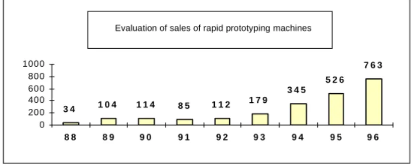
Appeared in 1987 [DOL 94], this new technology offers the possibility to engineers to materialize without specific tooling a CAD object. Imposing itself progressively in research department (see figure 1) the domain of the rapid prototyping enriched itself of complementary techniques like the ‘reverses engineering’ and the rapid duplication of shapes.
However, the main difficulty for reseach department engineers is the passage of the theoretical model to the concrete model which must satisfy the need of the enterprise. Indeed, facing the diversity of tools proposed, this one is confronted to the problem of the choice. To solve this problematic, we consider the domain of the rapid prototyping, no more as a simple assembly of tools, but like an assembly of functions. So, the first stage consist identifing those functions ; in the second stage, we research tools which satisfy them.
In our communication, we will present in a first chapter the rapid prototyping and its tools in the product design environment; then in a second chapter, we will propose to engineers a method for the choice of tools in order to assure their integration in a product design process.
Figure 1: Evaluation of sales of rapid prototyping machines (FreeForm Fabrication) Est imat i o n d es vent es mo nd i al es d e machi nes
( no mb r e d ' unit és) 3 4 1 0 4 1 1 4 8 5 1 1 2 1 7 9 3 4 5 5 2 6 7 6 3 0 200 400 600 800 1000 8 8 8 9 9 0 9 1 9 2 9 3 9 4 9 5 9 6
2.
The rapid prototyping environment
In this chapter, we will show the interest of using rapid prototyping technics regarding the economical, human and technical environment of the product design.
2.1
The product design environment
Since some years the product design environment evolved strongly. Industrial confronted to a strong competition must decrease time limits of development, to decrease costs and to improve the quality, imperatively. To answer to these objectives, we attend on the progressive introduction of the simultaneous engineering [CAR 92]. This method of product development takes in consideration all functions of firm. Therefore, the life cycle of a project takes the technical, economical, social and organizational aspects, research and development, marketing and commercial, and management considerations [BOU 94]. Thus, the multidisciplinary teams must work simultaneously in parallel, the earliest possible toward one same goal. Another characteristic is that, this approach is supported by technologies of information and communication. All information must be able to arrive in real time to the different actors (see figure 2). The computer environment appeals different areas of which information systems (tool of data exchange, data base techniques,....) and softwares (tools of CAD/CAM, tools of simulation, codes of finite elements,....) [ADI 97].
Figure 2: The computer model of the Competitor Engineering [JAG 94] Bureau des
Méthodes R et D
Bureau
d'études Logistique desoutien Qualité
Equipementiers Sous-traitants Base de données Techniques Fournisseurs Réseau Local R & D Research consultancy Tooling
design Logistic Quality
Network
Subcontractors Data bank Suppliers
In this context, the digital model approach begins to be used in the big enterprises: mainly the aeronautic and the automobile constructors. This one may be characterized by three successive stages:
“1 - the implementation of software of CAD/CAM and the complete digitizing of the product,
2 - the digital mock-up that, from CAD data, allows the visualization in real time of the final product and the simulation of manufacture processes,
3 - the virtual prototyping that from the digital model, allows to achieve all studies of behavior and the simulation of the installation in a virtual factory.” [HOU 97]
According to the constructor of RENAULT cars, the substution of the physical model serving support to their studies by the digital model must permit the reduction of product development cycle time. Thus, the generalization of the use of the digital model makes appear:
- information exchanged between the different users or intervening parties in the chain of process rests on only one reference: the digital model;
- savings come of a decision hold to the earliest, of a work in real time from different places. - a reduction of models and prototypes (economy of time and money).
Nevertheless it is important to specify that the context presented hereabove is in constant improvement. Indeed, some difficulties persist:
• exchanges of data between different CAD systems are not 100% reliable: many works are in progress on the definition of an standard exchange format (STEP). [MAS 98]. In this context, to join two objects conceived on different systems and validate the assembly can present some difficulties : the geometry of objects can be affected during the transfer,
• some professions as designers feel difficulties to work with the digital tools and always continue to express themselves through models and physical prototypes (it is however important, to specify that some designers use virtual reality, CAD systems and their model since several years),
• numerous enterprises only begin to equip themselves in CAD softwares : investments in materials and in formation are expensive,
• human always needs his five senses to judge and to validate shapes of an object: it is more difficult to appreciate digital mock up on a screen that on a physical model.
Therefore, in this context, it is necessary to arrange tools permitting to materialize objects quickly consistently to the CAD definition but also to do the path reverses: “to go up again” shapes of a physical object toward the CAD model. The rapid prototyping is an element of answer to this problematic.
2.2
The rapid prototyping
2.2.1 General objective
The rapid prototyping regroups different techniques and technologies whose goal is the fast obtaining of model and prototype according to the definite need. It is a combination of techniques that associates or integrates before or/and after a of rapid manufacturing process of shapes [MIC 95]. The rapid prototyping permits to lead to different types of models and prototype permitting to fill various functions during the process of product development (see figure 3) [BAR 93]. Thus, it is possible to validate the aesthetic aspect of an object, its geometry and functions that it must fill (assembly, ergonomic,...). [BER 97]. These techniques are also used for the building of rapid tooling permitting to validate manufacturing process. [BAR 98]
Figure 3: Types of model and prototype achieved by rapid prototyping during the process of product
development according to Baraldi [BAR 93]
Rapid prototyping
Product Design Process
Later series prototypes (until 500 models)
Determination and validation of manufacturing process parameters.
β Test
The material is good.
Technical prototype (2 to 5 models)
All functionnal aspects of a model but the manufacturing process is different from the one which will be used in the series production. The material may be different
Functionnal prototype (2 to 5 models)
Function all aspects which are represented as a set of features are reviewed ( sub system of a product)
Geometrical prototype (1 model)
Employed for testing accuracy, form and fit of the later series parts. The focus is on geometry and not on the material aspects
Design prototype (1 model)
Design review under the consideration of optical, esthetical and ergonomical requirements
2.2.2 The rapid prototyping: a diversity of tools
One can consider that the rapid prototyping can divide itself in three big domains: • reverses engineering,
•the rapid manufacturing of shape, •the rapid duplication.
These three domains that we will detail allow to characterize the digital chain of the rapid prototyping presented below on the figure 4 below.
Figure 4: Digital chain of the rapid prototyping
Mock-up Digitizing
Reconstruction of surfaces model CAD CAM CN milling Rapid Prototyping Lost vax casting Vacuum casting Physicalmodel Resin model Metallic model Digital model R e v e rs e en g in e er in g R a p id ma nu fa c turin g of f o rm s R a p id du p ic a ti o n Reverses engineering
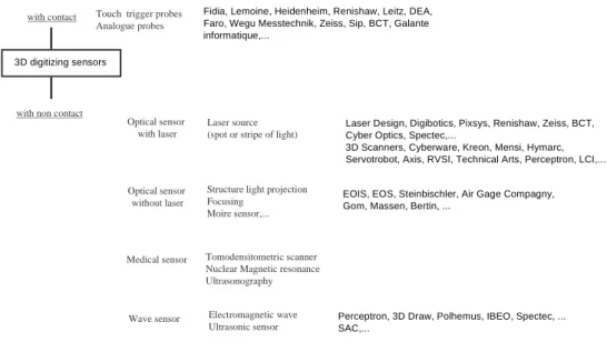
Reverses engineering consists in creating the digital model of an object in order to replicate it, to achieve a prototype of it or to manufacture the tooling. Its principle needs the utilization of digitizing tools permitting to acquire the morphology of a 3D object with clouds of points. The treatment of this data is achieved by a specific software as Surfacer sofware (Imageware). The digitizing of 3D object is also used for applications of dimensional control (comparison to the CAD model), in the medical domain (characterization of organ, adaptation of prothesis)[BOU 96] and the reproduction of stage (architecture, archeology,...). There are many 3D digitizing systems. The figure 5 presents the different present constructors existing on the market according to the technology employee. One will be able to notice that the offer is varied.
The main parameters permitting to characterize a sensor of shapes are the resolution, the precision, the time of measure and the computer treatment time. Nevertheless, it doesn't exist any precise rules in matter of choice of the technology and the sensor.
3D digitizing sensors
with contact
with non contact
Touch trigger probes Analogue probes
Structure light projection Focusing Moire sensor,... Optical sensor with laser Medical sensor Laser source (spot or stripe of light)
Tomodensitometric scanner Nuclear Magnetic resonance Ultrasonography
Electromagnetic wave Ultrasonic sensor Wave sensor
Fidia, Lemoine, Heidenheim, Renishaw, Leitz, DEA, Faro, Wegu Messtechnik, Zeiss, Sip, BCT, Galante informatique,...
Laser Design, Digibotics, Pixsys, Renishaw, Zeiss, BCT, Cyber Optics, Spectec,...
3D Scanners, Cyberware, Kreon, Mensi, Hymarc, Servotrobot, Axis, RVSI, Technical Arts, Perceptron, LCI,....
EOIS, EOS, Steinbischler, Air Gage Compagny, Gom, Massen, Bertin, ...
Perceptron, 3D Draw, Polhemus, IBEO, Spectec, ... SAC,...
Optical sensor without laser
Machines of rapid prototyping
As we already indicated, it exists two ways for the rapid manufacturing forms: - by machining ( NC milling ) (not treated here)
- by processes of free forms fabrication by layers.
The model or the prototype achieved are constructed in three measurements by sequential stacking of fine horizontal layers. The most known technology is stereolithography and is also the most ancient (first available technology on the market in 1998) [NO 93] [DOL 94].
One can affirm that processes of manufacture by layers revolutionized the manufacture of model and prototype: this kind of manufacturing doesn’t need to use some special toolings to obtain models [BOUR 96]. To dispose of physical model quickly according to the digital definition permits to detect all type of mistake (of shape, functional) that appears during the product design time [MIC 95].
The figure 6 represents an ordering of technologies according to the method of transformation of the material used [ADI 95]. According to processes, materials employed can be some photosensitive liquid resins (acrylates, epoxydes), of materials in leaves (metals, paper, plastic) of thermoplastic materials, metallic, plastic, ceramic powders.
"2D" (sheet) Liquid Solid "0D" (powder particles) •Stereolithography (Laser) - 3D Systems (USA) - EOS (D) -CMET(J) - D-Mec (J) - Teijin Seiki (J) - Laser 3D (F) - Fockele & Schwarze (D)
•Photomasking (UV)
Solid Ground Curing (Israël) Cutter and laminate •Laminated Object Manufacturing Helisys (USA) •Stratoconcept ion Cirtes (F) •Hot plot Spark (S) Fused deposition filament •Fused Deposition modeling Stratasys (USA) Laser sintering •Selective laser sintering DTM (USA) •EOSINT EOS (D) •Model maker Sanders (USA) •Cubital (Israêl)
Three dimensional printing
•Direct Shell Production Casting Soligen (USA)
•Actua 2100 3D Systems (USA)
•Ballistic Particle Manufacturing BMP Technology (USA)
"1D" (filament)
It is important to specify that processes do not allow to disposed of classified model “good matter” (matter that is used in final production). The mechanical features defer those of a production model. Therefore, a phase of model duplication in the final material can prove out to be necessary.
The rapid duplication of model.
The phase of model duplication proves out to be important in order to dispose of prototypes good matter of levels of reliability and quality satisfying to the functional validation (ergonomics, precision, mechanical resistance, holding in temperature, to the pressure, to the corrosion, etc...).
One can distinguish two big classes of products, the plastic and metallic pieces.
One generally uses for the duplication of pieces in plastic matters, the stream under emptiness in a flexible mold in silicon.
The metallic piece duplication can be obtained by lost vaxcasting, as well as by various processes as the Keltool process [3D Systems].
2.3 Synthesis
The environment of the product design evolved strongly these last years: - multidisciplinarity approach,
- setting up of the digital model,
this aiming at decreasing time limits of product design, to decrease costs and to improve the quality of studies and products. To arrange tools permitting “to go up again” the physical models - as mock-up - toward the digital model and to materialize the numeric objects quickly in a goal of validation proves out to be overlooked today. We show that rapid prototyping tools answer to this problematic,
3.
Proposition of a assistance method to the definition of tools of the
rapid prototyping in view of their integration in a product development
process
The diversity of tools induces a problem of selection for the engineers in a design project. Indeed, this one must ascertain their conformity to the definite need and their integration with the existing tools, and the product development process.
Therefore, we propose a method stemed from our research works, that will be able to be assimilated to a guide whose main function is to orient and to guide the engineers in his tools research. The method that we propose is an approach vowed to the conception of a rapid prototyping process. This proposition is the result of different industrial project that we treated within the laboratory Conception of New Products.
This method was developted in keeping with improving reliability and the quality of product development. We recommend its use within a multidisciplinarity group in order to increase the efficiency of the solution research.
3.1.1 Proposition of the method, description of the tool,
The method that we propose is constructed on the basis of the works of Aoussat Améziane [AOU 90], of Marc Lecoq [LEC 92] and of Claude Petitdemange [PET 87]. We will use the following parallel:
the terms product, architecture and indispensable elements will be, respectively associated to terms processes, script, and tools.
The method is divided in four phases presented below on figure 7.
Phase 1: Translation of the need
The objective of this phase is to know well the environment of the studie in order to translate the need identified by the enterprise in terms of functions and constraints in a functions of prototype process specifications. The functionnal analysis method seems to us perfectly suitable to achieve this work (see figure 8). [PET 87].
The research of solutions adopted by similar domain permits to bring a knowledge of the industrial environment for the characterization of functions. The users study permits to find new axes of researches in term of use and esteem that can translate themselves by new functions to which the enterprise didn't think necessarily.
Phase 1 : Translation of the need
Existing solutions research
Orientation choices
Technical & financial orientation file
Phase 2 : Tools research
Phase 3 :scripts research
Determination of the rapid prototyping functions
Study of engineering work Analysis of solutions used by the competitors or similar areas Technological survey Rapid prototyping process specifications
Characterization of the need
Determination of indispensables elements
Scripts Selection 3D sensor RoS CAM NC 3D sensor 1 3D sensor 2 ... 3D sensor n RoS 1 RoS 2 .... RoS n CAM 1 CAM 2 ... CAM n NC 1 NC 2 ... NC n FFM Product file
Phase 4 : Scripts validation
Final file Evaluation & Choice
3D sensor 1 3D sensor 3 3D sensor 3 RoS1 RoS2 CAD NC1 CAM4 RoS1 FFM1 CAM2 NC3 3D sensor 2 3D sensor 3 RoS1 RoS2 CAD NC1 CAM 1 3D sensor 1 FFM1 Scripts research Scripts proposal Evaluation criteria FFM 1 FFM 2 ... FFM n
Figure 8: Functional analysis of the rapid prototyping process (extract)
Rapid prototyping chain Existing tools Security Norms Maintenance Environnement (Localisation) Users Model to build or to duplicate .... FP1 FC1 FC2 FC3 FC4 FC5 FC6
FP1 : Rapid prototyping chain must allowed to duplicate the models by research department users
FC1 : Rapid prototyping chain must only be used to by research department users FC2 : Rapid prototyping chain must be compatible with existing tools FC3 : Rapid prototyping chain must duplicate the model at the original scale FC4 : ...
FC ...
This phase concerns the identification of the rapid prototyping process. It is about widening to the maximum the field of investigation of solution to answer to the translation of the need formulated. We propose for the realization of this phase the utilization of the FAST diagram (Function Analysis Sytem Technic). This type of diagram permits to establish the tie between the fundamental need and the different element of a product, while passing by the environment functions of the product and the technical functions (inside the product) [YAN 97]. From a main function, it is necessary to ask the following question:
- Why ⎫
- How ⎬ does this function must have to be satisfied ?
- When ⎭
In this setting, this diagram offers a creative dimension and permits to get several functional structures which can satisfy functions of the chain.
Figure 9: example of a FAST diagram
Why How When
To duplicate the model
To Model the form To Construct
surfaces
To build the form
scanning the form To
measurer To extract
characteristic points
To definit co-ordinates points
Règle, pied à coulisse Machine à mesurer tridimentionnelle
Numériseur 3D
STL software Reconstruction of surfaces softwares, CAD
To stack layers
CNC milling To machinig
Freeform fabrication machine To build a STL form Answers To use characteristic points To remove material To build layers
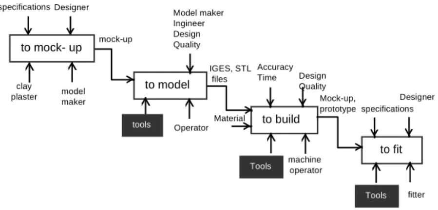
The translation of the rapid prototyping process in terms of function will be able to be put in shape on the basis of a SADT model [IGL Technology]. This type of model permits to focus on fluxes of data of the rapid prototyping chain (see figure 10).
Figure 10: Rapid prototyping process for the duplication of an object
to model to build to fit Designer clay plaster model maker mock-up to mock- up Accuracy Time Model maker Ingineer Design Quality tools Operator Design Quality machine operator IGES, STL files Material Mock-up, prototype specifications Designer fitter specifications Tools Tools
In certain cases, the research of solution can be long and difficult. For example, we note currently in the 3D digitizing domain the existence of incomplete synthesis documents that it is necessary to bring up to date. It is essentially due to the rapid progression of technologies: sensors of optimized shape, piloting software offering new functions, computer platform according to the evolution of the PC computers,....
The technological vigil permits to identify technologies susceptible to answer to the need identified by a specific development but also to identify constructors developing solutions to the problem.
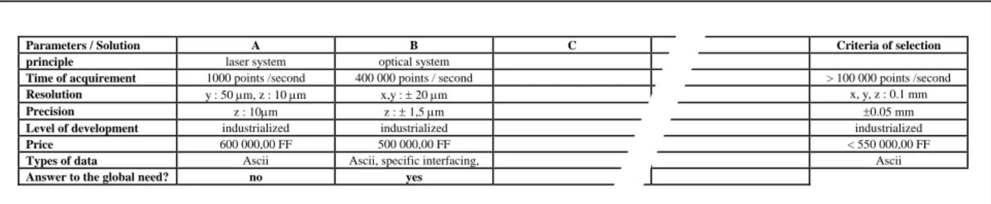
Tools (necessary components to assure functions of the rapid prototyping chain) are determined with the help of the FAST diagram.
The identification of the different parameters of solutions and the definition of criteria selection (established from the functional load notebook) permits to achieve by the project group, a choice first which be qualified as
“director” (see figure 11).
Figure 11: Picture of selection on digitizing systems
Parameters / Solution A B C Criteria of selection
principle laser system optical system
Time of acquirement 1000 points /second 400 000 points / second > 100 000 points /second
Resolution y : 50 μm, z : 10 μm x,y : ± 20 μm x, y, z : 0.1 mm
Precision z : 10μm z : ± 1,5 μm ±0.05 mm
Level of development industrialized industrialized industrialized
Price 600 000,00 FF 500 000,00 FF < 550 000,00 FF
Types of data Ascii Ascii, specific interfacing, Ascii
Answer to the global need? no yes
Each solution is translated in the form of a technical card presenting the constructor (historic of the society, business number, credential,...), the technology employed (description,...), the technical parameters, the various functions filled by the device, its advantages and its inconveniences, its cost, the type of maintenance proposed,....
A the end of this work, a meeting of the group project permits to achieve choices of solutions consigned in a technical and financial orientation file.
Phase 3: Research of process scripts
This stage is crucial for the success of the project. It conssists in organizing and optimizing the different retained solutions in order to propose several scenarios. It is important that this phase is achieved in a multi-disciplinary structure where each actor / user has the possibility to propose his points of view and his wishes.
Research will take place under the shape of an arborescence (see figure 12):
Figure 12: different foreseeable solution Scripts
3D Sensor A 3D Sensor B 3D Sensor C
R.of S. 1 R.of S. 2
CAM 1 CAM 2
FFM 1 FFM 2
Solution A Solution B Solution C
To this level of study, one can evaluate all the importance of the technical cards of solutions. These one permits to ascertain transfers of data flux. They are completed by criteria of assessment permitting to judge the relevance of the architecture proposed.
Propositions of scripts can be written with the SADT model which permits to make a downward and modular description. Every board is associated to a solution in the script. This mode of representation puts in obviousness fluxes of data of the rapid prototyping chain (to see Figure 12).
Our experience shows us that some scripts can be evacuated on criteria of cost, but also in terms of strategic orientation.
As an example, a « A » society uses a CAD software. Its constructor is about to launch on the market a software specialized in digital surfaces building and proposes it to the « A » society with a price challenging all competition because of its customer's importance for its turnover. Nevertheless, after assessment, one can quote that this solution answers minus well than the initially foreseen competitor software. Therefore, the choice of the software depends on the strategy of enterprise knowing that it can put off a proposed script.
Phase 4: Validation of scripts
This phase has for objective to validate, in a first stage, the definition of the rapid prototyping chain; in a second stage the interpretation of the need. The assessment and the retained script comparison are achieved on a concrete case with the future users, constructors, and the group of the project. This case will be to the previously carefully chosen in order to represent the various difficulties to which the enterprise is confronted daily.
Results of assessments are regrouped in a picture permitting to define profiles of materials tested ( see figure 13)
Figure 13: Picture of solution assessment
3D Digitizing system Solution A Solution B Solution C
Criteria of assessment
Faculty to raise different states of surFigure 3 2 1
Operation of calibration and standardization 3 3 1
Digitizing of pieces 3 2 1
Time of acquirement and time of treatment 3 2 1
Graphic information return 3 3 1
Filtering of data 3 3 1
Ergonomics of the software 3 3 1
Evolution of the technology and the software 3 2 1
Notation:
Divergence with regard to the criteria / means-insufficient 1
Light divergence with regard to the criteria / Well 2
Respect of the criteria / Very well 3
The definitive choice is achieved by the whole of actors of the project group and is consigned in a final file.
3.1.2 Example of application on an industrial case
An electronic society asked to the CPN Laboratory to achieve a survey of feasibility on the integration of a rapid prototyping chain within its mechanical research department. Its main activity is the design and the manufacture of telephones (terminal and portable).
The goal of this survey aims at reducing times of development and launch on the market in order to renew ranges of products, to improve the quality of studies and products, to answer to the to needs of the market more quickly: design, ergonomics, functions,... This society already cleared the doorstep of the numeric: the plan paper of definition 2D disappeared; thedigital model became the common reference. Nevertheless, designers
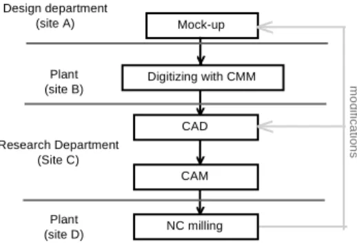
It wishes in the previously described setting, to optimize its digital chain permitting the passage of the physical object to the digital mock up. The present process is basically presented on the figure 14.
Figure 14: the society process
Mock-up Digitizing with CMM CAD CAM NC milling m o di fi c a ti on s Design department (site A) Plant (site B) Research Department (Site C) Plant (site D)
Inconveniences of the present process are next one:
- the digitizing operation is achieved on a Coordinate Measuring Machine on a site of production : this one proves out to be too long (more than 12 hours). Besides, the research department is confronted to the availability of the machine: time limits of waiting can reach several days.
- the rebuilding of surfaces is done on a CAD software. In case of modification, iterative can be difficult and too long. According to the dexterity of operators, a modification can last up to five days.
- the software of CAM (5 axes) is complicated and is difficult to program. It can require several days. Besides, for the machining of similar shapes, it is impossible to use the existing programme manufacturing. - the machining of models is achieved on another site of production. The weak availability of machining machines delays projects.
Therefore, the society intends to acquire: - a 3D digitizing system,
- a specialized software in the modeling of surfaces, - a new solution of machining programming, - a rapid machining center.
The whole of tools must be installed in the local of the research departement. This digital chain should be perfectly compatible with the existing tools (the reliable data transfer to 100%).
The rapid prototyping chain recommended by the society is the following (figure 15):
Figure 15: rapid prototyping Chain recommended by the society
Mock-up Digitizing system Reconstruction of surfaces CAD CAM NC milling m o di fi c a ti on s
Its choice of the process of realization can not be put back in reason:
This society exercises since several years techniques of rapid manufacturing by layers. The validation of functions is made on the representative functional models; the stake to disposition of a model to the tool design department permits to help him in the study and the realization of the mold. The choice to manufacture models by machining is a constraint imposed by designating it : contrarily to processes of manufacture by layers, the
machining doesn't require a manual finish. Thus, the designer can better evaluate the quality of the digital definition: reflections allows to discover mistakes of shapes. Shortcomings to the level of surfaces, points of tangencies, adjustings,... appear indeed.
Translation of the need
The rapid prototyping chain must allow to the research department to optimize the existing digital chain (to see Figure 14) permitting the passage of model design toward the digital model. This chain must integrate the fast realization of the digital model.
The engineers of the research department permitted to put in obviouness the necessity to integrate the function of modification of shapes by the system.
Indeed, modifications of shapes on the software of CAD can prove out to be long and difficult; to take in amount a modification during the time of the surfaces reconstruction can be a gain of time no negligible.
Research of solutions
The survey of solutions adopted by other enterprises or similar domains are good tracks to start the research of solutions. We will be able to give the example of the domain of the conception of jewelries whose objective is the duplication of models by techniques of rapid prototyping [SUR 96].
The value analysis permitted us to define the necessary tools and to confirm the first approach of the society. Nevertheless we could have identified and validated new solutions to which the society had not thought:
- The society orientated itself initially towards laser processes digitizing. The gait that we propose allows to consider all possible solutions. Therefore, we have propose to this society processes of acquirement of shapes based on the optic technology perfectly filling the required features.
- Some digitizing systems offer the possibility to convert clouds of points into triangulated STL model. By this way, while transferring the file directly to the software of programming (accepting this type of format), it is possible to duplicate mock-up design quickly (achieved to the hand). Therefore, the designer has got many models all identical and can propose for each one different solutions (modified by hand, shapes, color,....) and can present them to the different actors of the product design. Besides, one preserves the model evolution, permitting a possible return in rear. The utilization of the reconstruction of surfaces intervenes for the construction of a mathematical surfaces model (digital mock-up) from definite mock-up. This pragmatic approach allows to make a gain in time, to give a chronological account of the study, an availability minimum for the operator of the software.
Figure 16: new process that we proposed
Mock-up Digitizing system Reconstruction of surfaces CAD CAM NC milling m o d ifi c a ti on s Mock-up Digitizing system Reconstruction of surfaces CAD CAM NC milling m o di fi c a ti on s Research of scripts
Example of choice criteria for the composition of a script between the tool of reconstruction of surfaces software and 3D digitizing systems :
According to the technology employe, systems of acquirement of 3D shapes propose two types of files: of the neat point clouds either disorganized. Some reconstruction of surfaces software only accept the first type of file (neat). Therefore, the operator of the software must treat wholes of clouds of points (disorganized) in order to give back them exploitable by the software. This operation of a variable length (sometimes several hours) is an useless time loss: one can consider that the work of surface reconstruction have not already start. In the script design, we avoid to put in such solution correspondence if this one is not automated.
The criteria of assessment associated to this problem will be expressed in the following manner:
Treatment of points: Every introverted point file should be exploitable without specific operation of type: cleaning of the redundant points, creation of subgroups of points,.... This operation should be entirely automated.
Figure 17: Examples of possible script
ATOS KREON
Surfacer
POWERMILL WORK NC
CHARLY ROBOT TECH SOFT ICEM Surf Mock-up Form manufacturing Digital model Reverse engineering Physical model Validation of scripts
Every constructor is warned of assessment conditions (length of the test,...). He must ascertain the working order of his devices and the presence of a specialized operator able to treat the industrial case presented the same day. The result of this investigation is presented under the forms of a SADT diagram on the figure 18.
The final choice is: the ATOS system of the GOM society, the SURFACER software (ImageWare), the software of programming of POWERMILL machining of Delcam, and the center of machining proposed by the society CHARLY ROBOT.
NC operator specification, modification specified to mock-up to scan To reconstruct To modify to programme clay plaster model maker Designer Operator Opérateurs CAD operator Atos Surfacer Atos Surfacer CAD CAM operator Powermill ISO file IGES files IGES, STL files IG E S , S T L fi le s IGES ASCII
files specificationsmodifications
Designer Engineers Designer Design quality quality specifications specifications To build Operator Designer specifications CAD Designer specifications to machine Material Charly Robot
Conclusion on the presented case
The utilization of this method in the setting of the study of the society has been validated. It allowed to define a homogeneous numeric chain answering to the expressed need and perfectly integrating in the product development process existing. The utilization of such a rapid prototyping chain allows to reduce the time cycle of about 30%. Several factors allow this result:
• restraint of the availability of the digitizing system and the rapid machining center (location within the research department),
• of the effective tools: - faster digitizing operation,
- software of specific surface reconstruction,
- possibility to use the existing machining ranges in the CAM software,
- the center of machinings does not require an operator's presence during the night.
The designer can verify it quickly that the numeric definitions of products are perfectly compliant to mock-up. The speed of the digital chain proposed allows to explore and to validate different solutions
4. Conclusion
In this article we have shown the interest of using rapid prototyping techniques and technologies in a more and more complex product design environment.
Facing the evolution and diversity of the proposed tools, we recomand the used of an assistance step to product design of a rapid prototyping process from our industrial experience.
As the need of a firm are different, we propose not to consider the rapid prototyping chain as a single tool assembling, but as a whale of functions to satisfy. The tools research only intervene in a second time. By this way, the designer is able togather all the necessary data to choose and to avaluate tools to design a rapid prototyping process responding to the need.
This method lies within an increasing of the realibility and quality of product development process.
5. Bibliography
[ADI 97] ADIT : AGENCE POUR LA DIFFUSION DE L’INFORMATION TECHNOLOGIQUE, L’Annuaire
des Technologies Clés, Ministère de l’Economie, des Finances et de l’Industrie, Secrétariat d’Etat à l’Industrie,
[AOU 90] AOUSSAT Amézaine, La pertinence en innovation : nécessité d’une approche plurielle,Thèse de Doctorat, ENSAM 1990.
[BAR 95] BARLIER C. et coauteurs, Conception en Mécanique Industrielle. Partie 6 : Maîtriser les outils de
prototypage rapide, Collection “Référentiels”, Editions DUNOD (1995)
[BAR 93] BARALDI U., DORMAL T., VADE MECUM des technologies du prototypage rapide, CRIF, Liège, 1993.
[BAR 98] BARLIER C. et CUNIN, Le rôle des outils de prototypage rapide et d’outillage rapide en
conception de produits, Rencontres SIA/ DECLIC AUTO 98, 1998
[BEA 96] BEAUFILS Ph., La rétroconception à votre portée, Industries et Techniques, N°768- février 1996 [BEA 95] BEAUFILS Ph; , La numérisation de formes tridimensionnelles, Industries et Techniques, N°756- janvier 1995
[BER 97] BERNARD Alain, Développement rapide de produit, 5ème colloque sur la Conceptio mécanique Intégrée, avril 1997.
[BOU 94] BOURDICHON Patrick, L’ingénierie simultanée et la gestion d’informations, Editions Hermès, 1994 [BOU 96] BOUYSSIE Jean-François, Modélisation des déficits osseux par stéréolithographie, Etude sur la
précision dimensionnelle et surfacique du procédé, Thèse de Doctorat, Université Paul Sabatier de Toulouse,
1996
[BOUR 96] BOURELL DL, BEAMAN J.J., BARLOW J.W., CRAWFORD R.H., Current and Future trebds in
solid free form fabrication, SPIE - The International Society for Optical Engineering, Vol. 2910, 18-19 nov.
1996
[CAR 92] CARTER Donald E. & STIWEL BAKER Barbara, CE Concurrent Engineering, The Product
Development Environment for the 1990s,Addison-Wesley Publishing Compagny, INC, p.175, 1992
[DOL 94] DOLENC A., Overview of Rapid Prototyping Technlogies in Manufacturing,Helsinki University of Technologie, National Technical Information Service, VA. 22161, 1994
[HOU 97] HOUDELLEBECQ Claude, La guerre du temps ou la contribution de l’informatique technique et scientifique à la réduction des délais, Lettre de l’Association Française Micado, Innovapresse Création & Edition, N°19,Novembre/Décembre 1997.
[HUM 97] HUMBERT, Les différentes technologies de numérisation et capteurs associés,Numérisation 3D, Actes des conférences, 1997.
[JAG 94] JAGOU , Concurrent Engineering,Editions Hermes, 1994
[JAC 95] JACOBS Paul F., Enhanced Stereolithography Patterns for Investement Casting and Rapid Tooling,
in Actes 4ème Assises Européennes du Prototypage Rapide, 4 & 5 octobre 1995
[LEC 92] LE COQ Marc, Approche Intégrative en Conception de Produits, Thèse de Doctorat, ENSAM, 1992. [MAS 98] MASCLE Christian, CARON Marie Christine, FORTIN Clément, Méthodologie d’évaluation de step
pour les entreprises,2ème Conférence Internationale sur la conception et la fabrication intégrées en Mécanique,
IDMME’98, Proceeding-Volume IV, 1998.
[MIC 95] MICADO, Le prototypage rapide, Les cahiers techniques de Micado,Juin 1995.
[NON 93] NONNENMACHER François, La stéréolithographie en question - Rapport sur l’état du prototypage
rapide en 1993, 1993.
[PET 87] PETITDEMANGE Claude, Créer et Développer vos produits,Analyse de la valeur, Edition AFNOR 1987
[SUR 96] SURET S., BERNARD A. , BOCQUET J.C. , Using rapid prototyping for new products development
:application to jewelry design, SPIE - The International Society for Optical Engineering, Vol. 2910, 18-19 nov.
1996
[YAN 97] YANNOU Bernard, Analyse Fonctionnelle et Analyse de la Valeur, Actes du 5ème Colloque sur la Conception Mécanique Intégrée, Primeca, 2&4 avril 1997
![Figure 2: The computer model of the Competitor Engineering [JAG 94]](https://thumb-eu.123doks.com/thumbv2/123doknet/7272336.206564/3.892.358.595.475.619/figure-computer-model-competitor-engineering-jag.webp)
![Figure 3: Types of model and prototype achieved by rapid prototyping during the process of product development according to Baraldi [BAR 93]](https://thumb-eu.123doks.com/thumbv2/123doknet/7272336.206564/4.892.226.730.548.829/figure-prototype-achieved-prototyping-process-development-according-baraldi.webp)