Synthesis of Monodisperse Fluorinated Silica Nanoparticles and Their Superhydrophobic Thin Films
Jean-Denis Brassard†‡, D. K. Sarkar*‡, and Jean Perron†
†Anti-icing Materials International Laboratory (AMIL) and ‡Centre Universitaire de
Recherche sur l′Aluminium (CURAL), Université du Québec à Chicoutimi, 555 Boulevard de l′Université, Chicoutimi, Québec, Canada, G7H 2B1
ACS Appl. Mater. Interfaces, 2011, 3 (9), pp 3583–3588 DOI: 10.1021/am2007917
Publication Date (Web): September 8, 2011
Abstract :
Monodispersive silica nanoparticles have been synthesized via the Stöber process and further functionalized by adding fluorinated groups using fluoroalkylsilane in an ethanolic solution. In this process, six different sizes of fluorinated silica nanoparticles of varying diameter from 40 to 300 nm are prepared and used to deposit thin films on aluminum alloy surfaces using spin coating processes. The functionalization of silica nanoparticles by fluorinated group has been confirmed by the presence C–F bonds along with Si–O–Si bonds in the thin films as analyzed by Fourier transform infrared spectroscopy (FTIR). The surface roughnesses as well as the water contact angles of the fluorinated silica nanoparticle containing thin films are found to be increased with the increase of the diameter of the synthesized fluorinated silica nanoparticles. The thin films prepared using the fluorinated silica nanoparticles having a critical size of 119 ± 12 nm provide a surface roughness of ∼0.697 µm rendering the surfaces superhydrophobic with a water contact angle of 151 ± 4°. The roughness as well as the water contact angle increases on the superhydrophobic thin films with further increase in the size of the fluorinated silica nanoparticles in the films.
Keywords : sol−gel process; fluorinated silica nanoparticles; functionalization of nanoparticles; superhydrophobicity; fluoroalkylsilane; aluminum; water contact angle; FTIR; scanning electron microscopy; profilometry
Introduction
After a rainy day, shining water drops keeping a nearly perfect spherical shape on certain leaves is one of the most beautiful wonders of nature. This natural phenomenon is observed not only on plants, it is also observed on the surfaces of several living creatures on the earth. This nonwetting phenomenon is well-understood on lotus leaves and it is considered as the basis of the studies of superhydrophobicity.(1-4) The
microscopic observation of the surface of the lotus leaves using scanning electron microscope (SEM) show the coexistence of combined micro and nano structures in addition with a hydrophobic wax component. The existence of this binary structure on the surface of the lotus leaves allows a large amount of air entrapment and thus consequently reduces the contact area of water on it. The presence of low surface energy waxy components with reduced affinity to water together leads to the
superhydrophobic properties. Cassie and Baxter(5) as well as Wenzel(6) proposed two mathematical models to explain the wetting phenomena on rough surfaces that leads to superhydrophobic properties. By definition, superhydrophobic surfaces are characterized by a water contact angle value ≥150° with the resultant rolling off of water drops from the surfaces.(7) Because of its water-repellent property, superhydrophobic surfaces have several emerging applications in a large number of fields such as self-cleaning-fabrics, anticorrosive industrials parts and even surface drag reduction to reduce energy
consumption of transport systems.(8-10) Different techniques such as chemical etching, chemical bath deposition, electrodeposition, photolithography, plasma processes, etc. are currently being used to create superhydrophobic surfaces.(7, 8, 11-13) The most significant barrier caused by these techniques is the difficulty of fabrication of large scale depositions in a cost-effective way. Sol–gel techniques together with spray coatings or commercial paintbrush coatings might be one approach to overcome such draw back.(13)
In this study, silica nanoparticles with varying sizes were prepared in the laboratory using standard Stöber process and further functionalized with fluoroalkylsilane (FAS17) in an ethanolic solution to obtain fluorinated silica nanoparticles. These fluorinated silica nanoparticles dispersed solutions were spin-coated on aluminum alloy substrates to obtain superhydrophobic thin films.
Experimental Section
The solutions containing fluorinated silica nanoparticles of varying sizes are prepared in the laboratory using standard Stöber process.(14) Initially, at a hot plate temperature of 50 °C, ethanol and ammonium hydroxide (NH4OH) were mixed in a beaker using a magnetic stir bar. While stirring, a solution of tetraethoxysilane or TEOS ((Si(OC2H5)4) is added drop by drop to the mixed solution. The transparent mixed solution turns opaque, confirming the formation of silica nanoparticles.(15-17) The synthesized silica nanoparticles are further funtionalized in an ethanolilc fluoroalkylsilane or FAS17 (C16H19F17O3Si) solution. The experimental details are presented in Table 1. The AA-6061 aluminum alloy and silicon substrates were coated with the fluorinated silica nanoparticles by spin-coating processes. The nanoparticles coated films were dried at a 70 °C on a hot plate to allow the ethanol and excess water to evaporate from the films. Fourier Transform Infrared spectroscope (FTIR) (Perkins Elmer Spectrum one) were used to evaluate the atomic bonding in the films. The films were also analyzed using a
high-resolution field emission gun scanning electron microscope (FEGSEM: Hitachi SU-70) for morphological analysis. The wetting properties of the prepared and functionalized nanoparticle coated aluminum alloy surfaces were performed using the contact angle measurements (VCA optima). The surface roughnesses of the films were measured using an optical profilometer (MicroXAM-100 HR 3D surface profilometer).
Results and Discussion
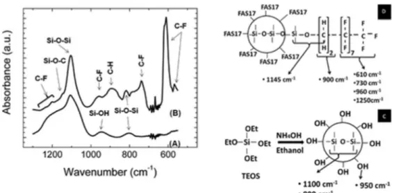
FTIR analyses were carried out on the thin films deposited on silicon substrates to develop an understanding of the interatomic bonding in the fluorinated silica nanoparticles. Spectra A and B in Figure 1 show the FTIR spectra of the thin films prepared with silica nanoparticles and fluorinated silica nanoparticles, respectively. The spectrum in Figure 1A shows only three significant peaks of silica. The strongest peak is at 1100 cm–1 with an accompanying asymmetric broad shoulder extended until 1250 cm–1. This is due to the asymmetric stretching vibration of Si–O–Si bonds in the silica nanoparticles in the thin films.(18-21) Another small peak appearing around at 800 cm–1 is associated with the bending mode of Si–O–Si bonds. A weak absorption peak, as compared to the peak of Si–O–Si at 1100 cm–1, appears at 950 cm–1 due the presence of Si–OH bonds.(22) Figure 1c shows the reaction and the model of the formation of spherical oligomerization of TEOS molecules in the ethanol solutions in the presence of NH4OH catalyst. The vibrational bonds of Si–O–Si with OH and their corresponding wavenumbers are also presented in the model. The FTIR spectra of the films prepared using fluorinated silica nanoparticles shown Figure 1 B reveals distinctly the emergence of some additional new peaks as compared to those prepared using only silica
nanoparticles shown in Figure 1 A. Two tiny peaks superimposed between 1130 and 1250 cm–1 on the left shoulder of the Si–O–Si peak at 1100 cm–1 are due to the stretching vibration of C–F bonds anticipated because of the fluorination of the silica nanoparticles by the FAS17 molecules.(23-25)
Figure 1. FTIR spectra of the thin films prepared with (A) silica nanoparticles, and (B) fluorinated silica nanoparticles. (C) Reaction mechanism and the schematic model of the formation of silica nanoparticles as well as the vibrational bonds and the corresponding wavenumbers, (D) the functionalization of silica nanoparticles by FAS17 molecules is shown as well as the vibrational bonds and the corresponding wavenumbers.
The existence of C–F bonds in the form of CF, CF2, or CF3 are also located at 575, 610, 730, 960 cm–1.(24) A reasonably broad peak around 900 cm–1 is assigned to the C–H bonds, arising from FAS17 molecules.(19, 26) A peak approximately at 1145 cm–1 is due to the Si–O–C bond that arises due to the link between FAS17 molecules and the silica nanoparticles(26) as shown in our model in Figure 1D. The presence of additional new peaks arising from the fluorinated functional groups present in the films confirms that the nanoparticles of silica are functionalized by fluorine from the FAS17 molecules. Figures 1D shows the schematic model of the functionalization and the formation of fluorinated silica nanoparticles as decoded from the FTIR spectrum of Figure 1B. Every H atom from each OH bond around the silica nanoparticles of Figure 1C is replaced by a Si atom of the FAS17 molecule as presented in the model of Figure 1D. The new
vibrational bonds of Si–O–C, C–H, and C–F and their corresponding wavenumbers are also presented in the figure.
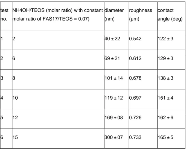
Table 1. Chemicals for the Preparation of Fluorinated Silica Nanoparticles, Their
Diameter, The Roughness of the Prepared Thin Films and the Water Contact Angles on the Films
test no.
NH4OH/TEOS (molar ratio) with constant molar ratio of FAS17/TEOS = 0.07)
diameter (nm) roughness (µm) contact angle (deg) 1 2 40 ± 22 0.542 122 ± 3 2 6 69 ± 21 0.612 129 ± 3 3 8 101 ± 14 0.678 138 ± 3 4 10 119 ± 12 0.697 151 ± 4 5 12 169 ± 08 0.726 162 ± 6 6 15 300 ± 07 0.733 165 ± 5
Table 1 provides the different NH4OH/TEOS ratios used in the preparation of the thin films of fluorinated silica nanoparticles with a constant FAS17/TEOS molar ratio of 0.07 using a standard Stöber process(27) to prepare silica nanoparticles followed by
modification using FAS17 molecules. Table 1 also summarizes the information on the size of the prepared nanoparticles that variy from 40 to 300 nm with the increase in the molar ratio of from 2 to 15. The size of the silica nanoparticles are found to increase with the increase in the molar ratio of NH4OH/TEOS. Also, it is clear from the Table 1 that the roughness and water contact angles increases with increase in the sizes of the
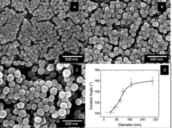
fluorinated silica nanoparticles in the films. Figure 2A–C shows the SEM images of three different films prepared from three different sizes of monodispersive fluorinated silica nanoparticles on aluminum alloy surfaces. Figure 2A shows that the size of the
nanoparticles prepared with the molar ratio of NH4OH/TEOS of 6 is 69 ± 22 nm. Figure 2B shows that the particles sizes increased to 119 ± 12 nm with the increase of NH4OH to a NH4OH/TEOS molar ratio of 10. Subsequently, Figure 2C shows that the size of the nanoparticles are further increased to 169 ± 8 nm with the increase in molar ratio of NH4OH/TEOS to 12. Nozawa et al.(25) obtained 110 ± 20 nm silica nanoparticles using
the Stöber process at a NH4OH/TEOS molar ratio of 10; however, in our study, the size of the nanoparticles obtained under tha same conditions are ∼10 nm larger (119 ± 12 nm) than that obtained by Nozawa et al. The larger size in our case is attributed to the presence of an outer shell of fluorinated silane bonded around the silica spheres as a result of fluorination using FAS17 molecules as presented in the schematic model shown in Figure 1 D.
Figure 2. SEM images of fluorinated silica nanoparticles of sizes (A) 69 ± 22 nm, (B) 119 ± 12 nm, and (C) 169 ± 8 nm, and (D) the water contact angles on the thin films
prepared from fluorinated silica nanoparticles of varying sizes.
Figure 2D shows the variation of water contact angle with the size of the fluorinated silica nanoparticles in the thin films. Figure 2D shows that the water contact angles of the films prepared with the fluorinated silica nanoparticles of sizes 40 ± 22 and 69 ± 21 nm are found to be 122 ± 3 and 129 ± 3°, respectively. These values are slightly higher than the contact angle value of 108° obtained on FAS17 passivated flat glass
surface.(28) The slight increase, although not great, in the contact angle values can be attributed to the presence of low surface energy fluorinated species arising from the functionalization of the silica nanoparticles. We have observed that the water contact angle reached 138 ± 3° on the surface of the thin films having fluorinated silica nanoparticles of larger size of 101 ± 14 nm. Superhydrophobicity is defined herein as
more than 150° contact angle. This experimental series showed superhydrophobicity (151 ± 4°) is reached on the films having fluorinated silica nanoparticles of critical size of 119 ± 12 nm. The water contact angle increased to 162 ± 6° by increasing the size of the fluorinated silica nanoparticles to 169 ± 8 nm in the films. As the size of the fluorinated silica nanoparticles increased further to 300 ± 7 nm, the water contact angle further increased to 165 ± 5°. Yang et al. show a similar tendency on the variation of water contact angles of −CH3-terminated (using methyltriethoxysilane) silica nanoparticles.(16) These authors reported a water contact angle of 135° on the surface of the films having −CH3 terminated silica nanoparticles of sizes between 30 and 50 nm. In their study, the critical size of the −CH3 terminated silica nanoparticles to obtain superhydrophobic films was reported to be 200 nm. Furthermore, their study shows increasing the size of the −CH3 terminated silica nanoparticles to 300 nm did not further influence the water contact angle. Cao et al. reported the behavior of water contact angle of the thin polymer films prepared using organosilane-modified silica particles of various diameters (20 nm, 50 nm, 100 nm, 1 µm, 10 µm, and 20 µm).(23) These authors reported a water contact angle greater than 150° for the polymer films incorporated with organosilane-modified silica particles with an initial size of only 20 nm. With an increase in their particle sizes to 50 and 100 nm, the contact angle increased to ∼158° and remained similar in both cases. However, with a further increase in their particle size to more than 100 nm, they reported a decrease in contact angles. However, these authors did not show
microscopic evidence to confirm the size of their organosilane-modified silica particles in the films. The sizes of their ogranosilane-modified silica nanoparticles in their films might actually be much be larger than reported leading to sufficient surface roughness to provide high water contact angles. Nevertheless, our observation of increase in water contact angle with an increase in the functionalized silica nanoparticles is consistent with the observations by Yan et al. as well as Cao et al. Such an increase in the water
contact angle with the increase of the size of the spherical nanoparticles could be
attributed to a large amount of air entrapment between the particles forming a composite microstructure of the solid particles and the air that reduces the effective contact area of water from the surfaces.(29)
The SEM images of Figure 2 reveal the presence of the spherical silica nanoparticles distributed randomly on the surfaces of thin films achieved by spin-coating process. The images also demonstrate that nanoparticles also have a tendency to be agglomerated to form clusters, hence resulting in a rough morphology. Evidently the size of the
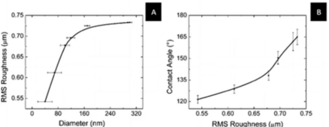
nanoparticles and their clusters has an impact on the surface roughness. Figure 3A shows the variation in the surface roughness influenced by the size of the deposited functionalized silica nanoparticles. Figure 3B shows the variations of the water contact angles on these surfaces with their surface roughnesses. It has been previously described in Figure 1 D that the contact angles greatly vary with the size of the
nanoparticles. A correlation between the roughness and the particle size as well as the contact angle and roughness has been found as depicted by Figure 3A,B. The surface roughness of the film prepared with 40 ± 22 nm fluorinated silica nanoparticles is found to be ∼0.542 µm and is very similar to that obtained on the as-received aluminum alloy surface (∼0.535 µm). However, a slightly higher water contact angle of 122 ± 3°
attributed to the combined presence of fluorinated species was obtained on this surface as compared to only ∼108° on the as-receive aluminum alloy surface. The surface roughness increased to ∼0.613 µm on the thin films prepared with the fluorinated silica nanoparticles of a larger size of 69 ± 22 nm providing a higher water contact angle of 129 ± 3°. Similarly, the thin films having the fluorinated silica nanoparticles of size 101 ± 14 nm results in a slightly higher surface roughness of ∼0.678 µm with increased water contact of 138 ± 3°. A critical surface roughness of ∼0.697 µm was obtained when the thin films were prepared using fluorinated silica nanoparticles of larger size of 119 ± 12 nm in the films which led to superhydrophobic surfaces providing a higher water contact angle of 151 ± 4°. The increase of the size of the nanoparticles in the films to 169 ± 8 nm results in a higher surface roughness of ∼0.726 µm enhancing the water contact angle to as much as 162 ± 6°. It is to mention that the thickness of our films is approximately 1.0 µm that provides roughnesses of a fraction of a micrometer. We have previously reported as well as patented that the thickness of the sol–gel-derived silicate films reduced with the dilution of the sol.(30, 31) However, in the present study we have not work out on the effect of dilution on thickness. Further work might be interesting to study the variation of thickness and roughness as well as the contact angle with the dilution of the fluorinated silica nanoparticles dispersed solution as we have prepared.
Figure 3. (A) Root-mean-square (rms) roughness of the surfaces of the thin films prepared from the various sizes of the fluorinated silica nanoparticles and (B) the variation in the water contact angle with the roughness.
With a further increase of the fluorinated silica nanoparticles size to 300 ± 7 nm on the films, the surface roughness slightly increased to ∼0.733 µm and provided a water contact angle of 165 ± 5°. From these observations, it can be seen that a critical nanoparticle size of 119 ± 12 nm was necessary to obtain a roughness of ∼0.697 µm, which is critical to obtain superhydrophobic surfaces. Cho et al.(32) show that the surface roughness of the films prepared with spherical nanoparticles increases linearly, as initially encountered in Figure 3A. Rawal et al.(33) also show that the water contact angle increases with the increase of the roughness. All these values and observations indicate that with increasing sizes of the functionalized silica nanoparticles in the thin films deposited on the aluminum alloy surfaces, the surface roughnesses increases with an increase in the water contact angle. Higher surface roughness allows large amount of air entrapment to reduce the contact area of the water drops with the surface. In
addition, the higher surface roughness may also expose higher surface area with the possibility of increasing the density of the fluorinated species on the particles’ surface thus forming as a shell around the silica nanoparticles. Both effects of roughness and low surface energy molecules on the deposited thin films results in higher water contact angles and hence superhdyrophobicity.
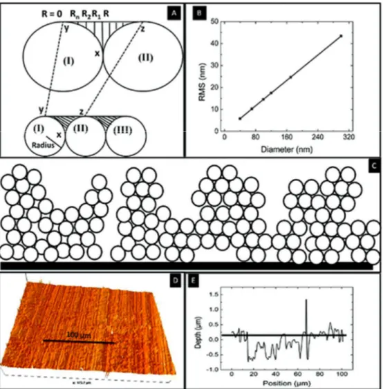
A model has been presented in Figure 4 to explain the increase of roughness with the increase of the size of the particles. Figure 4A shows a schematic of a one-dimensional growth of spherical particles on a surface. In this model we consider these particles as perfect circles. The shaded areas between the circles are responsible for providing roughness to the films due to the spherical form of particles on the surface. The Figure 4A (top) also shows a shaded area between the two circles. A horizontal line (tangent for
both the circles) is drawn on the top of the two circles. This shaded area is separated into two parts each associated with a circle. Considering the left circle and the shaded part associated with it, we can calculate the roughness arising from that part. Several vertical lines have been drawn from the horizontal line as shown in figure 4. It is clear from the figure that the lengths of the vertical lines vary between R and 0 from right to left. In this figure, R is the radius of the circle (or sphere). In our calculation, the left-vertical length reduces by one unit from the adjacent right-left-vertical length for each step. Therefore, we generate several vertical lengths, Ri, between R and 0. The generated verticals lengths are R, R-1, R-2, ..., 0 and their average length, R̅, is R/2. Utilizing the statistical analysis, as shown in eq 1, we have determined the fluctuation of root-mean-square (rms) of these numbers. This calculated rms is considered as the roughness of the surface in our
model.
Using this calculation method we have derived the roughness of all surfaces based upon their varying experimentally measured particle sizes. The Figure 4B shows a linear relation between the roughness and the diameter of the particles. The value of the calculated roughness is much smaller than the value obtained experimentally (Figure 3A). Figure 4C shows a more realistic model surface that composed of particles, clusters and cracks on the films prepared with spin-coating process using the spherical
nanoparticles. This model surface is comparable with the SEM images of Figure 2A–C those composed of agglomerated spherical nanoparticles as well as several cracks. Therefore, the measured roughness of the prepared thin film surfaces is much higher than on our one-dimensional model of spherical particles dispersed thin films surfaces.
Figure 4. (A)Schematic model of one-dimensional growth of perfectly spherical particles on a surface. The shaded areas between particles I, II, and III are responsible for the entrapment of air as well as the roughness. Particles I and II have been redrawn in larger diameters on the top part of A and several vertical lines are drawn with varying length from R to 0. (B) Plot of the calculated roughness with the increase of the diameter of the spherical particles as in A. (C) More realistic model of our thin films. (D) 3D image as obtained from the optical profilometry. (E) 1D cross-section of image D.
It has to be emphasized that the value of the rms roughness is associated with the area between two circles (contour XYZ). It is obvious that the area of this region also
increases with the increase of the particle size. Accordingly to Cassie–Baxter equation for an air trapped rough surface: cos(θ′) = f1cos(θ1) – f2cos(θ2), where f1 and f2 are, respectively, fraction of solid and fraction of air, similarly, and θ1 and θ2 are,
respectively, contact angles of water with solid and air. Assuming that f1 = 1 – f2, and θ2 is 180° in air, this equation can be rewritten in form of cos(θ′) = (1 – f2)cos(θ1) – f2. It is
evident from this equation that the larger the fraction of air (f2), the greater the angle of contact. According to our experimental results and mathematical calculation, thin films with large particles provide higher roughness and higher area of air entrapment (f2), and thus an increase in surface roughness and contact angle with the increase in the size of the fluorinated silica nanoparticles in our films. Similar observation has been reported by Synytska et al. on polymer particles dispersed thin films.(34)
The profilometry data has been used to determine the faction of solid to explain the experimentally observed contact angle. Figure 4D shows a three-dimensional image of the thin films obtained by the optical profilometry technique; the thin films were prepared using 119 ± 12 nm fluorinated silica nanoparticles (SEM image of the film is shown in Figure 2B). Obviously, the resolution of this image, due to light source, is much lower than the SEM image. Figure 4E shows one-dimensional cross-section image of Figure 4D. A line parallel to x-axis has been drawn in Figure 4D to show the position of the water drop on the surface. The fraction of the solid (f1 in the Cassie–Baxter model) has been calculated as the sum of the lengths of the lines between the individual peaks of Figure 4D. Ten cross-sectional data plots have been used to determine the fraction of the solid (f1) and it is found to be 0.18 ± 0.05. This f1 value along with the θ1 value which is considered to be equal to 108° for a smooth FAS17-coated(28) surface has been put in the Cassie–Baxter model to calculate the contact angle. This calculated contact angle is found to be 151 ± 8°, which matches very well with our observed contact angle for the films prepared with 119 ± 12 nm fluorinated silica nanoparticles. Though most of the literatures on superhydrophobic surfaces used the Cassie–Baxter model to explain wetting properties, recently, Lui et al.(35) proposed a mathematical model to explain superhydrophobic phenomenon on high-energy surfaces considering a
sinusoidal shape of a surface. This model has been used by Sahoo et al.(36) to explain their superhydrophobic plasma-enhanced chemical vapor -deposited GaN thin film surface.
We have demonstrated that the sol–gel technique is an appropriate method to prepare fluorinated silica nanoparticles and fabricate superhydrophobic surfaces by spin-coating process. The same fluorinated silica nanoparticles can be used in large scale to prepare superhydrophobic surfaces by spray coating method with the proper control to achieve similar roughness for industrial applications.
Conclusions
Monodispersive spherical fluorinated silica nanoparticles have been prepared by sol–gel processes and used to prepare thin films on flat aluminum and silicon substrates by spin-coating processes. FAS17 molecules are used for the fluorination of the silica nanoparticles. FTIR analysis of the thin films shows the presence of C–F, C–H, and Si– O bonds anticipated from the functionalization of silica nanoparticles by FAS17
molecules. We have observed that the water contact angle as well as the surface
roughness of the thin films increases with the increase of the size of the fluorinated silica nanoparticles. A critical particle size of 119 ± 12 nm of the fluorinated silica nanoparticles was necessary to obtain an optimum surface surface of of 0.697 µm to lead to
superhdyrophobic surfaces with water roll-off properties. With proper experimental conditions same roughness as obtained by spin-coating process can be obtained via spray coating technique for industrial applications of the sol–gel-derived fluorinated silica nanoparticles.
Acknowledgment
The authors thank the Natural Sciences and Engineering Research Council of Canada (NSERC) for the financial support. The authors also thank Mrs. C. Potvin for access of FTIR facilities, Prof. D. Kocaefe for access of the profilometry apparatus at CURAL research centre, and Prof. Z. Zhang at CURAL and Mrs H. Gregoire at NRC-ATC, Chicoutimi, for the SEM analysis. The authors thank Dr. N. Saleema, NRC-ATC, Chicoutimi; as well as Jeff Marshal, senior scientist at PATT Technology, Montreal, for their critical reading of the manuscript.
References
1. Gao, X.; Jiang, L. Nature 2004, 432, 36
2. Huang, J.; Wang, X.; Wang, Z. L. Nano Lett. 2006, 6, 2325 3. Neinhuis, C.; Barthlott, W. Ann. Botan. 1997, 79, 667 4. Zheng, Y.; Gao, X.; Jiang, L. Soft Matter 2007, 3, 178
5. Cassie, A. B. D.; Baxter, S. Trans. Faraday Soc. 1944, 40, 546 6. Wenzel, R. N. Ind. Eng. Chem. 1936, 28, 988
7. Sarkar, D. K.; Saleema, N. Surf. Coat. Technol. 2010, 204, 2483 8. Huang, Y.; Sarkar, D. K.; Chen, X. G. Mater. Lett. 2010, 64, 2722 [CrossRef], [CAS]
9. McHale, G.; Shirtcliffe, N. J.; Evans, C. R.; Newton, M. I. Appl. Phys. Lett. 2009, 94, 6 10. Shirtcliffe, N. J.; McHale, G.; Atherton, S.; Newton, M. I. Adv. Colloid Interface Sci. 2010, 161, 124
11. Saleema, N.; Sarkar, D. K.; Paynter, R. W.; Chen, X. G. ACS Appl. Mater. Interfaces 2010, 2, 2500
12. Sarkar, D. K.; Farzaneh, M. J. Adhes. Sci. Technol. 2009, 23, 1215
13. Fernando Raymond, H.Nanocomposite and Nanostructured Coatings: Recent Advancements. In Nanotechnology Applications in Coatings; ACS Symposium Series; American Chemical Society: Washington, D.C., 2009; p 2.
14. Stöber, W.; Fink, A.; Bohn, E. J. Colloid Interface Sci. 1968, 26, 62
15. Chen, S.-L.; Dong, P.; Yang, G.-H.; Yang, J.-J. Ind. Eng. Chem. Res. 1996, 35, 4487 16. Yang, H.; Pi, P.; Cai, Z.-Q.; Wen, X.; Wang, X.; Cheng, J.; Yang, Z.-r. Appl. Surf. Sci. 2010, 256, 4095
17. Bravo, J.; Zhai, L.; Wu, Z.; Cohen, R. E.; Rubner, M. F. Langmuir 2007, 23, 7293 18. Hozumi, A.; Takai, O. Thin Solid Films 1997, 303, 222
19. Latthe, S. S.; Imai, H.; Ganesan, V.; Rao, A. V. Appl. Surf. Sci. 2009, 256, 217 20. Teshima, K.; Sugimura, H.; Inoue, Y.; Takai, O. Langmuir 2003, 19, 8331 21. Zhao, Y.; Li, M.; Lu, Q.; Shi, Z. Langmuir 2008, 24, 12651
22. Pereira, C.; Alves, C.; Monteiro, A.; Magén, C.; Pereira, A. M.; Ibarra, A.; Ibarra, M. R.; Tavares, P. B.; Araújo, J. P.; Blanco, G.; Pintado, J. M.; Carvalho, A. P.; Pires, J.; Pereira, M. F. R.; Freire, C. ACS Appl. Mater. Interfaces 2011, 3, 2289
23. Cao, L.; Jones, A. K.; Sikka, V. K.; Wu, J.; Gao, D. Langmuir 2009, 25, 12444 24. Hozumi, A.; Takai, O. Appl. Surf. Sci. 1996, 103, 431
25. Nozawa, K.; Gailhanou, H.; Raison, L.; Panizza, P.; Ushiki, H.; Sellier, E.; Delville, J. P.; Delville, M. H. Langmuir 2004, 21, 1516
26. Stuart, B. Infrared Spectroscopy: Fundamentals and Applications; J. Wiley: Chichester, U.K., 2004; p 224.
27. Li, X.-M.; He, T.; Crego-Calama, M.; Reinhoudt, D. N. Langmuir 2008, 24, 8008 28. Li, H.; Wang, X.; Song, Y.; Liu, Y.; Li, Q.; Jiang, L.; Zhu, D. Angew. Chem., Int. Ed. 2001, 40, 1743
29. Carré, A.; Mittal, K. L. Superhydrophobic Surfaces; VSP: Leiden, The Netherlands, 2009; p 495.
30. Sarkar, D. K.; Brassard, D.; Khakani, M. A. E.; Ouellet, L. Thin Solid Films 2007, 515, 4788
31. Khakani, A.; Sarkar, D.; Ouellet, L.; Brassard, D. U.S. patent 7 101 754, 2006. 32. Cho, K. L.; Liaw, I. I.; Wu, A. H. F.; Lamb, R. N. J. Phys. Chem. C 2010, 114, 11228 33. Rawal, S. K.; Chawla, A. K.; Chawla, V.; Jayaganthan, R.; Chandra, R. Mater. Sci. Eng., B 2010, 172, 259
34. Synytska, A.; Ionov, L.; Minko, S.; Motornov, M.; Eichhorn, K.-J.; Stamm, M.; Grundke, K. Polym. Mater. Sci. Eng. 2004, 90, 624
35. Liu, J. L.; Feng, X. Q.; Wang, G.; Yu, S. W. J. Phys.: Condens. Matter 2007, 19, 356002.
36. Sahoo, P.; Dhara, S.; Dash, S.; Raj, B.; Manna, I.; Tyagi, A. K. Appl. Phys. Lett. 2011, 98, 092902.
![[PDF] Cours pdf sur Les modules en Ocaml | Formation informatique](data:image/gif;base64,R0lGODlhAQABAIAAAP///wAAACH5BAEAAAAALAAAAAABAAEAAAICRAEAOw==)