HAL Id: hal-01008965
https://hal.archives-ouvertes.fr/hal-01008965
Submitted on 7 Jan 2020HAL is a multi-disciplinary open access archive for the deposit and dissemination of sci-entific research documents, whether they are pub-lished or not. The documents may come from teaching and research institutions in France or abroad, or from public or private research centers.
L’archive ouverte pluridisciplinaire HAL, est destinée au dépôt et à la diffusion de documents scientifiques de niveau recherche, publiés ou non, émanant des établissements d’enseignement et de recherche français ou étrangers, des laboratoires publics ou privés.
Stress-strain model for FRP-confined concrete columns
under cyclic and seismic loading
C. Desprez, J. Mazars, Panagiotis Kotronis, P. Paultre
To cite this version:
C. Desprez, J. Mazars, Panagiotis Kotronis, P. Paultre. Stress-strain model for FRP-confined con-crete columns under cyclic and seismic loading. 15th World Conference on Earthquake Engineering (15WCEE), Sep 2012, Lisbonne, Portugal. pp.6656-6664. �hal-01008965�
Stress-Strain Model For FRP-Confined
Concrete Columns Under Cyclic
And Seismic Loading
C. Desprez
Université Paris-Est, IFSTTAR, SOA, Paris, France, [email protected]
J. Mazars
Grenoble Institute of Technology, Laboratoire 3S-R, Grenoble, France
P. Kotronis
LUNAM Université, Ecole Centrale de Nantes, Gem, CNRS UMR 6183, France
P. Paultre
CRGP, Université de Sherbrooke, Département de Génie, Canada (Qc)
SUMMARY :
In structural engineering, seismic vulnerability reduction of existing structures is a crucial issue. External reinforcement with fiber-reinforced polymer (FRP) holds interest in achieving this aim. Its use as a retrofitting method is limited, however, for a number of reasons, including the lack of numerical tools for predicting cyclic loading. This paper presents a simplified stress-strain model suitable for monotonic and cycling loading capable of predicting the FRP’s effect on reinforced-concrete columns. The model is inspired by two well-known concrete constitutive laws: one based on damage mechanics (La Borderie’s concrete-damage model, 1991); the other on extensive experimental studies (Eid & Paultre’s confined-concrete model, 2008). Validation is provided using experimental results on reinforced concrete columns subjected to axial and flexural cyclic loading. All the simulations were conducted with multifiber Timoshenko beam elements.
Keywords: FRP; Confined-concrete; Stress-strain model; Cyclic loading; Multifiber beam.
1 INTRODUCTION
Mitigation of the seismic vulnerability of existing structures is an important issue in earthquake engineering. Fiber-reinforced polymer (FRP) is often adopted from among a wide range of technical solutions suitable for seismic upgrading of reinforced-concrete (RC) structures. This paper presents the formulation of a 1D (global) stress-strain concrete constitutive model suitable for monotonic and cycling loadings. The proposed model deals with internal (due to transverse steel reinforcement -TSR-) and external confinement (due to FRP-TSR-), and considers the crack opening-and-closure mechanism. It was inspired by the La Borderie's cyclic model for (unconfined) concrete based on damage mechanics and Eid & Paultre’s confined-concrete model based on experimental studies. Validation is provided using experimental results on RC-retrofitted columns (8 isolated columns and 1 bridge-pier mockup) subjected to cyclic and pseudo-dynamic loadings. Numerical computations were performed with multifiber Timoshenko beam elements, introduced in the finite-element code FEDEASLab (a MATLAB toolbox).
2 MODELING TOOLS 2.1 Finite-element strategy
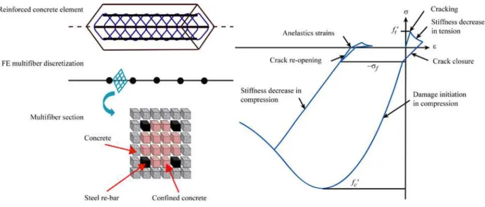
In order to decrease the number of degrees of freedom (DOF) and thus simplify the finite-element mesh, Timoshenko multifiber beam elements are used for spatial discretization (Fig. 2.1) (Guedes & al., 1994; Kotronis & Mazars, 2005; Mazars & al., 2006; Kotronis, 2008). All the computations are performed with the FEDEASLab finite-element code (Filippou & Constandines, 2004).
Figure 2.1. Multifiber beam modeling. Figure 2.2. La Borderie’s cyclic mod el: Uniaxial
stress-strain relation.
2.2 La Borderie’s constitutive model for concrete under cyclic loading
La Borderie’s constitutive model (La Borderie, 1991; La Borderie, 2003) for unconfined concrete under cyclic loading is based on damage mechanics and takes into account the crack opening and closing (Fig 2.2). The model’s general formulation is tridimensional (3D), but only the uniaxial (1D) version is used herein. Total strain ( ) is defined as the sum of an elastic ( ) and an anelastic part ( ) (Eqn 2.1 to 2.4).
(2.1) (2.2)
(2.3)
with i = 1 (traction) or i = 2 (compression) (2.4)
and are, respectively, the tensile and compressive stresses; E is the Young’s modulus; and are material constant parameters controlling the anelastic strains in tension and compression, respectively; is a function that controls crack opening and closing; D1 and D2 (Eqn 2.4) are the damage variables due to traction and compression, respectively, varying from 0 (no damage) to 1 (completely damaged material). Di is piloted by energetic parameters (Yi, and Y0i). Ai and Bi are constants directly identified from uniaxial traction and compression tests. A detailed methodology of this model is presented in (Legeron & al., 2005).
2.3 Eid & Paultre's constitutive model for confined concrete under monotonic loading
Eid & Paultre developed a 1D constitutive model for confined concrete under monotonic loading based on extensive experimental studies (Eid & Paultre, 2008). This global model takes into account internal (due to TSR) and external (due to FRP) confinement (Fig. 2.3). The pre-peak curve in the stress-strain relation is given by Eqn. 2.5, the post-peak relation before FRP failure by Eqn 2.6, and the post-peak relation after FRP failure by Eqn 2.7.
for (2.5)
for (2.6)
for (2.7)
and are the compressive axial stress and strain for the confined concrete; and are the unconfined-concrete cylinder compressive peak strength and strain; and the compressive peak strength and strain of confined concrete (before FRP failure); and the compressive peak strength and strain of steel-confined concrete (after FRP failure); and the confined-concrete cylinder compressive strength and strain at rupture; the slope of the axial concrete stress-strain post-peak curve; a, b, and z are constants that control the initial slope and the curvature of the pre-peak branch; and k1 and k2 are parameters controlling the shape of the post-peak branch. A detailed
description of the model is presented in (Eid & Paultre, 2008).
2.4 Constitutive model for steel
The cyclic behavior of steel bars is simulated using a modified version of the classic Menegotto-Pinto model (Menegotto & Pinto, 1973) with isotropic hardening (Fig 2.4).
Figure 2.3. Eid & Paultre’s monotonic model: Uniaxial
stress-strain relation.
Figure 2.4. Menegotto-Pinto’s cyclic model:
Uniaxial stress-strain relation (isotropic hardening).
3 A NEW MODEL FOR CONFINED CONCRETE UNDER CYCLIC LOADING
In structural RC elements, the main mechanical effect of internal and external confinement is to reduce the development of lateral expansions that cause most of the damage. Under a damage mechanics model, a simplified way to take this into account is to adapt the damage evolution law due to compression. The proposed strategy consists thus in adapting the damage evolution of La Borderie’s model (§2.2) to fit the compressive behavior proposed in Eid & Paultre’s model (§2.3). In the uniaxial version of La Borderie’s model, the axial strain, according to Eqn. 2.1, 2.2 and 2.3, takes the form:
Considering only the uniaxial monotonic compression case ( = ) and after crack closure ( = 0), the relation in Eqn. 3.1 becomes:
(3.2)
D2can therefore be expressed as a function of stress and strain (Eqn. 3.4).
(3.4)
We propose replacing the damage variable D2with a new variable D2c (c for confined) calculated as
follows:
(3.5)
Where is the axial stress in concrete computed from Eid & Paultre’s model (Eqn. 2.8, 2.9, and 2.10). It is assumed that confinement does not affect the unloading process or the tension behavior.
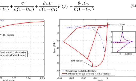
Fig. 3.1 represents the evolution of damage for La Borderie’s model and Eid & Paultre’s model. Clearly, the damage versus strain evolution is slower for the confined concrete than for the unconfined.
The new uniaxial constitutive stress-strain relation for confined concrete is presented in Eqn. 3.6 and Fig. 3.2. The model is validated hereafter using experimental results for FRP confined RC columns and a retrofitted bridge under axial and flexural loading.
(3.6)
Figure 3.1. La Borderie’s and Eid & Paultre’s
models: Evolution of damage versus strain (computed with Eqn. 3.4 and 3.5).
Figure 3.2. Cyclic model for confined concrete: Cyclic
4 SIMULATING RC COLUMNS RETROFFITED WITH FRP
4.1 Experimental set-up
The experimental data used in this section come from tests on FRP reinforced-concrete specimens performed at the University of Sherbrooke (Boucher-Trudeau, 2010). Four FRP confined (P1C to P4C) and four unconfined (P1 to P4) RC cylindrical columns were submitted to axial and cyclic flexural loads (Fig. 4.1 and 4.2). The columns had the same geometrical characteristics, only the FRP thickness, the TSR spacing and the axial load changed for different specimens (Table 1). During the tests, the axial load was kept constant at 10% (P1, P1C, P3 and P3C) or 35% (P2, P2C, P4 and P4C) of the estimated column capacity in uniaxial compression ( ). A horizontal cyclic displacement was applied at the top of each column till failure. A detailed description of the tests is available in (Boucher-Trudeau, 2010).
Figure 4.1. RC column under cyclic loading:
Experimental set-up.
Figure 4.2. RC column under cyclic loading:
Geometrical characteristics.
Table 1. RC Columns’ specifications
Column FRP thickness ( ) TSR spacing ( ) Axial load (KN) (%) P1 0 75 234.3 10 P1C 1.016 75 224.3 10 P2 0 75 759.6 35 P2C 1.016 75 866.9 35 P3 0 150 247.7 10 P3C 1.016 150 249 10 P4 0 150 792.7 35 P4C 1.016 150 805.3 35
Figure 4.3. RC column under cyclic loading:
Multifiber finite-element discretization.
4.2 Numerical modeling
Each column was simulated using 5 multifiber Timoshenko beam elements. Each multifiber beam section contained 24 concrete fibers and 6 fibers for the longitudinal reinforcement steel bars (Fig. 4.3). The column base was assumed to be fixed and its upper part free to rotate and move. Material properties come from experiments presented in (Boucher-Trudeau, 2010).
4.3 Numerical results versus experimental data
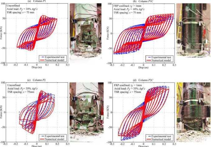
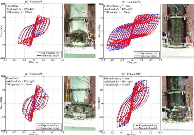
Comparison of the numerical versus the experimental results is presented in Fig. 4.4.a and 4.4.b It is important to note that computations were performed as in “blind” test conditions. Only the ultimate strength value (for the concrete, steel, and FRP), the initial Young’s modulus (for steel and FRP), and the location of the steel bars were considered known in advance.
The significant gain in resistance and ductility due to the FRP confinement was correctly reproduced with the new model. Furthermore, the hysteretic loops show good agreement with the experiment data.
Figure 4.4.a. Retrofitted and regular RC columns under cyclic loading: Force at the base vs. top displacement.
Figure 4.4.b. Retrofitted and regular RC columns under cyclic loading: Force at the base vs. top displacement.
Axial loading = 35% of
5 CASE STUDY: RETROFITTED BRIDGE PIER UNDER AXIAL AND FLEXURAL LOADING
5.1 Experimental set-up
The presented model for confined concrete has been used to simulate the behavior of a bridge-pier mockup under cyclic and seismic loading (Fig. 5.1). The bridge-pier mockup (1/3 scale) was subjected to 7 pseudo-dynamics tests followed by a cyclic test till failure (Roy et al, 2006). The two outer columns were retrofitted with FRP after the first pseudo-dynamic test. An initial axial loading (10% of
) was applied at the top of each column using a displacement control system. The cyclic lateral displacement was imposed above the top of the center column.
Figure 5.1. Retrofitted bridge pier:
experimental setting.
Figure 5.2. Retrofitted bridge pier: Multifiber finite-element
5.2 Numerical modeling
Each column was discretized with 5 Timoshenko multifiber beam elements (Fig. 5.2). Each section contained 24 concrete fibers and 15 fibers representing the longitudinal steel bars. The transverse beam was assumed to be elastic with a reduced section to take into account the initial cracks in the concrete and to correctly fit with the initial stiffness of the structure. The bridge was considered fixed at the base.
The proposed concrete model (§3) was adopted for the two retrofitted columns and La Borderie’s model for the unconfined central column. The steel was modeled with the modified Menegotto-Pinto model. Due to the high number of cycles, and based on the Miner’s theory, the numerical results are improved by taking into account the low-cycle fatigue effects in the reinforced steel bars (Desprez, 2010).
5.3 Numerical versus experimental results
The 7 pseudo-dynamics tests were successively simulated in order to calculate the initial variable distribution of damages for the cyclic test. Only the cyclic-testing simulations are presented hereafter. Fig. 5.3 shows the comparison between the numerical and the experimental results, considering the new confined concrete model. Clearly, the numerical model can reproduce a strength peak similar to the experimental response. Furthermore, the hysteretic loops are in good agreement with the experimental data. Fig. 5.4 shows the comparison without considering the confinement effect.
Figure 5.3 Bridge pier under cyclic loading:
Numerical modeling using the new model for confined concrete and steel fatigue effects.
Figure 5.4. Bridge pier under cyclic loading:
Numerical modeling without taking into account the confiement ant fatigue effects.
6 CONCLUSIONS
This paper presented a new simplified modeling strategy for reproducing the nonlinear cyclic behavior of FRP- retrofitted RC columns. More specifically:
• La Borderie’s unilateral cyclic model for unconfined concrete was modified to take into account the internal (due to TSR) and external (due to FRP) confinement effects. The confinement effects induce changes in the compression damage index. Eid & Paultre’s monotonic model for internal and external confined concrete was used to define the new damage evolution.
• The proposed model was used to simulate experimental tests on FRP-retrofitted RC columns and a bridge pier. Spatial discretization was provided with multifiber beam elements. Results shows that the
strength and ductility increase were correctly described. Moreover, the hysteretic behavior found numerically was close to experimental data.
• During the bridge-pier tests, early steel-bar failure appeared, induced by low-cycle fatigue phenomena. Low-cycle fatigue was introduced into the numerical modelling according to Miner’s theory.
The simplified methods presented in this paper can serve as numerical tools for quick comparative studies on structure vulnerability before and after FRP retrofitting (Desprez, 2010).
In subsequent studies, the proposed model could be extended to deal with various confinement situations. Since Eid & Paultre’s model is suitable for circular FRP-confined columns, the proposed cyclic model could be extended to other column geometries (e.g. square) and wrapping materials (e.g. ductile) using the corresponding monotonic confinement model.
Acknowledgements
The authors are grateful for the financial support of the ANR program ARVISE (Analyse et réduction de la vulnérabilité sismique du bâti existent), Projet ANR-2006-PGCU-007-01). The pseudo-dynamic substructure tests of the bridge pier composed of 3 columns were performed by Nathalie Roy at the University of Sherbrooke. The cyclic flexure and constant axial load tests on eight retrofitted and regular RC columns were performed by Mathieu Boucher-Trudeau at the University of Sherbrooke.
REFERENCES
Boucher-Trudeau M. (2010). Comportement en flexion composée de poteaux circulaires en béton arme confines par des polymères renforcés de fibre de carbone (PRFC), Master dissertation, CRGP, Sherbrooke University, Canada (QC).
Desprez C. (2010). Analyse et réduction de la vulnérabilité sismique des structures existantes: Renforcement par collage de tissus de fibres de carbone (TFC), Doctoral thesis, Institut National Polytechnique de Grenoble, France, 2010, (http://tel.archives-ouvertes.fr/tel-00560438/fr/).
Eid R, and Paultre P. (2008). Analytical model for FRP-confined circular reinforced concrete columns. Journal of Composites for Construction 2008; 12(5):541–552.
Filippou F, and Constandines M. (2004). FEDEASLab getting started guide and simulations examples, Department of Civil and Environmental Engineering. UC Berkeley, USA.
Guedes J., Pégon P. and Pinto A. (1994). A fibre Timoshenko beam element in CASTEM 2000, Special publication nr. i.94.31. Technical report, J.R.C, I-21020, European Comission, Ispra, Italy.
Kotronis P. and Mazars J. (2005) Simplified modelling strategies to simulate the dynamic behavior of R/C walls, Journal of Earthquake Engineering ; 9(2):285–306.
Kotronis P. (2008). Stratégies de modélisation de structures en béton soumises à des chargements sévères, Habilitation à diriger des recherches, Université Joseph Fourier, France. (http://tel.archives-ouvertes.fr/tel-00350461/fr/).
La Borderie C. (1991). Phénomènes unilatéraux dans un matériau endommageable: Modélisation et application à l’analyse des structures en béton, Doctoral thesis, Université Paris VI, Paris, France.
La Borderie C. (2003). Stratégies et modèles de calculs pour les structures en béton, Habilitation à diriger des recherches, Université de Pau et des Pays de l’Adour, France.
Legeron F., Paultre P. and Mazars J. (2005). Damage mechanics modeling of nonlinear seismic behavior of concrete structures. Journal of Structural Engineering, 131(6), 946–955.
Mazars J., Kotronis P., Ragueneau F. and Casaux G. (2006). Using multifiber beams to account for shear and torsion: Applications to concrete structural elements, Computer Methods in Applied Mechanics and engineering 2006; 195(52):7264–7281.
Menegotto M., Pinto P. (1973). Method of analysis of cyclically loaded reinforced concrete plane frames including changes in geometry and non-elastic behaviour of elements under combined normal force and bending, IABSE Symposium on resistance and ultimate deformability of structures acted on by well-defined repeated loads, final report, Lisbon, Portugal.
Roy N., Paultre P. and Proulx J. (2006) Evaluation of a performance based CFRP seismic retrofit of a bridge bent with pseudo-dynamic tests including substructuring, Revue Canadienne de Génie Civil 2010; 37(3):367–379.