Any correspondence concerning this service should be sent
to the repository administrator:
[email protected]
This is an author’s version published in:
http://oatao.univ-toulouse.fr/24919
Open Archive Toulouse Archive Ouverte
OATAO is an open access repository that collects the work of Toulouse
researchers and makes it freely available over the web where possible
To cite this version: Bouzekri, Elodie and Canny, Alexandre and
Martinie De Almeida, Celia and Palanque, Philippe and Barboni, Eric and
Navarre, David and Gris, Christine and Deleris, Yannick Revisiting
system's pages in engine indication and alerting system for flight crew
using the DSCU architecture and the OQCR system generic state
description. (2019) In: INCOSE International Conference on Human
System Integration (INCOSE HSI 2019), 11 September 2019 - 13
September 2019 (Biarritz, France).
Revisiting Systems’ Pages in Engine Indication and
Alerting System for Flight Crew Using the DSCU
System Architecture and the OQCR Systems Generic
State Description
Elodie Bouzekri, Alexandre Canny,
Martinie Celia, Philippe Palanque,
Eric Barboni, David Navarre
ICS-IRIT, Toulouse University
31062 Toulouse, France
[email protected]
Christine Gris, Yannick Deleris
AIRBUS Operations
316 Route de Bayonne
31060 Toulouse, France
[email protected]
crew via the cockpit display system.
This discretization process requires abstracting information away in order to present only meaningful information (in terms of operations) to the flying crew. Indeed, aircraft systems behavior may be very complex (e.g. an engine) and abstracting away information that is not relevant for operations is a challenge. Such concerns have been clearly stated in [2], where MCDU (Multi-function Control and Display Unit) has been identified as issues for pilot when transitioning to glass cockpits. Abstraction can be performed by removing information (e.g. not presenting vibration level of an engine to the crew) or grouping information on equivalence classes of values for a given parameter (e.g. presenting thresholds such as battery voltage is above or below 20%). Such abstraction mechanisms are heavily dependent on the type of the parameters and on the context of use of these parameters and thus no generic rule can be applied. Besides, when all the relevant information is presented, it is still difficult for the flying crew to identify the current state of the system and to answer questions such as “According to the values displayed can I still perform my mission (i.e. follow the flight plan)?”.
Another problem is that the aircraft systems are connected to each other and that a given device (e.g. an engine) can provide multiple services to the aircraft (e.g. bleed, electricity or thrust) that are relevant to the crew. Understanding (and representing) this chain of connected systems is of prime importance when designing HMIs for pilots. Indeed, connecting operations (i.e. mission) and the underlying aircraft systems is the only way to reduce workload as identified in [2]. For instance, bleed can be provided by the engines and/or the APU (Auxiliary Power Unit). Bleed status thus depends on the current functioning of these two aircraft systems. The number of instances also depends on the aircraft types (e.g. 2 or 4 engines).
In this paper, we propose a twin approach to tackle these problems:
· A generic system architecture describing the complexity of aircraft systems and the relationship
ABSTRACT
Engine Indication and Alerting System for Flight Crew provides flying crew with information about aircraft systems. This information covers both nominal and abnormal systems’ states as well as recommended remedial actions to handle abnormal situations. According to the complexity of systems to be managed (e.g. an aircraft engine) information and states must be abstracted away so that flying crew is not overwhelmed. We propose a double mechanism to support such activity: a generic description of states of aircraft systems called OQCR and a hierarchical decomposition of aircraft systems architecture called DSCU. We show how these two contributions provide systematic means to represent aircraft systems and their relationships as well as their nominal and abnormal states. We demonstrate their application on two system pages from large commercial aircraft showing how they can be used to support HMI designs. We also highlight how these contributions can be generalized to other domains.
Keywords
System Architecture, Aircraft Cockpits, Systems State Representation, Human-Machine Interfaces.
INTRODUCTION
Aircraft cockpits are complex systems (in terms of design, development and use) providing flying crew with means for interacting with multiple aircraft systems. Cockpits integrate in one single location the information about these systems as well as the commands to exploit them. The Engine Indication and Alerting System for Flight Crew is the system that integrates parameters of aircraft systems such as engines, hydraulic or fuel [1]. While aircraft systems are mainly analogous in terms of information they produce (e.g. temperature, rotation speed, etc.), this information is discretized when presented to the flying
between those systems. This generic architecture is made up of four types of components: System Devices, System services, Compound services and User services (and is called DSCU);
· A classification of states for each of the elements of the DSCU architecture. This classification is made up of two state descriptors (Operational and Qualitative) and of two attributes for the state descriptors (Restrictions and Context). This classification is called OQCR.
The paper is structured as follows. Next section presents the global organization of modern aircraft cockpits focusing on the Engine Indication and Alerting System for Flight Crew. It presents such systems for both A350 (ECAM) and B777 (EICAS) highlighting commonalities and differences. We then present the generic architecture (DSCU) in section 3 and the state classification (OQCR) in section 4. Section 5 (entitled “Case Study: OQCR and DSCU Applied to AIR COND System”) presents the application of both contributions on the AIR COND systems and demonstrates how the results can be used to design abstract Human Machine Interfaces. Last section highlights lessons learned, concludes the paper and identify future directions for this work.
ORGANIZATION AND PRESENTATION OF SYSTEMS’ INFORMATION IN AIRCRAFT COCKPITS
Aircraft equipped with glass cockpit present information to the flying crew using multiple Display Units (DU). The Main Instrument Panel of both A350 (Figure 1) and B777 contain six Display Units organized in a similar way. The DUs present information either permanently (e.g. altitude, airspeed, etc.), dynamically (e.g. recommended recovery action after a failure) or on demand (e.g. flight plan).
Figure 1. Display Units layout on the Airbus A350 Main Instrument Panel.
The Engine Indication and Alerting System for Flight Crew is responsible for displaying:
· Information related to the aircraft systems (engines, bleed air system, etc.) using system-oriented pages; · Alerts;
· Recommended recovery actions corresponding to these alerts (displayed respectively on the Warning Display of the A350 and the Electronic Check List of the B777);
· Memo and advisory messages associated to the current aircraft status.
This section presents how these three kinds of information are presented on both the B777 and the A350 and details what can be learnt from existing HMIs to propose a generic state-based description of the aircraft systems status.
Synoptic Pages/System Display Pages
The Synoptic Pages (EICAS) or System Display Pages (ECAM) are pages designed to provide, on demand, an overview of the status of an aircraft device or system. The B777 proposes seven Synoptic pages while the A350 proposes 13 SD pages. On both aircraft, we can distinguish i) pages/sections focusing on a specific device (e.g. Auxiliary Power Unit (APU)) and ii) system-specific pages that depicts how a set of devices produces or uses a given system (e.g. the Bleed Air System (BAS)).
Device-specific Pages
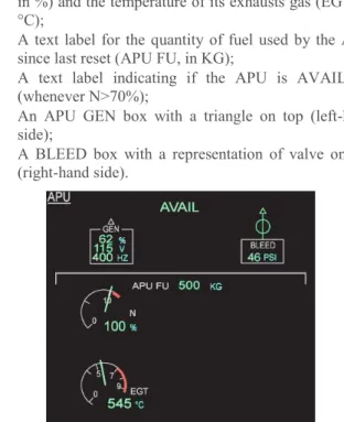
On the A350 and the B777, the Auxiliary Power Unit is a fuel-powered turbine capable of producing bleed air and electricity. On the A350, the monitoring of the APU is possible through the “APU” SD Page (Figure 2). This page presents, during normal operations:
· Gauges presenting the speed of the APU Turbine (N, in %) and the temperature of its exhausts gas (EGT, in °C);
· A text label for the quantity of fuel used by the APU since last reset (APU FU, in KG);
· A text label indicating if the APU is AVAILable (whenever N>70%);
· An APU GEN box with a triangle on top (left-hand side);
· A BLEED box with a representation of valve on top (right-hand side).
Figure 2. The A350 APU SD Page
On the B777, there is no full Synoptic page dedicated to the APU. However, the STATUS page contains an “APU” box (Figure 3) that presents, during normal operation, labels for the turbine rotation (in percent Rotation Per Minute) and turbine EGT as well as the APU oil in terms of pressure, temperature and quantity.
Figure 3. The B777 APU information on the STATUS page
One can observe that Figure 2 presents (in addition to operational parameters related to the APU turbine), information about bleed air (BLEED box, top-left of Figure 2) and electricity produced by APU (GEN box, top-right of
Figure 2). No information regarding what the APU produces is given on the “APU” box of the B777 STATUS page (Figure 3). Such differences makes the impact of turning on/off or losing the APU not directly perceivable on the B777 APU box.
Whenever the APU is running as expected, the “AVAIL” message is displayed at the top of the “APU” SD page. No such message is present on the “APU” box on the STATUS page of the B777, meaning that establishing if the APU is running properly requires a reading of the RPM value. Note however that both the A350 and the B777 display, at various locations of the cockpit, a permanent reminder (“APU AVAIL” or “APU RUNNING”, respectively) whenever the APU is operating.
During abnormal operations, no additional information is provided on B777 APU box on STATUS page. The diagnosis of a low level of oil for instance requires the reading of the associated numerical value. On the other hand, the A350 APU SD page provides various messages and visual indications to highlight failures. Example of such messages and indications are presented in Table 1. Here, while no numerical values related to the APU oil is displayed, the flight crew is still informed of a low level of oil (Line #1 in Table 1). The level of severity of the messages is presented via color-coding. For instance, on line #2, the APU N overspeed in red is associated to a malfunction that will cause an emergency shutdown of the APU after a confirmation time. The amber associated to value on line #3 and #4 indicates non-critical malfunction that have no immediate impact on the APU while the green message “OIL LEVEL LO” of line #1 acts as a reminder.
Table 1. Example of variation of visualization during abnormal operations on the APU SD Page.
# Visualisation Description of fault/failure 1 The APU oil level is low.
2 APU N rotation speed is equal to, or more than, the APU N red limit.
3 The APU generator voltage is abnormal. 4 The APU BLEED valve is abnormally closed.
From the description of these two cockpits we can see that while the devices are similar (APUs) the type of information, the level of detail of that information and the way this information are presented differ. The differences lay in the level of abstraction of this information. Some information is abstracted away until not presented anymore (e.g. Oil in the A350) or on the contrary, more detailed (both a graphical and numeric information about APU speed in A350 and only numeric value on B777). This demonstrates the fact that abstraction is managed differently by designers of those systems and that the actual state of the aircraft device requires specific pilot knowledge e.g. the RPM nominal value (100%) is 48 800. Beyond, abnormal situation are presented through color-coding
adding to the value itself that information about the operational status of the device.
System-specific Pages
After the APU specific information page, we present how a similar abstraction mechanism is applied on a broader system (the air bleed), receiving input from multiple devices including the APU presented above.
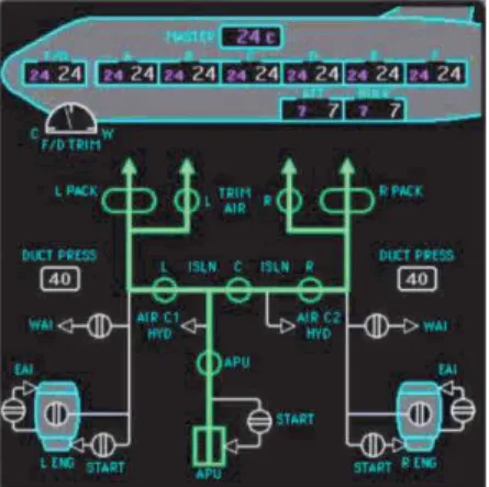
Figure 4 presents the A350 “BLEED” SD page and Figure 5 presents the B777 “AIR” Synoptic page, both during normal operation. We observe that their structure is similar. Indeed, the “AIR” Synoptic (Figure 5) presents the information of the B777 Bleed Air System (BAS). The upper part (depicting an aircraft fuselage) integrates the information related to air conditioning. The air-conditioning information is presented on a specific SD page called “AIR COND” in the A350 (that we do not present due to space constraint). Thus, the layout of the B777 “AIR” Synoptic page makes explicit the relationship between the BAS and the air-conditioning while the A350 “BLEED” SD page does not.
Figure 4. The A350 BLEED SD page.
While information such as bleed air pressure are presented on both aircraft (30 PSI on the A350 (Figure 4) and DUCT PRESS 40 on the B777 (Figure 5)), we observe that other information such as the bleed air temperature in only presented on A350 (150°C on Figure 4). This shows that some information has been abstracted away on the B777 during normal operation.
Figure 5. The B777 AIR synoptic page present both BLEED and AIR COND information
Regarding abnormal operations, both aircraft propose variation of visualizations (based on shapes and color coding) on the “AIR”/”BLEED pages (see Table 2).
Table 2. Example of variation of visualization during abnormal operations on the BLEED page/AIR synoptic. A350 BLEED B777 AIR Description of fault/failure
The bleed air pressure is abnormal The valve is abnormally closed.
Beyond this information presentation aspect about the bleed system, it is important to note that bleed air is produced by three devices including the APU and both engines. This structure of service production is graphically represented in the pages (bottom of Figure 4 and Figure 5) showing additionally the fact the there is an additional service called bleed routing. This bleed routing system (composed of pipes/ducts, valves) is also graphically represent using symbols (see last line of Table 2) and the fact that it connects bleed to the devices is made explicit through this representation.
Alerting System/Warning System
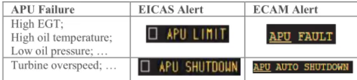
The Alerting System (EICAS) and the Warning System (ECAM) are responsible for the presentation of (i) Abnormal and emergency procedures and (ii) Limitations and Memos. In both systems, the procedures are associated to alerts (EICAS and ECAM Alert column in Table 3) triggered by conditions such as those presented in the first column of Table 3. In these APU-related examples, the APU continues to either operate abnormally (APU LIMIT/FAULT) or automatically stops (APU (AUTO) SHUTDOWN). An important highlight here is that multiple failure lead to the same alert abstracting away information (especially the causes of the alert).
Table 3. Examples of EICAS and ECAM Alert for APU faults.
APU Failure EICAS Alert ECAM Alert
High EGT; High oil temperature; Low oil pressure; … Turbine overspeed; …
Abnormal and emergency procedures are the recommended recovery actions provided by the Engine Indication and Alerting System for Flight Crew following the occurrence of a fault/failure.
After completing a procedure, some systems may become non-available either because of their own state (e.g. the APU after a fire) or because of the execution of a procedure (e.g. closing some of the BAS valves after a bleed leak). Both EICAS and ECAM provide a mechanism to remind the flying crew about those inoperative systems as presented in Figure 6 (inoperative systems after a bleed leak on the A350). First line tells that engine 1 will not provide bleed anymore as well as the APU (second line).
Figure 6. Inoperative Systems on the A350 after a bleed leak
In addition to impacting aircraft systems and services (e.g. bleed), the execution of some procedures may also limit the aircraft operational capabilities. Figure 7 presents an example of limitation for the A350 stating that pilots must do not use the manual mode of the cabin pressurization because it is totally lost.
Figure 7. Example of LIMITATIONS on the ECAM WD Analysis of Existing Presentation Organization and System Presentation in Cockpit
In this section, we presented some of the displays of existing Engine Indication and Alerting Systems for Flight Crew used in different aircraft. The information structuring and information abstraction we highlighted drove us to the observations presented below.
Obs. 1: During normal operations, parameters values may be replaced by abstract information indicating whether a device is on, off, starting, etc.
With the example of the APU, we noted that whenever the APU is running (i.e. when its speed is >70%), the B777 and A350 respectively display “APU RUNNING” or “APU AVAIL”. Beyond, during normal operation it is not necessary to look at the operational parameters of the “APU” page/box to determine if the APU is running as expected, as this information is directly presented next to the parameters.
Obs. 2: During abnormal operations, display of parameters value may be replaced by information indicating if the device/system is either in a degraded mode or stopped working.
Table 3 shows that for a set of APU malfunctions related to abnormal values of operational parameters (e.g. oil and EGT), the same EICAS/ECAM alert is presented to the flight crew. When one of these alerts occurs, the APU may either stop functioning (APU (AUTO) SHUTDOWN) or continue to operate in an abnormal configuration (APU LIMIT/FAULT). Therefore, values of operational parameters may be replaced by an information indicating how severely the device is impacted by the variation of parameters as the actual value does not impact the state of the device.
Obs. 3: Aircraft systems are impacted by the variables of related systems that may prevent using them even though their operational parameters are “healthy”.
In Figure 6, we note that following a leak in the BAS, some systems are reported inoperative even though they are not faulty. For instance, APU bleed is presenting as faulty even though the APU device is fully functional. This is presented as bleed system is not able to receive bleed from the APU (due to the bleed leak). We claim that flight crew may take advantage of a detailed description of the relationship between service providers (e.g. APU bleed) and service consumers (Bleed system). This connection is currently partly represented (see Figure 4 and Figure 5), but not in a global and systematic way.
With these observations in mind, we propose:
1) a generic architecture for aircraft systems to describe devices, systems and services connectivity in a systematic manner (Obs. 3) presented in next section, 2) a generic state description taking into Obs. 1, 2 and 3
in order to propose generic states for devices, systems and services that would be the basis for abstract information presented in the HMI of aircraft cockpits.
A GENERIC ARCHITECTURE FOR AIRCRAFT SYSTEMS
Previous section shows that system pages may differ significantly one from another showing sometimes the information of a dedicated device (e.g. APU page of the A350) or blending information from multiple devices (e.g. engines and APU bleed and bleed routing together with their connections as on Figure 5). While some elements are physical devices (e.g. APU) other ones are more complex and multifaceted elements (e.g. bleed). From the physical devices to the services used by the pilots and passengers (e.g. air conditioning) there is a variety of different types of interconnected systems. Defining a generic architecture, we propose to make explicit both these categories and their relationships in order to decompose the complexity of aircraft systems.
Detailed Presentation of the Components of the Architecture
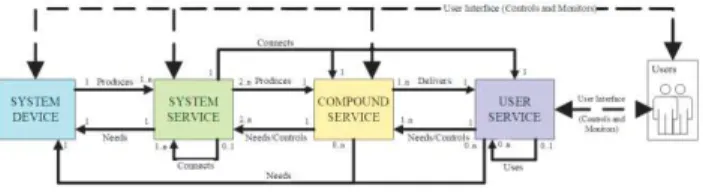
Figure 8 presents the proposed DSCU generic architecture which decomposes what is usually called aircraft systems into four different types of components: System Device, System Service, Compound Service and User Service. Their relationships are shown on Figure 8, which is presented in details from left to right in the following sections.
Figure 8. Generic Architecture of aircraft systems System Device
A System Device (the component on the left-hand side of Figure 8) is the primary device responsible of the production of services. The System Device may need other components for performing its functions and thus providing
its services to other components of the architecture (represented by the arrows from the three types of service to System Device). System Devices have a state that may be presented to the users (pilots) on a user interfaces of command and monitor (dotted line at the top of Figure 8). A System Device can be a routing device (e.g. only composed of valves and pipes) enabling the delivery of a routing service.
For example, the Figure 2 presents the APU and the BLEED routing (BLEED valve), which are System Devices according to DSCU architecture. The System Device APU produces two services: BLEED and GEN and needs fuel for its operation.
System Service
A System Service is a service enabled by the System Device. The production of a System Service relies on only one System Device. A System Service has a state that may be presented to the users. A System Service can be a routing service. A routing service may contributed to and produce other System Services.
For example, the APU GEN and the APU BLEED (APU SD page in Figure 2), are System Service according to DSCU architecture. APU BLEED is transported by a BLEED routing System Service. Similarly APU GEN System Service needs a routing service (electrical network) to be transported, but this service is not explicitly represented on the APU SD page but the ELEC SD page represents it.
Compound Service
A Compound Service is a combination of several System Services. A Compound Service is responsible of the synthesis and integration of all the System Services enabling the delivery of a resource of interest from the system point of view (e.g. a service that is not directly used by the human user but that can be used by other systems). A Compound Service has a state based on the System Services states that produce it. This state may be presented to the users.
For example, Figure 4 presents BLEED, which is a Compound Service according to DSCU architecture. The composition of APU BLEED, ENG 1 BLEED and ENG 2 BLEED System Services produce (altogether) the BLEED Compound Service.
User Service
A User Service is a service of interest for the user. At least one Compound Service delivers a User Service. A routing System Service transports a User Service. The User Service has a state that can be computed from the state of each Compound Service that delivers it. This state may be presented to the user.
For example, Figure 5 (top) presents AIR COND, which is a User Service according to DSCU architecture. The crew and passengers directly use AIR COND for their comfort. We use AIR COND User Service is in the illustrative example section of the paper.
Each components of aircraft systems described using DSCU architecture has a state that may be presented to the pilots, this is why they are all connected to the user (via user interfaces) on the architecture. If we consider that pilots activities in the cockpit are structured around four main activities: 1) Fly 2) Communicate 3) Navigate and 4) Manage Systems, the supervision and management of the state of systems and services are part of Manage Systems activity of the pilots. Manage Systems activity requires, for each system, to understand how resources availability and consumption affect systems performances. The flying crew is primarily interested in the user services but may need to drill down to service, routing services and devices when faults occur and interfere with the normal delivery of the user service. Going back to the presentation of the information in the cockpit (previous section of the paper) this is where abstraction takes place. Devices and routing services are numerous and usually analog with continuous variables describing their state. This information has to be abstracted away to provide only meaningful and relevant information to the crew.
Next section proposes a systematic grouping of states for devices and services described in a DSCU architecture.
THE OQCR STATE DESCRIPTION
Manage Systems activity requires (among other) consulting overhead panel and processing ECAM information and in particular the SD pages. In section 2, we highlighted that discrete information presented on SD pages describes the evolution of state of the device that we call here the
operation state (e.g. ramping up, running). For example,
the N speed indication or EGT (Exhaust Gas Temperature) indication for the APU presented in Figure 2 have to be perceived and interpreted by the pilot to understand that the APU is running, demonstrating the usefulness for an abstract information.
Another key indication on SD pages is the state of the
quality of operation. Most of the time, this state is
represented using thresholds (exceeded or not) and thus going from continuous values to discrete one. For example, N OVERSPEED threshold of the APU presented in Figure 2 corresponds to an abstraction of the current speed of the APU turbine. For abnormal conditions, a modifier (a color such as amber) is used to represent that additional information (as seen in Table 1). Similarly, amber indication on a system or service indicate its degraded state. During the training, the pilot learned performance issues of some systems in given particular contexts. For example, according to FCOM of A350 [5], the System Service APU BLEED is in its context of use up to an altitude of 25 000 feet and out of context of use above. In case of some alarms, the pilot can read restrictions on the use of some systems. For example, according to the FCOM of the A350 [5] such restrictions will be presented with the indication “DO NOT USE” next to the name of the device or service. Such restriction is presented in Figure 7.
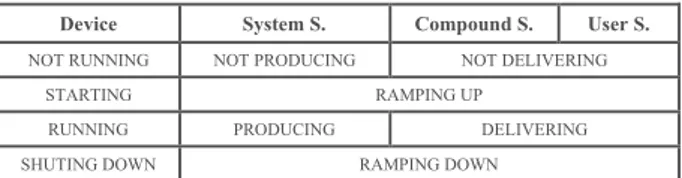
In the following sections, we detail two generic categories for describing the states of systems and services. The first one is called Operation state (with four possible values) and the second called Qualitative state (with three possible values). These two categories cover the set of descriptions presented above. Beyond these two categories we propose the addition of Context attribute and of a Restriction attribute to represent more precisely the relationship between the states and the operations. These four elements, called OQCR, makes it possible to precisely represent systems and service states in an abstract way, i.e. without presenting the value of their internal parameters. While the categories apply to every component of DSCU, we propose different values (names of the states) according to type of component (see Table 4).
Operational and Qualitative (OQ) States
The Operation State of a system or a service describes in an abstract way its current behavior and is meant to provide immediate usable information to the crew. Table 4 presents the set of values of the Operation State for each components of the DSCU architecture.
It should be noted that for some systems or services like ELEC Compound Service, “ramping up” and “ramping down” are transient states, meaning that the state change occurs very quickly and that it might not be relevant to present those transient state changes to the crew. Other components might need more time e.g. APU and thus presenting the information “starting” is relevant.
Table 4. Operation State for the DSCU components
Device System S. Compound S. User S.
NOT RUNNING NOT PRODUCING NOT DELIVERING
STARTING RAMPING UP
RUNNING PRODUCING DELIVERING
SHUTING DOWN RAMPING DOWN
The Qualitative State of an element describes how well this element performs (if enabled) or will perform (if disabled). Table 5 presents the values of the Qualitative State for each components of the DSCU architecture. When the device (or service) is “degraded”, it means that a failure occurred on the device (or service) and an associated alarm is usually displayed. When the device is “out of order” (or a service “out of service”), it means that the device (or service) is no longer capable to run (or to deliver) for the rest of the mission. In current cockpits, a service “APU BLEED” is presented within the list of INOP SYS (Figure 6).
Table 5. Values of the qualitative state
Attribute Definition
FUNCTIONAL The device can run properly. The service is produced or delivered as required. DEGRADED
The device is not capable of running properly and suffers performance penalty. The service cannot be
produced or delivered as required. OUT OF
ORDER/SERVICE
The device is not capable to run. The service cannot be produced or delivered for the entire
Context and Restriction (CR) Attributes
The Context attribute indicates if the device or service evolves in a context that matches its specifications. The context is defined in aircraft systems by variables such as resources availability, flight envelope, flight phase, etc. Table 6 presents the values of the Context Attributes (applicable to all DSCU components).
Table 6 Context attribute of state
Context Attribute Definition
WITHIN CONTEXT The device or service is in its nominal context of use.
OUT OF CONTEXT The device or service is not in its nominal context of use.
The usage Restriction attribute represents the impact of the current context of the aircraft on the availability of services or devices. Table 7 presents the possible values of the Restriction attribute (applicable to all DSCU components) for each components of the DSCU architecture. The “not allowed” value indicates that the component must not be in use in any case, even though it is “functional” and “within context”. For example, a “not allowed” system is represented with the “do not use” mention on the limitations display of A350 ECAM (see Figure 7).
Table 7 Restriction attribute of state
Restriction Attribute Definition
ALLOWED The device or service can be use.
NOT ALLOWED The device or service must not be in use.
OQCR Summary
Each type of components of DSCU architecture has a state made up of two states values and two attributes values as summarized in Table 8. With the OCQR approach, we can describe any state of a device or a service with one value out of twelve (for the state part), which as then to be completed by contextual information about the current operation of the aircraft (two additional values). In current cockpits, this information is sometimes already presented (e.g. APU avail in Figure 2) but might also be combined with continuous values e.g. temperature) or an abstraction of a value (percentage of the speed of the APU turbine). We believe this generic identification of states provides designers and flying crew with a mean for systematically considering internal systems or service states.
Table 8. Structure of an OQCR state/attributes description
O
Q
C
R
Operational state
Qualitative state Context attribute Restriction attribute 1 value out of 4 1 value out of 3 1 value out of 2 1 value out of 2
It is important to note that, during operation, it might not be possible for the sensors to capture information about a device or system. In that case, the value of each of the four attributes of OQCR might be unknown (in addition to all the other values presented).
CASE STUDY: OQCR AND DSCU APPLIED TO AIR CONDITIONING SYSTEM
This section presents the application of both DSCU and OQCR to a large aircraft system. This case study aims at demonstrating the applicability of the proposed contribution to real case examples. It also demonstrates its scalability beyond the small examples used as illustration. Finally, it proposes some prototypes of HMIs to present such information to the flying crew.
The Airbus A350-900 is equipped with an air conditioning system (called AIR COND) supplied by the Bleed Air System (BAS) that is electrically powered. In flight, the BAS supplies two air conditioning PACKs with air from the engines and/or the APU. The packs are the unit responsible of cooling the hot bleed air from the turbines. In early design stage of the A350, the APU performances were assumed to be insufficient to provide sufficient airflow for dual packs operations above 22 500ft. In such case, the ECAM would have presented the AIR APU BLEED LIMITED TO SINGLE PACK OPER alarm and its associated procedure. Not following this procedure would have resulted in the failure of a PACK and the presentation of associated alert. While the final version of the aircraft is not prone to such behavior thanks to the final APU characteristic, the work presented in this case study is based on this early design stage scenario that remains easy enough to discuss within the space constraint for this paper. Below we applied the DSCU architecture on the Air Cond service. Then, we illustrate the OCQR states of the different systems and services involved.
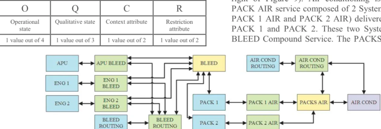
DSCU Architecture for the AIR COND System
Figure 9 presents the DSCU architecture applied to AIR COND system and its resources. AIR COND is defined as a User Service because passengers and crew are final users of this service which affects their comfort. AIR COND is provided using AIR COND Routing System Service enabled by the AIR COND Routing System Device (top right of Figure 9). Air conditioning is produced using PACK AIR service composed of 2 System services (called PACK 1 AIR and PACK 2 AIR) delivered by the devices PACK 1 and PACK 2. These two System Devices need BLEED Compound Service. The PACKS AIR Compound
Figure 10. Prototype presenting information integrating both DSCU and OQCR in the scenario
Service transforms the PACK 1 AIR and PACK 2 AIR System Services into a usable AIR COND. From the left-hand side of Figure 9 it is visible that ENGines and APU System Devices produce the BLEED Compound Service feeding PACK 1 and PACK 2 system devices.
Figure 9, presents on a single diagram a complex set of devices and services together with their connections that contribute to the production of the user service AIR COND. We believe that the DSCU decomposition and structuring provide a systematic and efficient way to represent complex aircraft systems.
HMI Prototypes for AIR COND
This section presents some examples of HMI (Human-Machine Interfaces) for presenting information about aircraft system to the flying crew. We only present those prototypes related to the AIR COND system, exploiting both the DSCU architecture of AIR COND presented in Figure 9 and the OQCR state decomposition. To make things more concrete, we propose the HMI in a context of a scenario, in which ENG 1 BLEED and ENG 2 BLEED are NOT PRODUCING
(1) Initially, the aircraft flies at FL200 and all aircraft devices and services are working properly. Especially, the AIR COND is DELIVERING-FUNCTIONNAL-WITHIN CONTEXT-ALLOWED. Following an ATC instruction to climb, pilot flying changes the autopilot ALT settings to climb to FL250. As the aircraft crosses the FL225, the AIR COND context attribute changes. The “AIR APU BLEED LIMITED TO SINGLE PACK OPER” alarm is displayed. Following OQCR structure, AIR COND user service is now DELIVERING-FUNCTIONNAL-OUT OF
CONTEXT-ALLOWED. Figure 11 presents a mockup of a visualization such an AIR COND state.
Figure 11. Mockup for AIR COND (scenario 1)
(2) In that scenario, pilots fail to react fast enough, the BLEED AIR supply becomes insufficient to feed the air conditioning packs triggering the display of “AIR PACK 1 FAULT”. Applying OQCR, AIR COND service is now DELIVERING-DEGRADED-OUT OF CONTEXT-ALLOWED. A mockup of presentation of this state is shown in Figure 12.
Figure 12. Mockup for AIR COND (scenario 2)
Figure 10 proposes an example of prototype that presents the states of all systems and services at the end of the scenario. The structure of the prototype follows DSCU architecture and information about each device and each service contributing to AIR COND is displayed. More precisely, because of “AIR PACK 1 FAULT” alarm the PACK 1 is now INOPerative (top-right corner of Figure 10). In consequence, the PACK 1 Qualitative state is OUT OF ORDER. Its state Context attribute is OUT OF CONTEXT because of the lack of APU BLEED resource. Indeed, previously in the scenario, the aircraft crosses FL225 and the APU BLEED get out of its specification of
usage. As a consequence, the “AIR APU BLEED LIMITED TO SINGLE PACK OPER” alarm is triggered. Following OQCR, APU BLEED Qualitative state is now DEGRADED (see third line of system service box on the right-hand side of Figure 10).
Although the prototype must be revised with a User Centered Design process conducted with pilots, it is interesting to note that the prototype of Figure 10 is very different from the current user interfaces in large civil aircraft. There are multiple ways to move forward from it: 1) use the prototype as a complementary display offering
abstract information about services and systems. Flying crew would keep using Engine Indication and Alerting System for Flight Crew pages to get more precise information about systems and services 2) use the prototype as complementary interactive
prototype so that users can interact directly with it to
get more information but also to trigger commands on systems and services
3) use the prototype as full interactive Engine Indication and Alerting System for Flight Crew so that users can interact with it to get more information but also to trigger commands on systems and services. It would be the main device for the activity manage systems. Engine Indication and Alerting System for Flight Crew could become a complementary device to it.
CONCLUSION AND PERSPECTIVES
The work presented here fits well within the Cyber-Physical Systems [11] (CPS) domain with a deep grounding in large civil aircraft systems.
This paper has presented a double contribution. First, a cyber-physical systems architecture dedicated to aircraft systems. Second, a generic decomposition of the states of the components of the DSCU architecture taking into account both normal and abnormal situations. We have presented a set mockups and a prototype for presenting such state information to the flying crew. The prototype provides an abstract, generic and systematic representation supporting the task “Manage Systems” of large civil aircraft. It could thus be complementary to the current EICAS and ECAM systems that were introduced in the beginning of the paper. We demonstrated the use of the contribution to the AIR COND system. After these steps, usability testing and training costs analysis need to be performed.
We believe the proposed approach is applicable to other cyber-physical systems such as medical devices or large command and control rooms such as nuclear power plants. The DSCU architecture would remain unchanged but the values of OQCR would require tuning according to the
terminology used in that domain. The paper addresses known challenges in the CPS domain such as state descriptions [9], architecture [10] and command and control interface aspects [12].
REFERENCES
1. Wells A.T. and Rodrigues C. C.(2004). Commercial aviation safety (4th ed.). McGraw-Hill Professional. p. 245.
2. Sherry L, Polson P., Feary M., Palmer E. When Does the MCDU Interface Work Well? Lessons learned for the design of New Flightdeck User Interfaces. Proc. of HCI Aero 2002 conference, p 180-185.
3. Stanton N., Baber C., Walker G. H., Houghton R. J., McMaster R., Stewart R., Harris D., Jenkins D., Young M. S., Salmon P. M. Development of a generic activities model of command and control. Cogn Tech Work (2008) 10:209–220
4. Smalley J (2003) Cognitive factors in the analysis, design and assessment of command and control systems. Handbook of cognitive task design. Lawrence Erlbaum Associates, pp 223–253
5. Airbus A350 Flight Crew Operating Manual, 5T1 A350 FLEET FCOM. Technical Report. Airbus. 6. Fahssi R., Martinie C., Palanque P. Embedding explicit
representation of cyber-physical elements in task models. IEEE System Man and Cybernetic conference 2016: 1969-1974
7. European Aviation Safety Agency. 2017. CS-25 – Certification Specifications and Acceptable Means of Compliance for Large Aeroplanes. (2017).
8. Bhave A., Krogh B. H., Garlan D., and Schmerl B. 2011. View Consistency in Architectures for Cyber-Physical Systems. IEEE/ACM Second int. Conf. on Cyber-Physical Systems. 151–160
9. Broy M. & Schmidt A. 2014. Challenges in
Engineering Cyber-Physical Systems. Computer 47, 2, 70–72
10. Jensen J. C., D. H. Chang, and E. A. Lee. 2011. A model-based design methodology for cyber-physical systems. In 2011 7th Int. Wireless Communications and Mobile Computing Conf. 1666–1671.
11. Edward A. Lee. 2016. Fundamental Limits of Cyber-Physical Systems Modeling. ACM Trans. Cyber-Phys. Syst. 1, 1, Article 3, 26 pages.
12. Paelke V. and Rocker C.. 2015. User Interfaces for Cyber-Physical Systems: Challenges and Possible Approaches. Springer International Publishing, Cham, 75–85