HAL Id: hal-02137104
https://hal.archives-ouvertes.fr/hal-02137104
Submitted on 22 May 2019HAL is a multi-disciplinary open access
archive for the deposit and dissemination of sci-entific research documents, whether they are pub-lished or not. The documents may come from teaching and research institutions in France or abroad, or from public or private research centers.
L’archive ouverte pluridisciplinaire HAL, est destinée au dépôt et à la diffusion de documents scientifiques de niveau recherche, publiés ou non, émanant des établissements d’enseignement et de recherche français ou étrangers, des laboratoires publics ou privés.
MHOMS : high speed ACM modem for satellite
applications
Sergio Benedetto, Claude Berrou, Catherine Douillard, Roberto Garello,
Domenico Giancristofaro, Alberto Ginesi, Luca Giugno, Marco Luise, G.
Montorsi
To cite this version:
Sergio Benedetto, Claude Berrou, Catherine Douillard, Roberto Garello, Domenico Giancristofaro, et al.. MHOMS : high speed ACM modem for satellite applications. IEEE Wireless Communications, In-stitute of Electrical and Electronics Engineers, 2005, 12 (2), pp.66 - 77. �10.1109/MWC.2005.1421930�. �hal-02137104�
MHOMS: High Speed ACM Modem for Satellite Applications1
S. Benedetto(3), C. Berrou(5), C. Douillard(5), R. Garello(3), D. Giancristofaro(1), A. Ginesi(2), L. Giugno(4), M. Luise(4), G. Montorsi(3),
(1) Alenia Spazio (2) European Space Agency
(3) Politecnico di Torino (4) Università di Pisa
(5) ENST Bretagne
Table of Contents
1 Introduction... 1
2 Modulation schemes and signal detection/synchronisation techniques... 2
2.1 Modulation formats selection and digital pre-distortion ... 2
2.2 Synchronisation techniques... 3
3 Code design trade-off... 7
3.1 Serial Concatenated Convolutional Codes ... 7
3.2 Low Density Parity Check Codes ... 8
3.3 Parallel Concatenated Convolutional Codes ... 8
3.4 Coding schemes trade-off... 9
4 Performance of MHOMS modulation and coding scheme ... 13
5 Conclusions and outlook ... 15
1 Introduction
Within the satellite communications innovation trend, some key issues, such as: • usage of increasingly high frequency bands (e.g., from X, Ku, up to Ka and Q;). • the higher frequency reuse achievable with multi-beam satellite antenna technology;
• the increasing satellite RF power becoming available thanks to the platform technology improvement;
• the exploitation of capacity boosting Adaptive Coding and Modulation (ACM) techniques in addition to power control to reduce the static link margin and matching the physical layer to the location and time dependent SNIR [1], [2]
are shifting the focus from classical satellite modulation schemes, such as QPSK, to higher order M-ary modulation schemes. The latter can provide a higher spectral efficiency and thus the data rate required for either multi-media applications or for applications such as point-to-point high data rate backbone connectivity, and future Earth Observation missions requiring down-link data rates exceeding 1 Gb/s.
Usage of the higher frequency bands, while providing improved bandwidth and clear sky link budget for a given user station antenna dish size, implies the need to cope with an increased depth of fading events as well as a higher level of local oscillators’ phase noise. The above mentioned problems can be mitigated by the exploitation of Fade Mitigation Techniques (FMT) such as gateway site diversity, ACM for physical layer, power control etc…) and robust demodulator synchronisation techniques possibly inserting pilot symbols. Notwithstanding the above technological improvements, satellite RF power still represents the key cost driver of satellites and calls for efficient
1The present contribution describes the achievements obtained within the ESA funded MHOMS program (Modems for
on-board high-power amplification. To achieve the required power efficiency, highly efficient coding shall be associated with a wide range of (high-order) modulation schemes, optimised for the non-linear satellite channel operation. On the demodulator side, the challenge is to cope with the high-speed link requirements and to extract synchronisation and channel estimation accurate enough to avoid impairing the data recovery process even in presence of challenging phase noise disturbances2, at the low E
s/N0 imposed by the state of the art coding solutions. This paper reports some very satisfactory outcomes of the Modem for Higher Order Modulation Schemes (MHOMS) project funded under the Technology Research Program of the European Space Agency (ESA). The MHOMS program is aimed at the research, design development and demonstration of an innovative high-rate, very high-speed, on-the-fly re-configurable satellite digital modem prototype, with maximum bit rate of 1Gbps supporting a wide range of spectral efficiencies (from 0.5 to 5.4 bps/Hz). The modem performance requirements for all operational modes (spectral efficiencies) are set to a very small distance from the Shannon capacity bound (about 1 dB at a 10-5 FER). Furthermore, specified losses for modem operation over a typical Ka-band satellite non linear channel shall be low calling for innovative modulation/demodulation schemes design. One of the goals of the activity is to demonstrate feasibility of core HW section of the physical layer, which requires highly innovative design approach, since it is expected to achieve unprecedented throughput/efficiency maximisation in the satellite communication link. This is particularly true for the demodulator/decoder sub-system that will require truly innovative high-speed architectures. The current contribution focuses on the results of the study phase 1 which aimed at the specification of a flexible yet power and spectral efficient (de)coding, (de)modulation, synchronisation techniques able to satisfy the challenging requirements set forth. Phase 2 will lead to detailed design, implementation and test of the demonstrator. Comprehensive details of the modem are presented in [3].
The envisaged MHOMS modem application scenarios will encompass as a minimum: • High-speed Distributed Internet Access;
• Trunk Connectivity (Backbone/Backhaul); • Earth Observation high-speed down-link;
• Point-to-multipoint applications (e.g. high-speed multicasting/broadcasting).
Among the above application scenarios, particular commercial interest is expected for the broadcasting/multicasting and Internet access applications. Since this application is the main target of the DVB-S2 (Digital Video Broadcasting, Standard No.2) standardisation group, the team has actively contributed to DVB-S2 definition [4]. With respect to the DVB-S2 (limited to the forward link) the MHOMS work is also encompassing more advanced functionalities such satellite beam hopping requiring a different frame structure and enhanced reverse link compared to the current DVB-RCS (Return Link over Satellite). Furthermore, the high throughput required has led to selection of less complex (but more efficient) code solutions endowed with performances similar to those offered by the DVB-S2 LDPC (Low Density Parity Check Codes) codes.
2 Modulation schemes and signal detection/synchronisation
techniques
Together with state-of–the art coding, soon addressed, new approaches to the issue of modulation and signal detection / synchronisation have been taken into account. Two main aspects were considered in this respect; namely, non-linear distortions introduced by the High-power Amplifier (HPA) on-board the satellite on one hand and low-SNIR robust synchronisation on the other. We remind that the MHOMS demonstrator discussed in this paper is devoted to the forward link (from a gateway to many user stations), and the high rate TDM (Time Division Multiplexing) signal subject of the transmission is assumed to be amplified individually by a TWTA (Travelling Wave Tube Amplifier). This is the basis for the addressed pre-distortion techniques applicability.
2.1 Modulation formats selection and digital pre-distortion
2 The phase noise used for the design and throughout the performance simulations is the commercial user equipment mask defined in the DVB-S2 standard [2].
Concerning non-linear distortions, two basic approaches were investigated. The first one is proper design of the constellations to be used. Traditional square- or cross-QAM (Quadrature Amplitude Modulation) constellations in fact have a high peak-to average power ratio, that cause non-negligible AM/AM and AM/PM distortions (Amplitude to Amplitude and Amplitude to Phase conversion) when the signal is amplified by the HPA. This remark led to the “rediscovery” and optimisation of different multi-level Amplitude- and Phase-Shift Keying (APSK) constellations based on concentric “rings” of equi-spaced points, such as the 4-12 APSK (a inner 4PSK constellation surrounded by an outer 12PSK) shown in Figure 1 and so on for 32 APSK and 64 APSK [5]. In 4-12 APSK for instance, the modulation symbols bear two different amplitudes only, thus minimising envelope fluctuations in the transmitted signal. This in turn results in lower distortion onto the HPA-amplified received signal. By proper Minimum Euclidean distance-based APSK constellation parameters optimisation, APSK showed superior performance over non-linear satellite channels and almost identical performance compared to QAM over linear AWGN channel. The 16 APSK and 32 APSK constellations proposed by the authors have been retained by the DVB-S2 standard [4]. The second approach to minimise the effect of non-linearity is adaptive constellation (data) pre-distortion in the transmitter. Pre-distortion means intentionally modifying the location of the data symbols on the complex plane with respect to their nominal position. Such a technique only calls for a modification of the transmitted constellation points, without the need to resort to analogue devices. This is particularly straightforward and effective for circular constellations such as APSK. Details are discussed in [6].
Different pre-distortion schemes were investigated, based either on “instantaneous” evaluation of the distortion at the receiver (adaptive static pre-distortion), or on the consideration of a certain amount of “memory” in the combined phenomenon of non-linear distortion plus matched filtering at the receiver (so called adaptive dynamic pre-distortion) [7].
The set of tested modulation schemes for MHOMS includes “conventional” QPSK or 8-PSK modulations, two-ring 16-ary, three rings 32-ary and four ring 64-ary APSK constellations (see fig. 1). Thanks to the coded APSK constellation and pre-distortion techniques, in single-carrier mode the HPA can be operated remarkably close to saturation. This is particularly true for 16 APSK which can optimally operate at Input Back-Off (IBO) very close to 0 dB. It turns out that with pre-distortion, the HPA can be operated remarkably close to saturation, e.g. down to 1.5 dB average Output Back-Off in the case of 16-point constellations with highly-efficient channel coding (Turbo or LDPC). The interested reader is referred to [3].
Figure 1
:
Multi-ring APSK constellations: a) Euclidean distances, b) 16-points 4-12 APSK; c), 32-points 4-12-16 APSK; d) 64-points 4-12-20-28 APSK.2.2 Synchronisation techniques
As for signal synchronisation, the receiver has to be able to work with powerful channel coding (turbo with large block length) with an operating Es/N0 ratio considerably lowered with respect to more conventional coding schemes
with shorter code blocks and/or smaller coding gains. Also, consumer grade terminal equipment are considered as assumed in DVB-S2 [4], which implies particularly strong phase noise. The best that a synchronisation unit can do in this respect is given by the performance of data-aided algorithms, that can only be applied on pilot symbols known to the receiver in advance. On the other hand, insertion of pilot symbols decreases the efficiency of the link, reducing the net Eb/N0 ratio on information bits.
Novel techniques especially for blind carrier phase recovery (which is needed to perform coherent detection and channel decoding) were also investigated. In particular, by exploiting the Expectation Maximisation (EM) algorithm [8], soft-decision-directed iterative phase estimation combined with iterative channel decoding (the so-called
turbosync approach) was shown to be applicable both to continuous- and to burst-mode operation of the modem,
even in the presence of large amounts of oscillator phase noise. With long codewords, the phase noise has relevant variations over the channel code block. This means that correcting the carrier phase using a constant term over the entire frame is useless. One of the most efficient approaches is subdividing the block in L sub-blocks, each one encompassing a pilot symbol field and a “payload” section. The pilot section is needed for “pre-compensating”, with a data aided estimate, the overall phase error in the subsequent payload section, so that the fine phase tracking algorithm can operate within its phase acquisition range (about [-30,30] degrees). The resulting framing structure is shown in figure 2, where it is worth noting that a further pilot symbol field is placed at the end of the frame.
Obviously, the performance depends on the pilot symbol density µ , defined as P P D N N N µ= + (1)
where ND symbols is the data field length and NP is the pilot section length. For each constellation, we found an optimal value of η represents the best trade off between two opposite constraints. First, it is necessary to minimise the loss in power efficiency due to the insertion of pilot symbols (need to have a short pilot section); second, we want to achieve an estimate of the carrier phase as accurate as possible (need to lengthen the pilot section).
Sub-block Sub-block ...
D
N
Frame Marker (FM) + Frame Acq. (FA) Sub-block
256 .symb 2 P N Sub-block 2 P N
Figure 2 – Pilot distribution scheme. The overhead for each frame field is finally assumed as follows:
Frame Marker (FM) plus frame acquisition (FA): 256 symbols.
Pilot overhead: NP=18 pilot symbols every ND=405 data symbols for QPSK (overhead 4.25%) and NP=12 pilot
symbols every ND=405 data symbols otherwise (overhead 2.87%). The size of each code word (in channel symbols) is fixed at 8,100 symbols and the number of sub-blocks is equal to L=20.
Finally, we report the outline of the baseline synchronisation procedure, which is particularly suitable for ACM mode.
a) Coarse Carrier Frequency Acquisition
In consumer-grade terminal equipment, the initial frequency error can be as large as 5 MHz at cold start-up, i.e. up to 50% of the minimum signalling rate (10 Mbaud). This prevents clock recovery from being the first synchronisation task to carry out, and dictates that at least a coarse frequency offset compensation be performed first. Initial frequency estimation is accomplished by means of a digital oversampled AFC loop [9]. The relevant frequency discriminator is a two-samples-per-symbol delay-and-multiply (D&M) FED (Frequency Error Detector). With QPSK modulation, at E Ns 0 = −1.85dB operating point, the D&M loop allows to correct the symbol-rate normalised RMS frequency to about 10−3 remaining error. This is achieved in approximately 5 Msymbols, i.e., 500 ms or less with the lowest signalling rate equal to 10 Mbaud. This complies with DVB-S2 recommendations for cold start-up, acquisition and re-acquisition after a deep fade.
b) Symbol Timing Synchronisation
Once the normalized frequency offset is brought down to around 10−3, the next task to be carried out is symbol timing synchronisation. The selected scheme for timing acquisition and tracking is a two-samples-per-symbol first-order timing with Gardner’s timing error detector (TED) [10] and cubic interpolation that provides a symbol-synchronous output sequence.
c) Coarse Digital Automatic Gain Control
In order to recover the amplitude of the received symbols to the average one of the ideal constellation, the symbol-synchronous sequence at the interpolator output is processed by a slow non-coherent pseudo-ML NDA Digital Automatic Gain Control (DAGC) [11].
d) Start-of-Frame (SoF) detection
The symbol sequence at the DAGC output undergoes further processing for SoF detection, which can be easily carried out with a 128-symbol FM in a quasi-coherent mode in view of the very low residual frequency offset.
e) Fine Carrier Frequency Adjustment
As next step, fine frequency estimation is achieved by means of the Luise & Reggiannini [L&R] algorithm over the FA field [12]. This exhibits a low complexity but also a narrow acquisition range, which is to be compatible with the residual frequency offset after coarse frequency compensation.
f) Joint Fine Amplitude Tracking and Carrier Phase Acquisition and Tracking
Phase Noise tracking is accomplished by performing conventional open-loop data-aided phase estimation on the pilot fields of the frame, and then performing a (modified) linear interpolation between two consecutive pilot fields to track the phase variation on the data fields, similarly to the approach presented in [13]. Then, we resort to a modified weighted decision directed digital 2nd order phase locked loop (MWDD-DPLL) or to a code-aware synchronisation process, the so-called “Hard Turbo Synch” (HTS) [8], to perform fine phase tracking and, at the same time, fine amplitude adjustment, according to the well-known EM (Expectation Maximisation) algorithm framework.
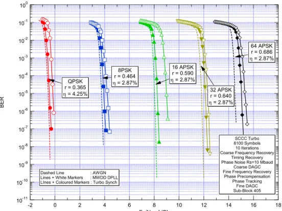
The overall final performance of the modem with synchronisation loss and with the lowest code rate is represented in Figure 3.
It is worth noting that, depending on the modulation order, with MWDD-DPLL and HTS the above mentioned losses are equal to 0.25÷1.1 and 0.1÷0.6 dB in terms of signal-to-noise ratio, respectively.
10-11 10-10 10-9 10-8 10-7 10-6 10-5 10-4 10-3 10-2 10-1 100 BE R 18 16 14 12 10 8 6 4 2 0 -2 Es/N0 , [dB] SCCC Turbo 8100 Symbols 10 Iterations Coarse Frequency Recovery
Timing Recovery Phase Noise Rs=10 Mbaud
Coarse DAGC Fine Frequency Recovery
Phase Precompensation Phase Tracking Fine DAGC Sub-Block 405 QPSK r = 0.365 η = 4.25% 8PSK r = 0.464 η = 2.87% 16 APSK r = 0.590 η = 2.87% 32 APSK r = 0.640 η = 2.87% 64 APSK r = 0.686 η = 2.87%
Dashed Line : AWGN Lines + White Markers : MWDD DPLL LInes + Coloured Markers : Turbo Synch
Figure 3 - Performance with overall synchronisation loss: HTS vs MWDD DPLL with sub-block length ND=405
3 Code design trade-off
Parallel Concatenated Convolutional Codes (PCCC), Serially Concatenated Convolutional Codes (SCCC), and Low Density Parity Check codes (LDPC) have been investigated. All the pre-selected schemes allow to achieve the desired flexibility and maintain excellent performance, very close to the sphere packing lower error bound.
3.1 Serial Concatenated Convolutional Codes
For SCCC, the innovative pragmatic scheme depicted in Figure 4 has been designed.
It consists of an outer and inner encoders stemming from the same 4-state, rate ½, recursive, systematic encoder shown in the same figure. For all the SCCC rates but ¼ the outer encoder is punctured to a rate 2/3 through the optimal puncturing reported in the figure.
In order to obtain the desired SCCC rate, we perform puncturing at the output of the inner encoder, according to the scheme shown in Figure 4. The upper register at the output of the inner encoder contains the N+2 inner systematic bits, which coincide with the interleaved outer code word plus the 2 bits terminating the inner trellis. The lower register, instead, contains the N+2 parity-check bits generated by the inner encoder. Two different puncturing algorithms are used to puncture bits in the upper and lower registers. Puncturing in the upper register is performed on the N inner systematic bits (excluding the 2 inner code terminating bits that are always transmitted) according to a puncturing pattern periodic with period 200 trellis steps, which correspond in our case to 300 outer coded bits. The systematic bits of the inner encoder correspond to the code word generated by the outer encoder, so that the puncturing pattern on these bits has been designed to maximise the free distance of the outer encoder, and take into account that puncturing occurs after interleaving. Aiming also at high code rates, it is computationally complex to exhaustively optimise the puncturing patterns for the outer encoder. Thus, we used a slightly sub-optimal, yet manageable, searching algorithm that works incrementally, in a rate-compatible fashion, so that the punctured positions for a given outer rate are also punctured for all higher rates.
Optimisation of the upper register puncturing pattern involves both the number of bits to be punctured, and their position. A design procedure for the outer code puncturing yielding outer code rates in the whole range
200 / 300≤Ro ≤200 / 201has been developed for this purpose.
Rate ½ 4-state RC Interleaver Interl. Rate ½ 4-state Punc. sys Punc. parity Fix Punct. 11 10 u S S P S bits P bits Mapping Modulation m bits u c1 c2
Figure 4: Block diagram of the SCCC scheme
Puncturing bits in the lower register, which contains the parity-check bits generated by the inner encoder, is obtained by applying a rate matching algorithm. The simulation results show that the newly proposed scheme offers good performance in a large range of code rates, including very high ones.
3.2 Low Density Parity Check Codes
For LDPC, a new class of “modular” parity check matrixes has been investigated. These codes have a linear encoder complexity and are particularly suited for parallel implementation of the decoder algorithm. The codes have been optimised for high SNR performance, since FER as low as 10-7 are required by most considered applications. For limiting encoding complexity, we impose the following structure on the parity check matrix H of the designed LDPC codes C(n=k+m,k):
p d
H= H H
where Hd is an m by k matrix, and Hp is a dual diagonal m by m matrix just as chosen for the DVB-S2 standard code. This allows encoding complexity reduction.
The random part of the matrix, Hd have been designed by properly distributing smaller square sub-matrices l by l , a structure which helps parallel decoder architectures. Each of them can be:
• An all-zero matrix
• A matrix obtained by cyclically shifting the l by l diagonal matrix
The position of the non-zero matrices and their respective cyclic shift are chosen using the Progressive Edge Growth (PEG) algorithm [14]. This algorithm guarantees that every time a non-zero matrix is added, its position and cyclic shift are chosen so that the girth (length of minimal cycles) of the graphs is as large as possible.
The performance of the designed LDPC are very good, showing limited penalty with respect to theoretical lower bounds. The decoding complexity of the designed coding schemes, which is essential for proper comparisons, has been deeply analysed and discussed [15] and [3]. This aspect is indeed fundamental for our applications, due to very high data-rates and required flexibility.
3.3 Parallel Concatenated Convolutional Codes
A flexible turbo has been devised for the adaptive coding and modulation scheme of MHOMS. This code, called TurboΦ, is derived from the extension of the DVB-RCS turbo code [16] to 16 states [3]. Replacing the DVB-RCS 8-state turbo code by a 16-8-state code leads to a gain in performance of up to 1.5 dB at a FER of 10-6. Figure 5 shows the structure of the TurboΦ encoder for coding rates greater than 0.5.
S1 S2 S3 S4
Y Redundancy part Systematic part
A B
Constituent convolutional encoder
C onstituent encoder Permutation (s ize N)
Π
Puncturing Y1 or 2 A B 1 2 N = k / 2 couples of dataFigure 5. Block diagram of the TURBOΦ PCCC encoder (R ≥ 1/2).
The encoding of a data block involves encoding information data with the convolutional encoder in the natural order (switch in position "1"), and then encoding it again in the permuted order (switch in position "2). Information or systematic data are transmitted only once.
The natural coding rate R of the turbo encoder described in figure 5 is equal to 0.5. In order to obtain greater values for R, a regular puncturing is performed at the output of each constituent encoder. For coding rates lower than 1/2, the encoder in figure 5 can be modified following two possible solutions:
− Either input B is not used, thus transforming the “double-binary” convolutional code into a classical binary code,
− Either a second redundancy symbol is generated each time.
The former technique was applied to obtain the performance curves displayed in figures 6 and 7 for R = 1/3.
Both constituent encoders call for the tail-biting termination technique [17] that allows the trellis of the convolutional code to be viewed as a circle, thus transforming it into a block code. This termination technique presents several advantages in comparison with the classical trellis termination technique using tail bits to drive the encoder to the all-zero state. In particular, no extra bits have to be added and transmitted; thus there is no rate loss and the spectral efficiency of the transmission is not reduced. Moreover, when classical trellis termination is applied for turbocodes, a few codewords with input Hamming weight 1 may appear at the end of the block (in both coding dimensions) and can be the cause of a marked decrease in the minimum Hamming distance of the composite code.
The permutation function Π is based on the so-called Almost Regular Permutation (ARP) principle described in [18]. It is built from a regular permutation calling for circular shifting [19]. Regular permutation is appropriate for error patterns with input weight 2 or 3, and more generally for non-decomposable error patterns. In ARP permutations, some disorder has been carefully instilled, so as to avoid low-weight composite error patterns and to obtain large minimum Hamming distances. Furthermore, this algorithmic permutation law is simple to implement with a few dozen logic gates, and the parameters can be changed on-the-fly for adaptive encoding and decoding. Moreover, as explained in [18], massive parallelism, allowing several processors to run at the same time without increasing the memory size, can be exploited. As an example, implementing parallelism allows data to be decoded at a rate equal to 200 Mbit/s by a CMOS 0.18µ ASIC decoder performing 8 decoding iterations. Such a decoder implementation requires approximately 180,000 to 200,000 logic gates. The same decoder can also be implemented on a Xilinx Virtex2-4000 FPGA, and can decode at a rate equal to 70 Mbit/s. Increasing parallelism can lead to higher data rate, at the price of a raised complexity.
3.4 Coding schemes trade-off
In previous sections we have described candidate coding schemes drawn from the class of PCCC, SCCC and LDPC codes. In this section, we will propose a few criteria used as “goodness” measures to rank the proposed schemes and draw some preliminary conclusions. We have used the following criteria to compare and rank the described codes:
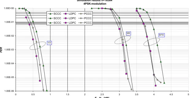
1. Performance. We will use as performance measure the Eb/N0 required to achieve a FER=10-6; QPSK modulation has been adopted and both short and long codewords have been considered. The information block size is either 428 or 16,384 and code rates 1/3, 5/6 and 9/10 have been used for both. As a matter of fact, it has been demonstrated during the study that if a code performs well with QPSK, it will also do it with higher order modulation schemes. In Figure 6 and Figure 7 we report the FER for the three candidate coding schemes with QPSK modulation, rates 1/3, 5/6, and 9/10 with short and long block sizes. The results have obtained by simulating at least 10 million frames. Whenever the curve stops at a FER above 10-6 no errors have been found for the corresponding Eb/N0 . This is not true only for the case of PCCC with rate 9/10
and long block size that exhibits an error floor.
2. Complexity. As complexity measure we will use the numbers of elementary operations (arithmetic complexity) per decoded bit and memory requirements (memory complexity). 3. Flexibility. We will comment on the flexibility of the proposed schemes as their ability to cope
with the stringent requirement of modifying the rate, block size and modulation on a per frame basis.
4. Number of iterations required. This number impacts on the complexity parameter, essentially as a multiplicative parameter of the estimated arithmetic complexity. We prefer, however, to keep it as a separate item in this preliminary stage, since its effect on the overall complexity depends on the chosen decoder architecture.
5. Maturity. We will comment on the maturity of the proposed schemes in terms of existing implementations and general industrial acquaintance with them.
Simulation results, k=428 4PSK-modulation 1.00E-06 1.00E-05 1.00E-04 1.00E-03 1.00E-02 1.00E-01 1.00E+00 0 1 2 3 4 5 6 7 8 9 10 Eb/N0 [dB] FE R SCCC LDPC PCCC SCCC LDPC PCCC SCCC LDPC PCCC 1/3 5/6 9/10
Figure 6: FER performance of PCCC, SCCC and LDPC for the short block size and all three code rates. Simulation results n=16384 4PSK-modulation 1.00E-06 1.00E-05 1.00E-04 1.00E-03 1.00E-02 1.00E-01 1.00E+00 0 0.5 1 1.5 2 2.5 3 3.5 4 4.5 5 Eb/N0 [dB] FER SCCC LDPC PCCC SCCC LDPC PCCC SCCC LDPC PCCC 1/3 5/6 9/10
Figure 7: FER performance of PCCC, SCCC and LDPC for the long block size and all three code rates.
In Table 1, we summarise the comparison criteria for the three classes of codes. The table reports for the short and long block codes the required Eb/N0 for the target FER, the Eb/N0 loss with respect to the best code in dB, the
minimum distance and the number of nearest neighbours when available. In terms of complexity, we report for the short and long block codes the RAM (Random Access Memory) and ROM (Read Only Memory) memory
occupations, the number of sums and MAX/MAX* operators3 per decoded bit (in case of MAX, also the LUT complexity has to be accounted for), the number of iterations, and, finally, the evaluation of the other comparison criteria.
3.4.1 The performance comparison
For the short block size, the PCCC scheme offers the best performance. It yields a gain from 0.3 dB (rate 1/3) to 1.05 dB (rate 9/10) over SCCC, and from 0.5 dB (rate 1/3) to 1 dB (rate 9/10) over the LDPC.
For the long block size, the LDPC scheme offers the best performance but is close to those of the SCCC and PCCC (gains from 0.15 to 0.25 dB), except for PCCC rate 9/10, that has greater losses for SNR greater than 4.3 dB. None of the schemes show the presence of error floors, except for rate 9/10 PCCC; for rate 5/6 this PCCC phenomenon is milder, showing only a slight slope change. For the rate 1/3, PCCC loss is less than 0.1 with respect to LDPC and 0.25 for SCCC with respect to LDPC. For R=5/6, SCCC and PCCC loss with respect to LDPC behaves differently but is approximately 0.15 dB for both. For rate 9/10 it is difficult to state the PCCC loss in absence of the results at FER=10-6, while the worst SCCC loss is only 0.25 dB.
The extrapolation of the last two points of the curves in Figure 7 (4.3 dB) for SCCC and LDPC to reach 10-6 is "conservative”; this means that the next point has been simulated for at least 10 million frames without finding an error. For PCCC, the above mentioned point at 4.3dB – for the rate 9/10 case – can be conservatively extrapolated to a FER of about 3.10-6.
3 The MAX* operator on two arguments consists in taking the MAX plus an additive correction term implemented as a look-up table [20].
3.4.2 The complexity comparison
In terms of complexity, the SCCC scheme is the simplest in terms of RAM occupation for all block sizes and rates. On the other hand, the PCCC scheme only requires a little amount of ROM to store the permutation parameters. The LDPC is by far the most complex, this is due to the fact that the number of edges is much larger than the interleaver size of SCCC and PCCC. As to the arithmetic complexity, the SCCC scheme is by far the simplest. It is roughly 2-3 times less complex than the PCCC. The LDPC schemes are from 2 to more than 6 times more complex (depending on the specific case considered), this stems from the larger number of edges and of required iterations for the LDPC schemes, which is not compensated by the lower complexity of the check nodes operation with respect to the SISO processor. Notice also that for high data rates requiring a highly parallel architecture, the differences in terms of area due to the arithmetic operations becomes even more evident.
Code Criterion 1/3 5/6 9/10 1/3 5/6 9/10 1/3 5/6 9/10 Perfo rman ce Short LDPC PCCC - TurboΦ SCCC
Eb/N0 @ Target FER 2 5,4 6,7 2,3 6 7,75 2,5 5,9 8
Loss to best 0 0 0 0,3 0,6 1,05 0,5 0,5 >1,0 dmin, Nmin 36-107 5-32.4 4-337 30-1 5-1 4-3 X X X Perfo rman ce Short Long
Eb/N0 @ Target FER 0,8 3,4 >5,0 0,95 3,4 4,35 0,75 3,25 4,1
Loss to best 0,05 0,15 >1,0 0,2 0,15 0,25 0 0 0 dmin, Nmin 66-1366 11-1365 7-590 66-2 7-1 7-1 X X X Perfo rman ce Comp lexi ty Long Short RAM Memory 12 840 8 988 8 798 10 914 7 059 6 869 34 413 12 641 10 435 ROM Memory 64 64 64 6 420 6 420 6 420 47 988 15 829 12 661 SUM 1860 1730 1730 730 730 730 950 350 250 MAX 1280 1280 1280 - - - -MAX* - - - 370 370 370 1600 900 700 Number of iterations 8 8 8 10 10 10 50 50 50 Comp lexi ty Short Long RAM Memory 163 840 286 720 303 104 139 260 225 276 236 742 552 313 614 137 630 713 ROM Memory 64 64 64 106 490 307 193 331 763 1 142 383 1 292 527 1 332 783 SUM 1860 1730 1730 730 730 730 1250 550 550 MAX 1280 1280 1280 - - - -MAX* - - - 370 370 370 2500 1600 1500 Number of iterations 8 8 8 10 10 10 50 50 50 Comp lexi ty
High Code must be designed for all cases Other issu es Sensitive to interleaver optimization Long Flexibility Maturity
High Code must be designed for all cases Other issu es Sensitive to interleaver optimization
High Medium Low
Table 1: Summary of complexity and performance comparison for the three classes of PCCC, SCCC, and LDPC.
3.4.3 The flexibility comparison
Flexibility refers here to the possibility (and the related complexity/performance consequences) of the co-decoder to adapt to different code rates, modulation schemes, and block sizes on a per frame basis. All schemes can adapt
easily to variations in the modulation schemes, as they are pragmatic schemes, i.e., all make use of a binary encoder whose output bits are mapped to all modulation schemes. These schemes are also known as bit-interleaved coded modulations. The SCCC scheme adapts very easily to different code rates. The same is true for the PCCC scheme. Adaptation to different code rates requires for the LDPC codes to work in general with different codes, which have to be stored. Also, the decoding engine, although general in terms of elementary and repetitive operations, must be able to work with possibly different number of edges entering into and exiting from variable and parity nodes.
3.4.4 The maturity comparison
PCCC have been already implemented in numerous cases, and accepted as standards in several system applications. The only novelty concerns the parallel architectures. SCCC have seen less cases of implementations, but their technology should not pose any further problems. LDPC are relatively newer in terms of applications, although their acceptance in the new DVB-S2 standard should accelerate the full comprehension and solution of implementation problems.
4 Performance of MHOMS modulation and coding scheme
As a results of the previous analysis on performance and complexity, the authors decided to implement, for the forward link, the coding solution based on the SCCC scheme. The choice with respect to PCCC is due to the better behavior in terms of error floor for all rates and lower complexity. With respect to the LDPC, which exhibits slightly better performance for all rates and block sizes, the choice has been dictated by the much lower complexity. Indeed, the SCCC scheme seemed to be the only one viable for implementation using FPGA (Field Programmable Gate Array) devices to reach data rates as high as 1 Gbit/s.
In Table 2 we report the set of encoding-modulation configurations supported by the MHOMS. The rationale for the construction of this table is as follows:
• The working Es/N0 of each configuration must be in steps of roughly 1dB • The maximum rate of the encoder was set to Rc=9/10.
• The maximum spectral efficiency was set to 5.4, obtained with rate 9/10 and 64-APSK • The spectral efficiency, obtained with the unconstrained capacity formula for complex signals
2 0 log 1 Es N η= +
together with the maximum rate constraint determine the used modulations :
10 9
m= η
• The number of modulation symbols in a codeword is fixed to 8,100 and imposed by the framing structure. This leads to a variable number of encoded bits N in the SCCC encoder.
• The previous constraints then fix the nominal values of the SCCC encoder (the information block size K, the interleaver length I, and the codeword size N)
• Constraints imposed on the interleaver lengths that depend on the architecture and parallelism slightly change the interleaver size I to a close value (I’ in the table). As a consequence, also the information block size K, the spectral efficiency and the Es/N0 (coming from the capacity expression) slightly change. The
resulting Es/N0 step is reported in the last column.
• This approach defines the main 19 ACM formats in Table 2, reported with regular font.
• The two highest spectral efficiencies for each modulation scheme have also been included with the modulation scheme with higher cardinality. This overlap is necessary because the coded-modulator performance can be different depending on the channel impairments so that the best ACM solution cannot be determined a-priori. The 8 resulting additional ACM formats are reported with italic font in the table.
Es/N0 eta K I N m Code
Rate K' Ibest eta' Es/N0' delta
1 -1.85 0.7254 5,876 8,817 16,200 2 0.36 5,918 8,880 0.7306 -1.81 2 -0.85 0.8659 7,016 10,527 16,200 2 0.43 6,958 10,440 0.8590 -0.89 0.91 3 0.15 1.0254 8,306 12,462 16,200 2 0.51 8,318 12,480 1.0269 0.16 1.06 4 1.15 1.2039 9,752 14,631 16,200 2 0.60 9,758 14,640 1.2047 1.16 1.00 5 2.15 1.4012 11,350 17,028 16,200 2 0.70 11,278 16,920 1.3923 2.11 0.95 6 3.15 1.6164 13,094 19,644 16,200 2 0.81 13,118 19,680 1.6195 3.17 1.06 7 2.15 1.4012 11,350 17,028 24,300 3 0.47 11,278 16,920 1.3923 2.11 -1.06 8 3.15 1.6164 13,094 19,644 24,300 3 0.54 13,118 19,680 1.6195 3.17 1.06 9 4.15 1.8484 14,974 22,464 24,300 3 0.62 15,038 22,560 1.8565 4.19 1.02 10 5.15 2.0958 16,976 25,467 24,300 3 0.70 16,958 25,440 2.0936 5.14 0.96 11 6.15 2.3568 19,092 28,641 24,300 3 0.79 19,118 28,680 2.3602 6.16 1.02 12 7.15 2.6299 21,304 31,959 24,300 3 0.88 21,278 31,920 2.6269 7.14 0.98 13 6.15 2.3568 19,092 28,641 32,400 4 0.59 19,118 28,680 2.3602 6.16 -0.98 14 7.15 2.6299 21,304 31,959 32,400 4 0.66 21,278 31,920 2.6269 7.14 0.98 15 8.15 2.9133 23,598 35,400 32,400 4 0.73 23,518 35,280 2.9035 8.12 0.98 16 9.15 3.2056 25,966 38,952 32,400 4 0.80 25,918 38,880 3.1998 9.13 1.01 17 10.15 3.5053 28,394 42,594 32,400 4 0.88 28,318 42,480 3.4960 10.12 0.99 18 9.15 3.2056 25,966 38,952 40,500 5 0.64 25,918 38,880 3.1998 9.13 -0.99 19 10.15 3.5053 28,394 42,594 40,500 5 0.70 28,318 42,480 3.4960 10.12 0.99 20 11.15 3.8111 30,870 46,308 40,500 5 0.76 30,878 46,320 3.8121 11.15 1.03 21 12.15 4.1220 33,388 50,085 40,500 5 0.82 33,358 50,040 4.1183 12.14 0.98 22 13.15 4.4370 35,940 53,913 40,500 5 0.89 35,918 53,880 4.4343 13.14 1.00 23 12.15 4.1220 33,388 50,085 48,600 6 0.69 33,358 50,040 4.1183 12.14 -1.00 24 13.15 4.4370 35,940 53,913 48,600 6 0.74 35,918 53,880 4.4343 13.14 1.00 25 14.15 4.7555 38,520 57,783 48,600 6 0.79 38,558 57,840 4.7602 14.17 1.02 26 15.15 5.0766 41,122 61,686 48,600 6 0.85 41,198 61,800 5.0862 15.18 1.01 27 16.15 5.4000 43,740 65,613 48,600 6 0.90 43,678 65,520 5.3923 16.13 0.95 64APSK 8PSK 16APSK 32APSK
Nominal values Interleaver constrained
Q
PSK
Table 2: Available configurations for the MHOMS encoder
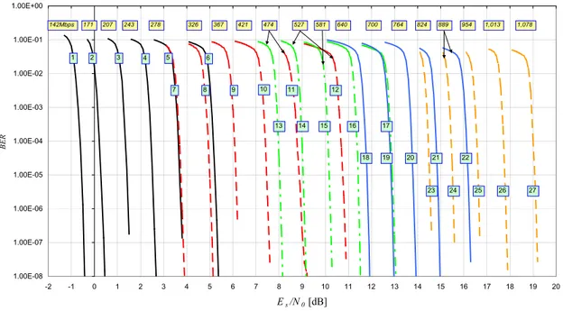
The performance of this 27 ACM formats on the Gaussian channel are reported in fig.7. The data rate labelling the curves refer to the transmission of 2 Mega symbols per second.
1.00E-08 1.00E-07 1.00E-06 1.00E-05 1.00E-04 1.00E-03 1.00E-02 1.00E-01 1.00E+00 -2 -1 0 1 2 3 4 5 6 7 8 9 10 11 12 13 14 15 16 17 18 19 20 Es/N0 [dB] BER 1 2 3 4 5 7 8 11 18 23 142Mbps 243 278 326 367 421 474 527 581 700 824 954 6 9 10 12 13 14 15 16 17 19 20 21 22 24 25 26 27 171 207 640 764 889 1,013 1,078
Figure 7: Simulated BER performance of the 27 ACM formats of the MHOMS.
5 Conclusions and outlook
The paper presented preliminary results from the Phase 1 of the ESA funded MHOMS project aiming at the study design and development of a ultra high-speed, high-performance and fully reconfigurable digital modem. The MHOMS modem will be able to cover future needs of telecommunications and Earth Observation missions and will feature state of-the-art coding, modulation, demodulation, synchronisation and decoding algorithms. The MHOMS technological development will also lay the foundation (building blocks) of a new class of modems able to exploit adaptive coding and modulation for a variety of different applications. During the remaining part of phase 1 activity, the trade-off among the described candidate coding, modulation, pre and demodulation/synchronisation techniques will be finalised and complemented by architectural design considerations. Also possible physical layer improvements for the return link of interactive satellite networks covered by the current DVB-RCS standard will be proposed.
During phase 2 of the activity the MHOMS prototype will be designed, assembled and tested in laboratory set-up inclusive of a satellite channel simulator, aiming at demonstration of the most challenging modem operating modes.
REFERENCES
[1] R. De Gaudenzi, R. Rinaldo, “Adaptive Coding and Modulation for Next Generation Broadband Multimedia
Systems”, in the Proc. of the 20th AIAA Satellite Communication Systems Conference, Montreal, May 2002, AIAA-paper 2002-1863.
[2] R. De Gaudenzi, R. Rinaldo, A. Perez Carro-Rios, “Adaptive Coding and Modulation for the Reverse Link of
Next Generation Ka-band Multimedia Systems”, in the Proc. of the Ka-band 8th Utilization Conference, Baveno, Italy, Sept. 25-27, 2002.
[3] C. Berrou, R. De Gaudenzi, C. Douillard, G. Gallinaro, R. Garello, D. Giancristofaro, A. Ginesi, M. Luise, G. Montorsi, R. Novello, A. Vernucci: “High Speed Modem Concepts and Demonstrator for Adaptive Coding and
Space Communications (SPSC), 23-25 September 2003, Catania (soon available either at www.alespazio.it or www.esa.int).
[4] Digital Video Broadcasting (DVB), “Second generation framing structure, channel coding and modulation
systems for Broadcasting, Interactive Services, News Gathering”, DVB-S2 draft document DVBS2-74, June 2003.
Available on the DVB organisation web site (http://www.dvb.org) [DVB-S2 ftp directory]
[5] R. De Gaudenzi, A. Guillen i Fabregas, A. M. Vicente, and B. Ponticelli, “High Power and Spectral Efficiency
Coded Digital Modulation Schemes for Non-linear Satellite Channels”, in Proc. 7th International ESA Workshop on
Digital Signal Processing Techniques for Space Applications, Sesimbra, Portugal, October 2001.
[6] L. Giugno, V. Lottici, M. Luise, “Adaptive Compensation of Non-linear Satellite Transponder for Uncoded and
Coded High-Level Data Modulations”, to appear on IEEE Transactions on Wireless Communications, September
2004.
[7] G. Karam and H. Sari, “A Data Predistortion Technique with Memory for QAM Radio Systems”, IEEE Transactions on Communications, Vol. 39, No. 2, pp 336-344, February 1991.
[8] V. Lottici, M.Luise, “Embedding Carrier Phase Recovery into Iterative Decoding of Turbo-Coded Linear
Modulations”, IEEE Trans. on Communications, Vol. 52, Issue 4, pp. 661-669, April 2004.
[9] F. Natali: “AFC Tracking Algorithms”, IEEE Transactions on Communications, Volume: 32 , Issue: 8 , Aug 1984 pp. 935 – 947.
[10] F. M. Gardner, “A BPSK/QPSK Timing-Error Detector for Sampled Receivers”, IEEE Trans. on Comm., Vol. 34, n. 5, pp. 423-429, May 1986
[11] R. De Gaudenzi, and M. Luise, "Analysis and Design of an All-Digital Demodulator for Trellis Coded 16-QAM
Transmission over a Non-linear Satellite Channel", IEEE Trans. Commun., vol. COM-43, nos. 2/3/4, Feb./Mar./Apr.
1995, pp. 659-668.
[12] M. Luise and R. Reggiannini, “Carrier Frequency Recovery in an All-Digital Modem for Burst-Mode
Transmissions”, IEEE Trans. Commun., vol. COM-43, nos. 2/3/4, Feb./Mar./Apr. 1995, pp. 1169-1178.
[13] E.Casini, R. De Gaudenzi and A. Ginesi, “DVB-S2 Modem Algorithms Design and Performance Over typical
Satellite Channel”, International Journal of Satellite Communications and Networking, Volume 22, Issue 3,
May/June 2004, pp. 281-318.
[14] Xiao-Yu Hu; Eleftheriou, E.; Arnold, D.-M.; “Progressive edge-growth Tanner graphs,” Global Telecommunications Conference, 2001. GLOBECOM '01. IEEE , Volume: 2 , 2001, pp. 995 -1001.
[15] Politecnico di Torino, ESA MHOMS project WP 1320 activity report (Modems for High-Order Modulation Schemes Contract No. 16593/02/NL/EC, soon available either at www.alespazio.it or www.esa.int ).
[16] DVB, "Interaction channel for satellite distribution systems", ETSI EN 301 790, V1.2.2, pp. 21-24, Dec. 2000. [17] C. Weiss, C. Bettstetter, S. Riedel and D. J. Costello, “Turbo decoding with tail-biting trellises”, in Proc. URSI Int. Symposium on Signals, Systems, and Electronics, pp. 343-348, Pisa, Italy, October 1998.
[18] C. Berrou, Y. Saouter, C. Douillard, S. Kerouédan and M. Jézéquel, “Designing good permutations for turbo
codes: towards a single model” in Proc. IEEE Int. Conf. Communications (ICC), pp. 341-345, Paris, France, June
2004.
[19] S. Dolinar and D. Divsalar, “Weight distribution of turbo codes using random and nonrandom permutations”, TDA Progress Report 42-122, JPL, NASA, Aug. 1995.
[20] S. Benedetto, D.Divsalar, G.Montorsi and F.Pollara, ``Soft-input soft-output modules for the construction and
distributed iterative decoding of code networks'', European Transactions on Telecommunications, invited