This is an author-deposited version published in: https://sam.ensam.eu Handle ID: .http://hdl.handle.net/10985/11383
To cite this version :
Mathilde CROZATIER, Svetlana TEREKHINA, Frédéric DAU, Laurent GUILLAUMAT -Mechanical characterization of composite materials from curved structures - 2016
Any correspondence concerning this service should be sent to the repository Administrator : [email protected]
M. Crozatier, S. Terekhina, F. Dau and L. Guillaumat
MECHANICAL CHARACTERIZATION OF COMPOSITE MATERIALS
FROM CURVED STRUCTURES
M. Crozatier1, S. Terekhina1, F. Dau2 and L. Guillaumat1
1
Arts et Métiers ParisTech, LAMPA, 2 Boulevard du Ronceray, 49100 Angers, France Email: [email protected]
2
Arts et Métiers ParisTech, I2M, Esplanade des Arts et Métiers, 33405 Talence, France
Keywords: curved structures, mechanical characterization, inverse approach, filament winding
Abstract
Mechanical behavior of composite laminates depends strongly on the manufacturing process. It is necessary to use representative samples of the material, and therefore of the process. In the case of filament winding, specimens are necessarily cylindrical or barrel extracted. In our case, a full-scale fiberglass composite structure is used for radial compression and axial cuts experimental performances. This work aims to estimate the elastic properties of composite laminate from a curved structure taking into account the manufacturing process. An inverse approach using an optimization process is adopted. By coupling a radial compression experiment with a 3D model obtained by Finite Element Method (FEM), a mechanical characterization becomes possible. Furthermore, these identifications combined with experiments of axial cuts enable the estimation of residual manufacturing stresses.
1. Introduction
Among many manufacturing processes for composite materials, filament winding is a high-performance method for the development of laminate circular cylinders. It is used for the manufacturing of large capacity tanks for agriculture or chemical industry, foodstuff or liquid storage. The transportation industry also contributes to this development by manufacturing aircraft fuselage or rocket, missile envelope, tank truck, etc.
With flat plates, elastic properties are generally determined by standardized experiments. When the sample is curved, their identification is more complex. Nowadays, there is a lack of representative samples capable both of predicting the mechanical behavior of a composite material from curved structures and taking into account the manufacturing process. Regarding filament winding, specimens extracted from the cylinder present two curved faces and two straight ones (respectively along the curvature and the generatrix of the cylinder). Moreover, it is well known that such a process induces residual manufacturing stresses [1, 2] which can be released during the cutting of the coupons. Some authors [3, 4] have found resulting strains after cutting a structure manufactured by filament winding. The cut sections exhibit a smaller radius of curvature than that of the cylinder before cutting and a significant warping of the assembly. The specimens extracted in this way are therefore not exactly representative of the initial material.
The work presented in this article aims at raising and solving the issues associated with the mechanical characterization of composite materials manufactured by filament winding process. The objectives are dual:
M. Crozatier, S. Terekhina, F. Dau and L. Guillaumat
Identification of the elastic properties;
Estimation of the residual manufacturing stresses.
For the first step, given the curved shape of the structure, material properties are estimated with an inverse approach using an optimization process. For the second one, experiments of axial cuts are led on a real scale composite ring. They reveal the presence of compressive stresses, as the curvature radius decreases after the first cutting.
When a direct method is not available to characterize a material, another way must be found. Pierron
et al. [5, 6] identify the orthotropic rigidities with a virtual fields method, on thick glass/epoxy tubes.
Calme et al. [7] estimate the properties by micromechanical analysis. Nemat-Alla [8] evaluates material properties in the hoop direction with an optimization algorithm, and identifies the stress-strain curve by inverse method, via radial compression test on brass tubes. The same kind of approach is used in the present study.
2. Mechanical characterization by inverse approach
To characterize the wound composite, experiments of radial compression are adopted. Firstly, the structure and the experiment are presented. Next, the numerical model and the optimization process are detailed.
2.1. Curved structure and experiment
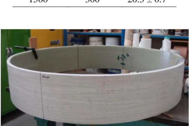
The glass/vinylester ring is manufactured by filament winding. A glass mat layer of 2.5 mm thick, positioned inside, is the first layer of the ring. Next, a stacking sequence recovers the mat. It is made of forty-two layers and contains twice more circumferential layers than axial ones. Every layer has a
thickness of approximately 0.43 mm. The dimensions of the ring are summarized in Table 1, where di
is the internal diameter, l the length and h the thickness. Figure 1 shows the experimental sample.
Table 1. Experimental sample dimensions.
di (mm) l (mm) h (mm) 1500 300 20.3 ± 0.7
M. Crozatier, S. Terekhina, F. Dau and L. Guillaumat
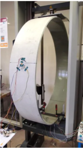
The experiment consists in a radial compression of the ring, applied with compression plates diametrically opposed (Fig. 2). The ring is clamped on the lower part. The upper plate carries out the compression through the testing machine, a Zwick 10kN.
Figure 2. Radial compression set-up.
Measurement instrumentation is used to enrich the experiment. Four rosettes are glued to the ring to follow local strains during the experiment. Rosettes 1 and 3 are glued to the inside surface of the ring, whereas rosettes 2 and 4 are located outside. In order to obtain more experimental information, two configurations in the rosettes positions relative to the loading direction are adopted (Fig. 3). Furthermore, a speckle is performed on a transverse ring edge to follow the thickness strain by an
image correlation method [9]. The ring is also instrumented by two comparators which are placed at
90° relative to the loading direction (blue rectangle), to measure the horizontal displacement of the ring.
a) b)
M. Crozatier, S. Terekhina, F. Dau and L. Guillaumat 2.2. Inverse approach
An inverse problem uses the results to get the causes. In our case, the results come from experiment and the causes are material properties. To build the inverse approach, not only a numerical model is necessary to test various causes but also an optimization process to select the best ones and to converge on a solution.
2.2.1. Numerical model
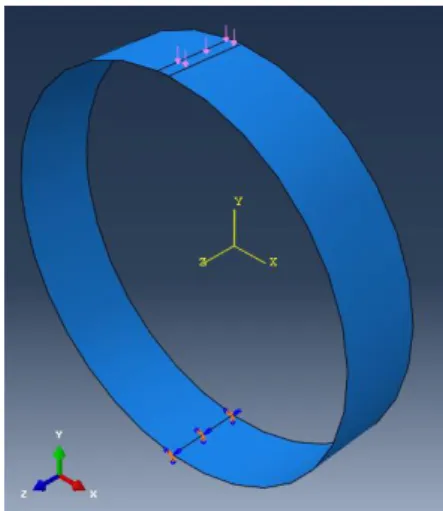
Numerical simulations by Finite Element Method (FEM) are carried out using Abaqus CAE. The
sample is modeled with shell elements (S4R). In order to reproduce the experiment, the loading is applied on the upper part of the ring via a surface pressure load, and the line diametrically opposed is clamped except the axial displacement which is not restrained. Figure 4 illustrates the boundaries conditions.
Figure 4. Numerical model: boundaries conditions.
After a convergence study, the structure is meshed with a mesh size of 10 mm. There are thus thirty elements in the ring length, and four hundred seventy eight along the circumference. The stacking sequence is reproduced by Section Shell Composite tool.
2.2.2. Particle Swarm Optimization
The aim of an optimization is to obtain a parameter set which minimizes an objective function under some constraints. Particle Swarm Optimization (PSO) is adopted [10]. It includes the initialization, the particles movement and the process stop criterion.
Firstly, PSO initializes the optimization domain with a defined swarmsize. The swarm includes all the particles. Each is associated to a parameter set.
Next, the particles move to a definite velocity. This movement is governed by Eq. 1:
vi = ω vi + 𝝋p rp (pi – xi) + 𝝋g rg (g – xi). (1)
M. Crozatier, S. Terekhina, F. Dau and L. Guillaumat
vi velocity of the particle i;
xi position of the particle i;
ω particle velocity scaling factor;
pi best known position of the particle i;
g best swarm position;
𝝋p and 𝝋g scaling factors;
rp and rg random numbers between 0 and 1.
The scaling factors ω, 𝝋p and 𝝋g are constants to define. After a sensitivity study of this parameters,
the triplet (ω; 𝝋p; 𝝋g) = (0.4; 0.6; 0.6) is retained. Indeed, a 20% gain is visible compared to the
default values (0.5).
3. Results and discussions 3.1. Elastic properties
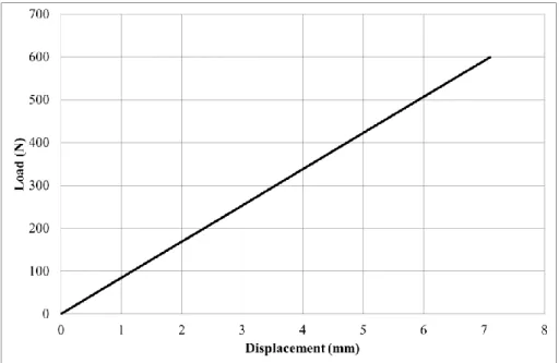
Above all, in order to determine the elastic properties, the experiment must be carried out on the elastic material domain. The loading-displacement curve obtained from a compression test is linear (Fig. 5). Furthermore, the rosettes strains return to zero at the end of the unloading. These phenomena prove that the work is led on the elastic domain.
Figure 5. Load-displacement curve from a radial compression test.
The objective function is a quadratic one, as defined in Eq. 2:
f = Σ (1 – uin / uie) ² + Σ (1 – ɛin / ɛie) ².
i i (2)
where:
uin numerical displacement;
M. Crozatier, S. Terekhina, F. Dau and L. Guillaumat ɛi
n numerical strain;
ɛi
e experimental strain.
The aim is to minimize this function. The quantities are standardized by the experimental quantities to permit a comparison. The objective function includes a sum on ten terms, four on displacement and six on strain.
A typical parameter set contains eight parameters (six characterizing a unidirectional ply of the stacking sequence and only two for the mat layer, which is supposed to be isotropic):
E1 and E2 : Young modulus;
ν12 : Poisson coefficient;
G12, G13 and G23 : shear modulus;
Emat and νmat.
Orientation 1 corresponds to the circumferential direction. Direction 2 is the axial one, and direction 3 is radial. During the optimization process, values of each parameter are taken in a physically acceptable interval to restrict the research domain.
The optimization process enables to get material properties by an inverse approach. Indeed, experiment is not enough. The digital model serves as a tool for the optimization. Many parameter sets are tested through numerical simulation. The optimization method chooses the best sets and by successive iterations, enables to reach a solution set. Table 2 presents a solution parameter set.
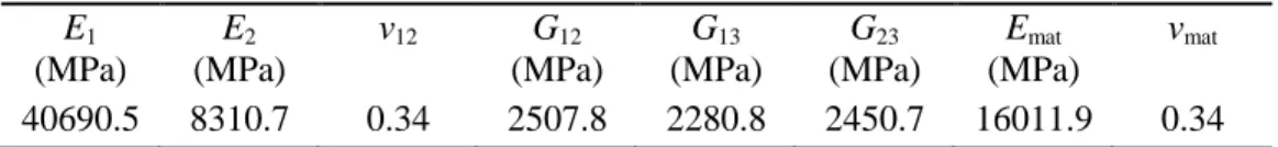
Table 2. A solution set at the end of the optimization process.
E1 (MPa) E2 (MPa) ν12 G12 (MPa) G13 (MPa) G23 (MPa) Emat (MPa) νmat 40690.5 8310.7 0.34 2507.8 2280.8 2450.7 16011.9 0.34
The circumferential modulus of the composite is governed by Eq. 3:
Ec = hs/h (2/3 E1+1/3 E2) + hm/h Emat. (3)
and is equal to 28187.2 MPa. hs is the thickness of the stacking sequence and hm is the mat thickness.
3.2. Residual manufacturing stresses
To get residual manufacturing stresses, experiments of axial cuts are led on the ring. Indeed, during this experiment, the rosettes give residual manufacturing strains. In the previous paragraph, a set of material elastic properties have been obtained. By using Hooke’s law, the evaluation of stresses becomes possible.
The experiment consists in progressive axial cuts of the ring. Indeed, during the first cut, the ring closes due to the pressure of internal compressive stresses. That is why it is decided to cut the ring step by step (each 2 mm), by extracting small sections until the ring does fold on itself anymore. Five cuts are needed. The experiment shows finally that 68.4 mm of material must be removed from the ring, in order to fully remove internal stresses. The end state of the ring is exposed on Figure 6.
M. Crozatier, S. Terekhina, F. Dau and L. Guillaumat Figure 6. Experimental sample after axial cuts: end state.
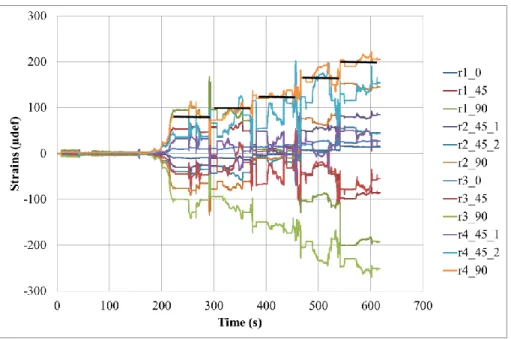
Figure 7 presents the rosettes strains versus time. For example, the curve r4_90 gives the circumferential strain measured by the circumferential gauge in the rosette 4. On this curve, each level, marked by a horizontal black line, corresponds to an axial cut.
Figure 7. Rosettes strains versus time.
The final values given by the gauges glued in the circumferential direction are summarized in Table 3. Only circumferential measurements are given since they are the most significant. It is consistent that the gauges glued in the axial directions measure low strains. The gauge r1_0 and r3_0 values are respectively 15 and 27 µdef in the final state.
Table 3. Circumferential strains at the end state.
Gauge number r1_90 r2_90 r3_90 r4_90
ɛ (µdef) -170.16 130.64 -251.76 207.06
r3
M. Crozatier, S. Terekhina, F. Dau and L. Guillaumat
These measurements enable the estimation of residual manufacturing stresses. By considering a
relaxation of 250 µdef and a circumferential modulus around 28 GPa (Ec), Hooke’s law (σ = E ɛ)
gives a circumferential compression stress of 7 MPa.
4. Conclusions
Mechanical characterization of composite laminates is essential to complete simulation in order to dimension real structures. Including the filament winding process in the elastic properties identification requires the use of curved samples during experiments. During the manufacturing process, internal stresses appear. They are due to the tension applied to the fibers during the winding. Therefore, it is necessary to involve the whole tubular structure, which is the case in this work.
An experimental protocol of radial compression is set up to realize measurements. They serve as a benchmark to carry out the optimization process using a digital model. The inverse approach, based on PSO, enables to obtain elastic properties of the unidirectional ply and the mat layer. These properties are determined via an experiment performed on a curved structure presenting residual manufacturing stresses. The characterization is thus done on the final structure, with the same stresses state that in real operating conditions.
References
[1] H. Hahn, E. Kempner and S. Lee. The stress development during filament winding of thick cylinders. Composites Manufacturing, Vol. 4(3):147-156, 1993.
[2] D. Lazuardi. Une approche du rôle des contraintes internes liées à l’élaboration sur le comportement des composites stratifiés. Université de Besançon, 1998.
[3] L. Ballère. Tolérance aux dommages par impacts de structures courbes composites – Effet d’échelles. Ecole Nationale Supérieure d’Arts et Métiers, 2008.
[4] P. Casari, F. Jacquemin and P. Davies. Characterization of residual stresses in wound composite tubes. Composites Part A: Applied Science and Manufacturing, Vol. 37(2):337-343, 2006.
[5] F. Pierron, S. Zhavoronok and M. Grédiac. Identification of the through-thickness properties of
thick laminated tubes using the virtual fields method. International Journal of Solids and
Structures, Vol. 37:4437-4453, 2000.
[6] R. Moulart, S. Avril and F. Pierron. Identification of the through-thickness rigidities of a thick laminated composite tube. Composites Part A: Applied Science and Manufacturing, Vol. 37:326-336, 2006.
[7] O. Calme, D. Bigaud and P. Hamelin. 3D braided composite rings under lateral compression.
Composites Science and Technology, Vol. 65:95-106, 2005.
[8] M. Nemat-Alla. Reproducing hoop stress-stain behavior for tubular material using lateral
compression test. International Journal of Mechanical Sciences,Vol. 45:605-621, 2003.
[9] F. Hild and S. Roux. CORRELIQ4: A software for “Finite-Element” displacement field
measurements by digital image correlation. LMT-Cachan, 2008.
[10] J. Kennedy and R. C. Eberhart. Particle swarm optimization. Proceedings of IEEE International