Paper 79 - A Rapid Procedure for Estimating the Ability of Lock
Gates to Withstand Ship Collisions
BULDGEN Loïc
a; LE SOURNE Hervé
b; RIGO Philippe
ca
FRIA PhD Student, University of Liège, Belgium; b Professor, ICAM Nantes, France;
c Professor, University of Liège, Belgium
Email (1st author): L.Buldgen@ulg.ac.be
ABSTRACT: Because of its attractiveness, the traffic on the inland waterways is expected to increase in a near future and it is to fear that the number of collisions on lock gates will follow the same trend. For this reason, it becomes more and more important to improve the crashworthiness of such structures. In this paper, we present a simplified procedure that provides quickly the approximate resistance of lock gates to ship impacts. As a first step, we briefly describe the analytical procedure leading to the evaluation of the resistance. Then, in the second part of the paper, we confront our results to those obtained through finite elements simulations.
1 INTRODUCTION
It is frequent for ships travelling on inland waterways to pass across lock structures. During this critical operation, some collisions may arise, in particular when vessels are travelling too fast and do not have enough time to stop before reaching the gate.
Unfortunately, for the two following main reasons, it is to fear that such accidents will be more likely in the future:
1) The inland navigation is increasing all over the world, so it is clear that the collision probability is also becoming more important.
2) The vessels are becoming larger, which means that maneuvering them is also more difficult, especially in confined places like lock chambers. As a consequence, in a near future, it is reasonable to believe that lock gates are going to suffer more frequent impacts involving larger ships. This will oblige engineers to think for more crashworthy structures. For assessing the ability of withstanding to collisions, it is of current practice to resort to finite elements software, but this may not be convenient when pre-designing a lock gate. The main reason is that this method rapidly becomes time expensive, especially if an iterative process is desired for optimization purposes.
As a consequence, it is essential to provide engineers with some other tools allowing them for a
quick estimation of the crashworthiness
characterizing their structures. This is precisely the goal of this paper, in which we present a simplified procedure leading to a rapid prediction of the resistance of lock gates with a simple plating and a basic reinforcing system.
It is worth mentioning that our intention is just to give a global insight into the simplified methodology and to show how it could be used during the pre-design phase. But it is not our purpose to provide here complicated developments and to go into a very detailed description of the mathematical procedure.
2 GENERAL OVERWIEW
2.1 Global and local deforming modes
In this simplified approach, we assume that the striking vessel is perfectly rigid, which implies that its initial kinetic energy has to be entirely dissipated by the deformations of the gate. Such an assumption is rather conservative, as in reality, the ship will also be affected during the collision. So we are in fact overestimating the damages to the structure.
In order to establish an analytical procedure providing a quick evaluation of the collision resistance, we will first suppose that the gate may deform in two different manners during an impact:
1) The local deforming mode, which is associated to a localized indentation of the striking vessel. During this process, the major part of the structure is not affected by the impact and the penetration of the vessel is mainly allowed by the crushing of some elements in a confined area. 2) The global deforming mode, which is associated
to an overall deformation of the gate. In this case, the striking vessel keeps moving forward by involving displacements on the entire gate. These concepts are roughly illustrated on Figure 1, which shows the deflection of a miter gate collided on one leaf. We see that some confined deformations occur near the impact point (see region A on Figure 1), which may be directly related to the local deforming mode. Nevertheless, on the top view of Figure 1, it is apparent that an overall bending motion of the struck structure is also activated. This may be undoubtedly associated to the global sequence. It is important to distinguish between these two modes, as they influence the behavior of the gate. This phenomenon has already been investigated in references [1] to [4].
A B A Leaf 1 Leaf 2 Leaf 1 Leaf 2
Figure 1: Global and local deforming modes for a miter gate impacted on one leaf [3].
At the beginning of the collision process, it is clear that the gate will be affected in a quite small region, which means that the local deforming mode is first activated. But as the ship is moving forward, a more important part of the structure will be progressively involved in the resisting process. For this reason, there must be a switch from the local to the global mode, and we need to know when this transition is likely to occur.
2.2 Transition between the two modes
For a given penetration δ of the striking vessel
into the gate, we can first assume that the structure
is withstanding through a local mode. The
resistance in this case is denoted by Ploc and may
be evaluated for each value of δ. But on the other
hand, it is also possible to imagine that the gate is withstanding through a global mode, for which
another value of the resistance Pglob may be
derived.
The basic idea to get the total collision resistance
P is to suppose that it is always minimal. In other
words, P will be taken as the minimum between Ploc
and Pglob, as depicted on Figure 2. On this picture,
we see that during the first phase, we have Ploc <
Pglob, which implies that P = Ploc, so we assume that
the gate is mainly resisting through its local deforming mode.
Nevertheless, as the penetration is getting larger, it is finally easier for the ship to progress by imposing an overall motion to the gate, instead of crushing some very localized structural elements. In
this second phase, we have Ploc > Pglob, which
means that P = Pglob, so the gate is this time
supposed to withstand through its global deforming mode.
1
2
δ
δ
tP
P
locP
globFigure 2: Evolution of the global and local
resistances with the penetration δ [4].
On Figure 2, we see that Ploc = Pglob for a
particular penetration δt. This corresponds to the
theoretical indentation for which there is a transition between the local and the global modes.
Consequently, during the first phase where δ < δt,
we have P = Ploc, while P = Pglob during the second
phase where δ > δt.
From all the previous considerations, it transpires that the analytical derivation of P may be achieved by solving two different problems, which consist in
finding two coherent closed-form solutions for Ploc
and Pglob.
3 LOCAL RESISTANCE
The resistance in the local deforming mode is evaluated by dividing the gate into N large structural components called “super-elements”. Each of them is characterized by a law giving its individual
As announced in the introduction, this paper is mainly concerned with simple lock gates. These ones are known for having only one plating, reinforced by orthogonal horizontal and vertical stiffeners (such as miter or lifting gates for example). If we want to decompose entirely this kind of structure into various components, then we need to introduce at least four different types of super-elements (Figure 3):
1) Type A: this type of super-element is used to represent plating elements bounded by two vertical and two horizontal stiffeners and submitted to an out-of-plane impact.
2) Type B: this type of super-element is used to model portions of vertical stiffeners delimited by two horizontal ones. For such elements, it is worth noting that the collision may not appear on one of their intersection. In other words, they are always impacted somewhere between the two delimiting horizontal stiffeners (otherwise they have to be treated as a type C).
3) Type C: this type of super-element is introduced to treat the impact occurring on the intersection between horizontal and vertical girders.
4) Type D: type D is the same as type C, but this time it is applicable to the portions of horizontal stiffeners bounded by two vertical ones. Here again, the impact may not take place on their intersections, unless they are considered as a type C.
For each of the four different types introduced here above, it is possible to find a closed-form expression relating the individual resistance of the super-element to the indentation. This can be achieved by resorting to the upper-bound theorem. As this operation is quite fastidious, it is not reported here, but additional information on this topic may be easily found in the literature (see references [5] to [9] for example).
Each of the N super-elements modeling the gate is characterized as being of type A, B, C or D. An
analytical law giving their individual resistance Pi
during the impact is now available. In order to
progress in the derivation of local resistance Ploc, we
will further assume that the two following assumptions are holding:
1) A super-element remains inactive (Pi = 0) as long
as a geometrical contact is not established with the striking bow.
2) The deformations taking place in one super-element does not affect the surrounding other components. Consequently, each element is supposed to be totally decoupled from the others.
The direct implication of the two previous
hypotheses is that the local resistance Ploc may be
simply obtained by summing up all the individual
contributions Pi coming from the activated
super-elements. We have therefore the following relation:
(1)
So finally, we see through equation (1) that it is possible to find a broad estimation of the local resistance simply by applying the super-elements method. The next step now is to perform the same work for the global deforming mode.
Type A
Type B
Type C
Type D
Figure 3: The four different types of super-elements used to decompose a basic stiffened structure [4]. 4 GLOBAL RESISTANCE
The resistance Pglob in the global mode is derived
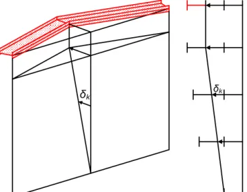
under the hypothesis that the gate is forced into an overall motion, where the bending effects are preponderant. This is roughly depicted on Figure 4, which shows the global deformation pattern for a gate resting against a sill. During such a movement, it is clear that the main contribution to the resistance is coming from the horizontal girders and not really from the vertical stiffeners.
As a consequence, if the structure is reinforced by M horizontal girders, then it may be seen as a set of M independant beams simply supported by the lock walls. These beams are bent in their plane and
submitted to an individual displacement δk (Figure
5). By postulating simple geometrical relations, it is
possible to express these δk as functions of the ship
penetration δ.
δ
Figure 4: Global bending motion for a gate resting against a sill.
Of course, when it is forced to move, each of the
M girders is opposing an individual resistance Pk, which can be simply evaluated by resorting to the classical rules of the elastic-plastic bending of beams.
δk
δk
Figure 5. Individual bending of the horizontal girders in their plane.
As each of the M horizontal girders is assumed to be independent from all the others, we can calculate
here again the total global resistance Pglob simply by
summing up all the contributions Pk. Doing so, we
get:
(2)
So finally, we see through equation (2) that it is quite easy to get an estimation of the global resistance just by applying the classical theory of beams.
5 TOTAL RESISTANCE
Now that the local and global resistances have been derived, it is quite easy to get the total one P
by considering the minimal value between Ploc and
Pglob for each value of the penetration δ. Doing so,
we finally obtain a curve giving P as a function of δ.
For a given value of the penetration, if we integrate this curve, we get the following total deformation energy:
(3)
where x is simply an integration variable. Furthermore, under the hypothesis that the striking vessel is perfectly rigid, it is clear that the ship will stop moving forward when all its initial kinetic
energy Ecin has been dissipated by the gate. In other
words, the maximal penetration δf will be reached
when:
(3)
For δ = δf, the ship is stopped and the collision
process is stabilized. It is worth noting that Ecin may
be easily calculated by considering the total mass and the initial velocity of the striking vessels. These two parameters may be deduced from the class of the waterway where the lock is positioned, but they can also be directly provided by the client. Engineers therefore know the total energy they have to account for when designing their structures against ship impact.
6 NUMERICAL VALIDATION
To validate the simplified analytical approach exposed here over, we will now apply it to different lock gates. The aim of this section is to compare the
curves P(δ) obtained by the present simplified
method with the ones provided by simulating the
collision with the finite element software LS-DYNA.
In this section, we will consider two different examples. The first one is a lifting gate, while the
second one is a miter gate. Additional information about these applications may be found in references [1] and [4] where they have already been presented.
The finite elements model of the striking vessel used for simulating these collisions is depicted on Figure 6. To have better contact conditions, we see that the mesh is coarser in the region located near the impact point. The ship is assumed to have a displacement of 4000 tons and an initial velocity of 2 m/s.
Figure 6. Finite elements model of the striking
vessel used for the numerical simulations with LS
-DYNA.
The two gates are assumed to be made of classical steel, with a Young modulus of 210 GPa and a yield stress of 235 MPa.
6.1 Example 1: lifting gate
In this first example, we consider a lifting gate made of a single plating reinforced by five horizontal girders and six vertical frames. Some additional smaller stiffeners are also present, mainly to prevent the plate from buckling. The principal dimensions of the structure are depicted on Figure 7.
X Z Y X Z Z Y 6 6 c m 2.3 m 4.8 m 7.8 m 13.1 m 2 .6 2 m 5 .2 4 m 7 .8 6 m 1 0 .4 8 m 1 3 .1 m 1 m 1 m
Figure 7. Main geometrical dimensions of the lifting gate [1].
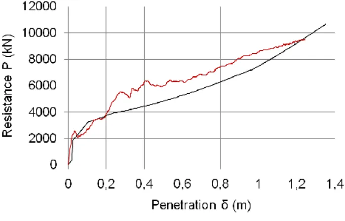
Figure 8 shows the results obtained after a finite elements simulation of the collision. The resistance given by the present approach is also represented on Figure 8. As it can be seen, the agreement between the two curves is satisfactory for this lifting gate example.
Figure 8. Comparison of the resistance curves P(δ)
obtained by LS-DYNA (numerical) and by the present
approach (analytical) for the lifting gate example [1]. 6.2 Example 2: miter gate
For the second example, we consider this time the case of miter gate. The right leaf is depicted on Figure 9, where its main geometrical dimensions are also indicated. The structure is made of a plating, reinforced by five horizontal girders and three vertical frames. A sill is present at the bottom of the chamber. At the middle of the lock, the contact between the two leaves is provided through five very rigid contact blocks. Such elements are also present on the lateral sides to realize the contact between the gate and the walls. Some cables are added to impose coherent support conditions.
Central contact block Frame Plating Sill Lateral contact block 19.5° Lock wall 2.35 3.5 3.5 2.35 1.5 2.53 2.70 3.83 1.24 Frame Girder Plating Sill
Figure 9. Main geometrical dimensions (m) of the miter gate [4].
The results obtained for this miter gate are depicted on Figure 10. Here again, we can see that the curve given by the simplified methodology is in quite good agreement with the one obtained by finite elements simulations.
0 2000 4000 6000 8000 10000 12000 14000 16000 0 0,1 0,2 0,3 0,4 0,5 0,6 0,7 0,8 0,9 R e s is ta n c e P ( k N ) Penetration δ (m) Analytical Numerical
Figure 10. Comparison of the resistance curves P(δ)
obtained by LS-DYNA (numerical) and by the present
approach (analytical) for the miter gate example [4]. 7 NUMERICAL VALIDATION
In this paper, we briefly expose a simplified analytical procedure allowing for a quick estimation of the crashworthiness of a lock gate. We first provide some very general explanations on the way to estimate the resistance in both the local and global modes, but it is not our purpose to go into deep mathematical developments. After that, as a kind of validation, we propose two application examples. The first one is dealing with the collision on a lifting gate, while the case of an impact on a miter gate is treated in the second one.
For the two examples, the present simplified method is found to give quite satisfactory results in a very short time, which is precisely the main advantage of this new procedure. We believe that such a tool may be very useful for engineers that have to pre-design lock gates, as they only need to have some approximate results in a very short time. REFERENCES
[1] Buldgen L., Le Sourne H., Rigo P., 2012, “Simplified Analytical Method for Estimating the Resistance of Lock Gates to Ship Impacts”, Journal of Applied Mathematics, Vol. 2012. [2] Buldgen L., Le Sourne H., & Rigo P., 2013,
"Fast Strength Assessment of Mitre Gates to
Ship Impact. International Journal of
Crashworthiness.
[3] Le Sourne H., Rodet J.C., Clanet C., 2002,
“Crashworthiness Analysis of a Lock Gate Impacted by Two River Ships”, International
Journal of Crashworthiness, Vol. 7, pp.
371-396.
[4] Buldgen L., Le Sourne H., Rigo, P., 2013, "A Simplified Procedure to Assess the Strength of a Ship Impacting a Lock Miter Gate",
Proceedings of the ASME 2013 32nd International Conference on Ocean, Offshore and Arctic Engineering.
[5] Zhang S.M., 1999, “The Mechanics of Ship
Collisions”, PhD. thesis, Department of Naval
Architecture and Offshore Engineering,
Technical University of Denmark.
[6] Hong L., Amdahl J., 2008, “Crushing
Resistance of Web Girders in Ship Collision and Grounding, Marine Structures, Vol. 21, pp. 374-401.
[7] Simonsen B.C., 1998, “Ship Grounding on Rock
– I. Theory”, Marine Structures, Vol. 10, pp. 519-562.
[8] Simonsen B.C., Ocakli H., 1999, “Experiments and Theory on Deck Girder Crushing”,
Thin-Walled Structures, Vol. 34, pp. 195-216.
[9] Amdahl J., 1983, Energy Absorption in Ship-Platform Impact, PhD. thesis, Department of Marine Technology, Norwegian University of Science and Technology.
![Figure 2: Evolution of the global and local resistances with the penetration δ [4]](https://thumb-eu.123doks.com/thumbv2/123doknet/6568521.177571/2.892.69.419.581.868/figure-evolution-global-local-resistances-penetration-δ.webp)
![Figure 3: The four different types of super-elements used to decompose a basic stiffened structure [4]](https://thumb-eu.123doks.com/thumbv2/123doknet/6568521.177571/3.892.485.817.381.913/figure-different-types-super-elements-decompose-stiffened-structure.webp)