To link to this article : DOI:
10.1016/j.elecom.2016.08.013
URL :
http://dx.doi.org/10.1016/j.elecom.2016.08.013
This is an author-deposited version published in:
http://oatao.univ-toulouse.fr/
Eprints ID: 16644
O
pen
A
rchive
T
oulouse
A
rchive
O
uverte (
OATAO
)
OATAO is an open access repository that collects the work of Toulouse
researchers and makes it freely available over the web where possible.
To cite this version: Kisu, Kazuaki and Iwama, Etsuro and Naoi, Wako
and Simon, Patrice and Naoi, Katsuhiko Electrochemical kinetics of
nanostructure LiFePO4/graphitic carbon electrodes. (2016)
Electrochemistry Communications, vol. 72. pp. 10-14. ISSN 1388-2481
Any correspondence concerning this service should be sent to the repository administrator:
[email protected]
Electrochemical kinetics of nanostructure LiFePO
4
/graphitic
carbon electrodes
Kazuaki Kisu
a,b, Etsuro Iwama
a,b, Wako Naoi
c, Patrice Simon
b,d,e, Katsuhiko Naoi
a,b,c,f,⁎
aDepartment of Applied Chemistry, Tokyo University of Agriculture & Technology, 2-24-16 Naka-cho, Koganei, Tokyo 184-8588, Japan bInstitute of Global Innovation Research, Tokyo University of Agriculture and Technology, 2-24-16 Naka-cho, Koganei, Tokyo 184-8588, Japan cDivision of Art and Innovative Technologies, K & W Inc., 1-3-16-901 Higashi, Kunitachi, Tokyo 186-0002, Japan
dUniversité Paul Sabatier Toulouse III, Institut Carnot CIRIMAT, UMR 5085, 118 route de Narbonne, F-31602 Toulouse Cedex 9, France eRéseau sur le Stockage Electrochimique de l'Energie (RS2E), FR CNRS 3459, France
fAdvanced Capacitor Research Center, Tokyo University of Agriculture & Technology, 2-24-16 Naka-cho, Koganei, Tokyo 184-8588, Japan
a b s t r a c t
Lithium cation insertion/deinsertion reaction kinetics in a LiFePO4(LFP)/graphitic carbon composite material
were electrochemically studied with a cavity microelectrode (CME). The LFP/graphitic carbon composite has a core LFP (crystalline/amorphous)/graphitic carbon shell structure. In the crystalline and amorphous LFP phase, different reaction mechanisms were observed and characterized. While the reaction mechanism in the crystalline LFP phase is controlled by Li+ diffusion, the amorphous LFP phase shows a fast, surface-controlled,
pseudocapacitive charge-storage mechanism. This pseudocapacitive behavior is extrinsic in origin since it comes from the presence of Fe3+defects in the structure. These features explain the ultrafast performance of
the material which offers interesting opportunities as a positive electrode for assembling high power and high energy hybrid supercapacitors.
Keywords:
Defective lithium iron phosphate Core/shell structure Pseudocapacitive behavior Ultrafast performance Hybrid supercapacitor Cavity microelectrode 1. Introduction
Electric double-layer capacitors (EDLCs) are energy storage devices offering extremely fast charging-discharging characteristics, remark-able stability and long cycle life[1]. Thus, EDLCs are mainly used in ap-plications where instant power is required for short time[2]. However, the low energy density of EDLCs still limits their range of applications. A promising route to increase the energy density of supercapacitors is designing hybrid supercapacitors where an activated carbon electrode is combined with a fast, faradic charge storage electrode [3]. Pseudocapacitive materials with fast redox reactions confined at the surface of materials have been proposed as the faradic electrode, such as transition metal oxides[4–7]or two-dimensional transition metal carbides[8,9]. However, most of these pseudocapacitive materials oper-ate in aqueous electrolytes, thus limiting their practical interest for high-energy supercapacitor applications. V2O5[10], H2Ti3O7[11,12] and TiO2(B) [13,14] were among the first materials showing pseudocapacitive behavior in Li+containing nonaqueous electrolytes. Although high capacity (200 mAh g− 1) was obtained, cyclability and power performance are still a concern[15]. More recently, the fast pseudocapacitive behavior of orthorhombic Nb2O5was identified in
nonaqueous electrolyte, which was explained by a Li+ pseudo-interca-lation mechanism[16]. The high discharge rates (up to 1000 C) make this material interesting as a negative electrode for hybrid devices[17]. Recently, we used the ultracentrifugation technique to prepare a LiFePO4 (LFP)/graphitic carbon composite material. This material showed ultrafast charge/discharge rates (35 mAh g− 1at 300 C), compa-rable to activated carbons used in EDLCs[18]. LFP/graphitic carbon com-posite has a core LFP (crystalline/amorphous)/graphitic carbon shell structure that offers both high reversibility and high rate capability. Un-like conventional LFP where Li+intercalation is achieved at constant potential through a two-phase reaction mechanism, the galvanostatic charge/discharge profile of the composite showed different electro-chemical signatures. Three various regions were observed: one plateau at a constant potential of 3.4 V corresponding to the crystalline LFP phase and two sloping profiles below and above 3.4 V corresponding to amorphous LFP containing Fe3+defects and graphitic carbon phases, respectively[18]. The Li+
diffusion coefficient in the sloping potential region of the amorphous LFP phase (10− 11cm2s− 1) was found to be two orders of magnitude higher than that of crystalline LFP core phase (10− 13cm2s− 1). Such a high Li+diffusivity was assumed to be mainly responsible for the high rate capability of the composite but the charge storage mechanisms in the different potential regions have still to be understood. In this paper, the electrochemical kinetics of LFP/graphitic carbon composite was investigated using the cavity microelectrode
⁎ Corresponding author.
(CME) technique[19]. We identified two different behaviors and kinetic regimes. The Li+intercalation in the core crystalline LFP phase is a diffu-sion-limited process while a surface charge storage pseudocapacitive mechanism drives the kinetics in the sloping potential region. This fast, extrinsic pseudocapacitive process originating from the presence of Fe3 +defects in the amorphous LFP phase[18]explains the high power performance of the LFP/graphitic carbon composite.
2. Experimental
The synthesis procedure of the LFP/graphitic carbon composite using ultracentrifugation technique[20]was reported elsewhere[18]. The electrochemical tests with CME were performed at room temperature in a mixture of ethylene carbonate (EC) and diethyl carbonate (DEC) containing 1.0 M of LiPF6, which was purchased from KISHIDA CHEMCAL Co., Ltd. (battery grade). The CME consists of a thin platinum wire (Φ = 60 μm) with a cavity of 30 μm Φ and 40 μm deep sealed in a glass[19].
3. Results and discussion
Fig. 1a (inset) shows a schematic of the prepared LFP composite ma-terial[18]. The core of the composite contains a nanocrystalline LFP phase (core 1) surrounded by an amorphous LFP phase containing
Fe3+defect (core 2).Fig. 1a shows the cyclic voltammogram (CV) for LFP/graphitic carbon composite in a two-electrode cell at a low scan rate of 0.1 mV s− 1
in the 2.0 V–4.2 V potential range. The set of redox peaks (peak A and A′) observed at 3.4 V vs. Li/Li+corresponds to the core crystalline LFP phase. Below 3.4 V, the CV is characterized by the presence of two redox waves at about 3 V (peak B and B′), leading to a symmetric, capacitive-like CV signature where the charge changes with the applied potential. Previous in-situ XAFS measurements have shown a continuous change in the oxidation state of Fe in this potential range[18]. Accordingly, the electrochemical signature can be assigned, in a first approach, to a pseudocapacitive behavior. This pseudocapacitive behavior is extrinsic in origin, since it is related to the presence of Fe3+defects in the structure[15,21,22]. The capacitive current observed below 2.5 V and beyond 3.4 V corresponds to the dou-ble-layer capacitance of the graphitic carbon shell, since no change in the oxidation state of Fe was observed[18]; it accounts for about 25% of the total capacity.
The LFP/graphitic carbon composite was studied using a CME in a three-electrode mode configuration, at various scan rates from 10 to 1000 mV s− 1(Fig. 1b). Even at 1000 mV s− 1, both set of peaks A and B can be observed despite a merging of two peaks at such high scan rates.Fig. 1c shows the changes of the peak potentials (A and A′) as a function of the scan rate. The peak separation (Epa- Epc) is 132 mV at 1 mV s− 1and increases with the scan rate with a slope of about
Fig. 1. (a) Cyclic voltammogram of LiFePO4/graphitic carbon at 0.1 mV s−1in 1 M LiPF6EC + DEC (vol 1:1) electrolyte using coin-type-cell configuration, where Li foil was used as a
negative electrode. (b) Cyclic voltammograms of LiFePO4/graphitic carbon at 10, 20, 50, 100, 200, 500, 1000 mV s−1in same electrolyte using cavity microelectrode. A1 cm2rolled
platinum foil and a piece of lithium metal were used as a counter and reference electrodes, respectively. (c) Changes of the anodic (orange) and cathodic (blue) peak potentials, and mean peak potential (=(Epa+ Epc)/2, black) as a function of the scan rate. (d) Change of the peak separation (Epa- Epc) as a function of the scan rate.
65 mV per decade in the 1–20 mV s− 1potential scan rate range. The peak separation for a quasi-reversible reaction is 60/αn mV for each ten-fold increase in scan rate, with α the charge transfer coefficient, v the scan rate and n the number of exchanged electrons. LFP/graphitic com-posite can be considered as a quasi-reversible system, with a α value close to 0.92. Then, the peak separation increases with the sweep rate (beyond 400 mV for v 100 mV s− 1), as shown inFig. 1d. This increase
is due to the decrease of the αn term such as expected at higher scan rates[19].Fig. 1c also shows that the mean peak potential, i.e., the average value between anodic and cathodic peaks, is constant at 3.42 V vs. Li/Li+
in the 0.1–500 mV s− 1sweep rate range, in agreement with previous results[23]. On the other hand, at the highest scan rate of 1000 mV s− 1, the mean peak potential drastically decreases to 3.3 V vs. Li/Li+
; here, the merging of reduction peaks A′ and B′ makes difficult the
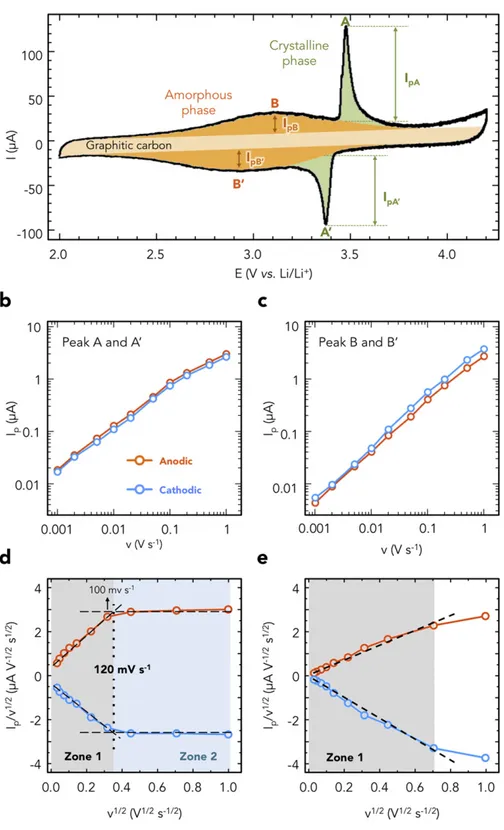
Fig. 2. (a) Deconvolution of the cyclic voltammogram of LFP/graphitic carbon using a Gaussian-type function for the crystalline LFP phase (green), amorphous LFP phase (orange) and graphitic carbon (light yellow). These peak currents were corrected from the double-layer capacitive contribution of the graphitic carbon shells. Plots of the anodic (orange) and cathodic (blue) peak intensities for peak A (b) and peak B (c) as a function of the scan rate in a logarithm scale. Plots of Ip/v1/2vs. v1/2for peak A (d) and peak B (e) obtained at 10
determination of the peak positions. The peak current density for the set of peaks A and B was obtained from the deconvolution of the CVs, as shown inFig. 2a. For a two-phase charge transfer process, such as for the (LFP)/(FP) system, the Li+extraction/insertion leads to a current peak whose intensity depends on the scan rate (Eq.(1))[24]:
Ip¼ avb ð1Þ
where Ipis the peak intensity, v the scan rate in V s− 1, a and b are adjust-able coefficients.
For the analysis, we assume that currents arising from bulk interca-lation processes follow semi-infinite linear diffusion kinetics and there-fore will vary as v1/2(b = 0.5; diffusion-controlled current). In contrast, currents resulting from surface charge storage processes will have a capacitive response and vary linearly with v (b = 1.0; chargetransfer -controlled current). For a Nernstian (reversible) system, both anodic (A) and cathodic peak (A′) intensities would show the same magnitude. The difference in the peak current intensity (A/A′) inFig. 1a has been as-cribed to the diffusion of Li+in different electrochemical environments during the two-phase reaction[19,25].
Fig. 2b shows the changes of the A/A′ peak currents vs. the scan rate in a logarithmic scale. Despite a slight change of the slope observed at ca. 10 mV s− 1, the average b coefficients calculated from Eq.(1)were 0.76 for both the anodic and cathodic processes. Previous study showed that LFP crystalline two-phase reaction has b coefficients of 0.53 and 0.55 for the anodic and cathodic processes, respectively[19]. However, the dif-ference in the crystalline LFP particle size (~20 nm) and in the structure of the present LFP/graphitic carbon composite could explain this differ-ence.Fig. 2c shows the changes of the peak current for peak B and B′ de-pending on scan rates. The calculated average b coefficients were 0.97 for the anodic and cathodic processes. This means that the peak B (amorphous LFP) characteristic is associated with a fast, nondiffusion-limited, surface reaction such as observed for pseudocapacitive mate-rials. Differently from MnO2 [4,5], TiO2 [6] or Nb2O5 [16], this pseudocapacitive behavior is extrinsic in origin, since it is related to the presence of Fe3+defects in the structure[15,21,22].
To get further insights on the electrochemical reaction kinetics in the two different potential ranges (peaks A and B), we divided the total cur-rent into two contributions such as proposed by Dunn's group[15,16,26, 27]. One part of the current comes from semi-infinite diffusion process-es and changprocess-es with v1/2and the other is related to capacitive (surface) processes and varies linearly with v. Therefore, the current response (I) at a fixed potential (V) can be described as the combination of these two separate mechanisms (Eq.(2)):
Ip=v1=2¼ k1v1=2þ k2 ð2Þ
where Ip, and v stand for the peak intensity and the scan rate in V s− 1, respectively. k1coefficient is associated with a fast, non-Li+ diffusion-limited surface process, while k2defines Li+diffusion-limited faradic re-action[19]. Using Eq.(2), it becomes possible to determine the process governing the reaction kinetics by calculating the ratio k1/k2.Fig. 2d shows the Ip/v1/2vs. v1/2plots from 1 to 1000 mV s− 1for peaks A and A′. Considering Eq.(2), k1can be calculated from the slope of the plot while k2is defined by the value at v1/2= 0. The plots can be divided into two regions (dotted line inFig. 2d): a linear region (zone 1) at scan rates below 120 mV s− 1, and a nearly flat region (zone 2). Zone 1 shows high k1contribution (N94%) to the total of k1+ k2, which evi-dences a non-Li+
diffusion-limited reaction of peak A and A′ at a slow scan rate. Indeed, below 120 mV s− 1, the scan rate is small enough so that the charge transfer controls the kinetics of the electrochemical re-action. The maximum scan rate of the zone 1, (120 mV s− 1) is higher value compared to the other reported value for crystalline LFP (5 mV s− 1)[19]. A first explanation for this kinetic enhancement lies in the mutual effect between the crystalline and amorphous LFP phases, where high Li+diffusivity in the outer amorphous phase helps Li+
diffusion/penetration into the inner crystalline phase. Another reason-able explanation is the smaller particle size of crystalline core (~ 20 nm) compared to the reported LFP (140 nm), which increases the ratio of the surface to the LFP bulk.Fig. 2e shows the same Ip/v1/2 vs. v1/2
plots in the 2.0–3.2 V potential range for peak B and B′. Unlike for peak A and A′, the plot shows a linear change in the whole region (zone 1) which evidences a non-Li+diffusion-limited reaction of peak B. The decrease of the current at 1000 mV s− 1comes from the difficulty to identify the peak B at such high scan rate. In this region, the pseudocapacitive contribution reaches 98% of the total current.
This study clearly confirms the ultrafast performance of the LFP/gra-phitic carbon composite. The fast electrochemical response of the crys-talline LFP is combined with the ultrafast performance of amorphous LFP containing Fe3 +defects, leading to power capability similar to that of activated carbon in EDLC[18]. Such structuration appears to be highly suitable for designing high power materials for hybrid supercapacitor applications.
4. Conclusion
Pseudocapacitive behavior of LFP (core)/graphitic carbon (shell) composite was evaluated using CME which allows focusing on the ki-netic properties of the material on a broad range of scan rate. The elec-trochemical analysis showed two different behaviors and kinetic regimes in the core LFP (amorphous and crystalline). A surface charge storage pseudocapacitive mechanism drives the kinetics in the amor-phous LFP phase containing Fe3 +defects, while the Li+intercalation in the core crystalline LFP phase is a diffusion-limited process at a high scan rate (N120 mV s−1). These results propose new routes for design-ing high power materials to assemble high energy density hybrid supercapacitors.
Acknowledgement
This study was supported in part by Institute of Global Innovation Research Organization in TUAT. This work was supported by JSPS KAKENHI grant numbers JP25249140, JP15H06193.
Reference
[1] J.R. Miller, P. Simon, Materials science. Electrochemical capacitors for energy man-agement, Science 321 (2008) 651–652.
[2] P. Simon, Y. Gogotsi, Materials for electrochemical capacitors, Nat. Mater. 7 (2008) 845–854.
[3] M. Salanne, B. Rotenberg, K. Naoi, K. Kaneko, P.L. Taberna, C.P. Grey, B. Dunn, P. Simon, Efficient storage mechanisms for building better supercapacitors, Nat. Ener-gy 1 (2016) 16070.
[4] H.Y. Lee, V. Manivannan, J.B. Goodenough, Electrochemical capacitors with KCl elec-trolyte, Comptes Rendus de l'Académie des Sciences - Series IIC - Chemistry 2 (1999) 565–577.
[5] M. Toupin, T. Brousse, D. Bélanger, Charge storage mechanism of MnO2electrode used in aqueous electrochemical capacitor, Chem. Mater. 16 (2004) 3184–3190.
[6] Y. Zhu, X. Ji, C. Pan, Q. Sun, W. Song, L. Fang, Q. Chen, C.E. Banks, A carbon quantum dot decorated RuO2network: outstanding supercapacitances under ultrafast charge and discharge, Energy Environ. Sci. 6 (2013) 3665–3675.
[7] J. Wang, J. Polleux, J. Lim, B. Dunn, Pseudocapacitive contributions to electrochemi-cal energy storage in TiO2(anatase) nanoparticles, J. Phys. Chem. C 111 (2007) 14925–14931.
[8] M.R. Lukatskaya, O. Mashtalir, C.E. Ren, Y. Dall'Agnese, P. Rozier, P.L. Taberna, M. Naguib, P. Simon, M.W. Barsoum, Y. Gogotsi, Cation intercalation and high volumet-ric capacitance of two-dimensional titanium carbide, Science 341 (2013) 1502–1505.
[9] C. Zhang, M. Beidaghi, M. Naguib, M.R. Lukatskaya, M.-Q. Zhao, B. Dyatkin, K.M. Cook, S.J. Kim, B. Eng, X. Xiao, D. Long, W. Qiao, B. Dunn, Y. Gogotsi, Synthesis and charge storage properties of hierarchical niobium pentoxide/carbon/niobium car-bide (MXene) hybrid materials, Chem. Mater. 28 (2016) 3937–3943.
[10] W. Dong, D.R. Rolison, B. Dunn, Electrochemical properties of high surface area va-nadium oxide aerogels, Electrochem. Solid-State Lett. 3 (2000) 457–459.
[11] G.-N. Zhu, C.-X. Wang, Y.-Y. Xia, Structural transformation of layered hydrogen trititanate (H2Ti3O7) to TiO2(B) and its electrochemical profile for lithium-ion inter-calation, J. Power Sources 196 (2011) 2848–2853.
[12] E. Morgado Jr., P.M. Jardim, B.A. Marinkovic, F.C. Rizzo, M.A. de Abreu, J.L. Zotin, A.S. Araujo, Multistep structural transition of hydrogen trititanate nanotubes into TiO2-B
nanotubes: a comparison study between nanostructured and bulk materials, Nano-technology 18 (2007) 495710.
[13] K. Naoi, T. Kurita, M. Abe, T. Furuhashi, Y. Abe, K. Okazaki, J. Miyamoto, E. Iwama, S. Aoyagi, W. Naoi, P. Simon, Ultrafast nanocrystalline-TiO2(B)/carbon nanotube hyperdispersion prepared via combined ultracentrifugation and hydrothermal treatments for hybrid supercapacitors, Adv. Mater. 28 (2016) 6751–6757.
[14]M. Zukalova, M. Kalbac, L. Kavan, I. Exnar, M. Graetzel, Pseudocapacitive lithium storage in TiO2(B), Chem. Mater. 17 (2005) 1248–1255.
[15] V. Augustyn, P. Simon, B. Dunn, Pseudocapacitive oxide materials for high-rate elec-trochemical energy storage, Energy Environ. Sci. 7 (2014) 1597.
[16] J.W. Kim, V. Augustyn, B. Dunn, The effect of crystallinity on the rapid pseudocapacitive response of Nb2O5, Adv. Energy Mater. 2 (2012) 141–148. [17] V. Augustyn, J. Come, M.A. Lowe, J.W. Kim, P.-L. Taberna, S.H. Tolbert, H.D. Abruna, P.
Simon, B. Dunn, High-rate electrochemical energy storage through Li+intercalation pseudocapacitance, Nat. Mater. 12 (2013) 518–522.
[18]K. Naoi, K. Kisu, E. Iwama, S. Nakashima, Y. Sakai, Y. Orikasa, P. Leone, N. Dupre, T. Brousse, P. Rozier, W. Naoi, P. Simon, Ultrafast charge-discharge characteristics of a nanosized core-shell structured LiFePO4material for hybrid supercapacitor appli-cations, Energy Environ. Sci. 9 (2016) 2143–2151.
[19] J. Come, P.L. Taberna, S. Hamelet, C. Masquelier, P. Simon, Electrochemical kinetic study of LiFePO4using cavity microelectrode, J. Electrochem. Soc. 158 (2011) A1090–A1093.
[20] K. Naoi, W. Naoi, S. Aoyagi, J.-i. Miyamoto, T. Kamino, New generation “nanohybrid supercapacitor”, Acc. Chem. Res. 46 (2012) 1075–1083.
[21] P. Simon, Y. Gogotsi, B. Dunn, Materials science. Where do batteries end and supercapacitors begin? Science 343 (2014) 1210–1211.
[22] R. Amisse, M.T. Sougrati, L. Stievano, C. Davoisne, G. Dražič, B. Budič, R. Dominko, C. Masquelier, Singular structural and electrochemical properties in highly defective LiFePO4powders, Chem. Mater. 27 (2015) 4261–4273.
[23] A.K. Padhi, K.S. Nanjundaswamy, C. Masquelier, S. Okada, J.B. Goodenough, Effect of structure on the Fe3+/Fe2+redox couple in iron phosphates, J. Electrochem. Soc. 144 (1997) 1609–1613.
[24] H. Lindström, S. Södergren, A. Solbrand, H. Rensmo, J. Hjelm, A. Hagfeldt, S.-E. Lindquist, Li+ion insertion in TiO
2(anatase). 2. Voltammetry on nanoporous films, J. Phys. Chem. B 101 (1997) 7717–7722.
[25] D.Y.W. Yu, C. Fietzek, W. Weydanz, K. Donoue, T. Inoue, H. Kurokawa, S. Fujitani, Study of LiFePO4by cyclic voltammetry, J. Electrochem. Soc. 154 (2007) A253–A257. [26] X. Wang, G. Li, Z. Chen, V. Augustyn, X. Ma, G. Wang, B. Dunn, Y. Lu, High-perfor-mance supercapacitors based on nanocomposites of Nb2O5nanocrystals and carbon nanotubes, Adv. Energy Mater. 1 (2011) 1089–1093.
[27] I.E. Rauda, V. Augustyn, L.C. Saldarriaga-Lopez, X. Chen, L.T. Schelhas, G.W. Rubloff, B. Dunn, S.H. Tolbert, Nanostructured pseudocapacitors based on atomic layer deposi-tion of V2O5onto conductive nanocrystal-based mesoporous ITO scaffolds, Adv. Funct. Mater. 24 (2014) 6717–6728.
![Fig. 1a (inset) shows a schematic of the prepared LFP composite ma- ma-terial [18]. The core of the composite contains a nanocrystalline LFP phase (core 1) surrounded by an amorphous LFP phase containing](https://thumb-eu.123doks.com/thumbv2/123doknet/3126508.88921/3.892.194.751.510.1087/schematic-prepared-composite-composite-nanocrystalline-surrounded-amorphous-containing.webp)