A Case Study in Troubleshooting Electromechanical Software-‐
Controlled Systems: the InMotion
2Robot
by
Margaret Mary Coad
Submitted to the
Department of Mechanical Engineering
in Partial Fulfillment of the Requirements for the Degree of
Bachelor of Science in Mechanical Engineering
at the
Massachusetts Institute of Technology June 2015
© 2015 Massachusetts Institute of Technology. All rights reserved.
Signature of Author:
Department of Mechanical Engineering
May 15, 2015
Certified by:
Neville Hogan
Sun Jae Professor of Mechanical Engineering
Thesis Supervisor
Accepted by:
Anette Hosoi
Professor of Mechanical Engineering
A Case Study in Troubleshooting Electromechanical Software-‐
Controlled Systems: the InMotion
2Robot
by
Margaret Mary Coad
Submitted to the Department of Mechanical Engineering on May 15, 2015 in Partial Fulfillment of the
Requirements for the Degree of
Bachelor of Science in Mechanical Engineering
Abstract
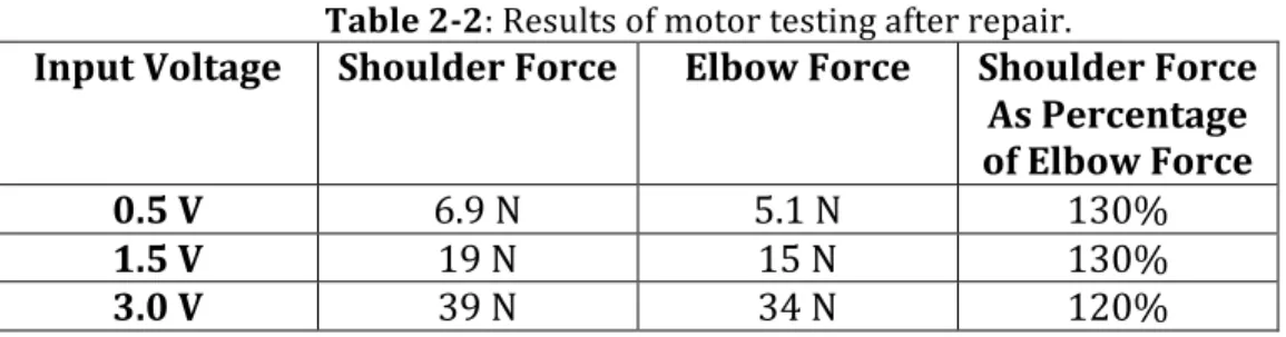
The InMotion2 robot is a clinical version of the MIT-‐Manus robot, which was developed in the 1990s to help with upper limb rehabilitation of stroke survivors. In 2015, experiments were planned to use the InMotion2 robot for studies of human force and motion control. During preparation for the experiments, however, a malfunction was discovered in the robot. A series of systematic tests were carried out to determine what part of the robot was causing the malfunction. It was determined that the magnets on one of the two motors were slipping on the rotor shaft. This slippage caused the malfunctioning motor’s torque output to range from 10% to 13% of the other motor’s output given the same input signal. The malfunctioning motor was repaired, and the robot was reassembled. Tests were carried out to verify the performance of the robot, and the torque output of the
malfunctioning motor was measured to range from 120% to 130% of the other motor’s torque output, showing that the malfunction had been fixed.
Thesis Supervisor: Neville Hogan
Acknowledgements
I would like to thank my thesis supervisor, Professor Neville Hogan, for supporting me throughout this project and always being available to help and talk through the problems encountered or questions that I had. One of the most satisfying things in life is getting to the bottom of a problem with a physical system, and I am grateful to Professor Hogan for encouraging me to continue working on this project even after we had discovered the malfunction with the robot. Through the debugging process, I learned much more about the architecture of both the robot software and hardware than I would have if there had not been a malfunction with the robot at all. Thanks also to Professor Hogan for sharing with me the history of the MIT-‐Manus and InMotion2 robots.
A big thanks goes to David Mercado, a graduate student in the Newman Lab who joined me on this project in the thick of the debugging process. David was not afraid to jump right in and start switching wires around in the hardware. Within a week of his joining the project, we had isolated the malfunction to the motor.
Thanks also to Dr. Hermano Igo Krebs, who built the InMotion2 robot that we were working with. In the final stages of the project, he helped me sort through how the slippage of the magnets explained the data that we had gathered on the robot’s behavior. He also helped me understand the organization of the hardware system.
I’d like to thank Albert Wang, a graduate student in the Biomimetic Robotics Lab, who shared with us his expertise in motors and helped us test the winding resistance.
I’d also like to thank Stan Sassower, Dilyan Marazov, and others from Interactive Motion Technologies who knew exactly what the problem with the motor was and repaired it for us.
Thanks to Julieth Ochoa, a graduate student in the Newman Lab, who introduced me to the InMotion2 robot. Thanks also to the other graduate students in the Newman Lab for asking me how the project was going and supporting me through it.
Finally, thanks to my family and friends for supporting me throughout the project. Thanks especially to my friend Beth Hadley for assisting me in taking the final data about the robot’s behavior.
Table of Contents
Abstract 3
Acknowledgements 4
Table of Contents 5
List of Figures 7
List of Tables 8
1. Introduction 9
1.1 Brief History of the MIT-‐Manus and InMotion2 Robots 9
1.2 Overview of the InMotion2 Robot Hardware and Software 10
1.2.1 Robot Arm, Computer, and Force Transducer 11
1.2.2 Actuator Packages 12
1.2.3 Amplifier Box 13
1.2.4 Software 15
1.3 Original Work Plan for Human Experiments 15
2. Discovery, Localization, and Repair of the Robot’s Malfunction 17
2.1 Catalogue of Existing Software 17
2.1.1 Circular Constraint Programs 17
2.1.2 Detection of Malfunction 18
2.2 Experiments With the Clock Game 18
2.2.1 Confirmation of Malfunction 19
2.2.2 Set of Possible Problem Areas 20
2.2.3 Directionality of Malfunction 21
2.2.4 Failure Behavior and Power Cycling 22
2.3 Encoder Testing 24
2.4 Isolation of the Shoulder System 25
2.4.1 Absence of a Measure of Output Motor Torque 25
2.4.2 Use of Force Transducer to Measure Output Torque 27
2.4.3 Incorrect Calculation of Force Direction 28
2.4.4 Experiments at Varying Amplitudes of Voltage Input 28
2.4.6 Switching of Amplifier Cabling 31
2.4.7 Switching of Motor Cabling 32
2.5 Repair and Reinstallation of the Motor 33
2.5.1 Opening of Actuator Package 33
2.5.2 Testing of the Motor Internal Resistance 34
2.5.3 Reaching Out to Interactive Motion Technologies 35
2.5.4 Recalibration of Encoders and Force Transducer 35
2.5.5 Testing of the Repaired Motors 36
3. Conclusion 38
3.1 Summary of Procedures 38
3.2 Explanation of Findings 38
3.3 Future Work 39
4. Appendices 41
Appendix A: Tips and Tricks for Working with the InMotion2 Robot 41
Appendix B: Circular Constraint Programs 47
Appendix C: Program to Measure Input and Output of Individual Motors 54
Appendix D: Plots of Input Voltage and Output Force of Individual Motors 58 Appendix E: Plots of Input Voltage and Output Force After Repair 61
5. Bibliography 64
List of Figures
Figure 1-‐1: Flow of power and information through the robot system 11
Figure 1-‐2: InMotion2 robot arm with computer monitor 11
Figure 1-‐3: Two actuator packages 12
Figure 1-‐4: Outside and inside of amplifier box 13
Figure 2-‐1: Clock game display 19
Figure 2-‐2: Top view of the InMotion2 arm with compass face 21
Figure 2-‐3: Display provided by the vex program 24
List of Tables
Table 2-‐1: Results of initial motor testing 30
Table 2-‐2: Results of motor testing after repair 36
1.
Introduction
Every roboticist has had the experience of watching a robot behave in a way
different than expected and having to figure out why. Debugging problems comes with the territory in robotics, because robots are made up of so many different parts, ranging from mechanical parts to electrical parts to software. This thesis presents a case study in troubleshooting a complex software-‐controlled electromechanical system, namely the InMotion2 robot, which is a clinical version of the MIT-‐Manus robot. The hope is that the debugging process will be of use to the wider robotics community, and that the specific problems and their solutions will be of use to future engineers and scientists working with the InMotion2 robot.
1.1 Brief History of the MIT-‐Manus and InMotion2 Robots
The first prototype of the MIT-‐Manus robot was built in the Newman Lab for Biomechanics and Human Rehabilitation in 1991 by Jain Charnnarong [1] as part of his master’s thesis. The goal was to build a robot that was backdrivable and could vary its stiffness, so that it could guide stroke victims through a series of exercises to help them regain the use of their arms. Subsequent studies throughout the 1990s showed that therapy with the robot was more effective than therapy with a human therapist, and that the effects of the therapy lasted at least three years [2]. With this success, the MIT-‐Manus robot launched the field of rehabilitation robotics, which has grown ever since.
In 1998 and 1999, a pair of master’s theses by Debo Adebiyi [3] and Craig Foster [4] dealt with the fabrication and characterization of a beta prototype version of the MIT-‐
Manus robot. The changes made in this version of the robot were mostly to the mounting base and the actuator package, in order to make the parts of the robot easier to
manufacture. Also in 1998, a company called Interactive Motion Technologies (IMT) was founded to manufacture the MIT-‐Manus robot for hospitals, rehabilitation centers, and neurorehabilitation researchers [5]. The clinical version of the MIT-‐Manus robot was renamed to the InMotion2 robot, and later, the InMotion ARM. IMT still manufactures and distributes the robots, and has since developed at least three new designs based on the MIT-‐Manus robot, with the goal of making the robot smaller and more portable.
The robot that this paper deals with is one of the very early InMotion2 robots built by IMT. It was bought by the Newman Lab around 2003 and has since been used mainly for demonstrations to visitors in the lab. Its only extensive use was for a project done by Jerome Palazzolo in 2007 [6], in which the robot measured the stiffness of the human arm by creating stochastic force perturbations and measuring the corresponding motion.
1.2 Overview of the InMotion2 Robot Hardware and Software
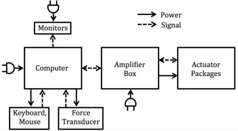
The InMotion2 robot hardware consists of an arm, a mounting table, two actuator packages, an amplifier box, and a computer with monitors, a keyboard, and a mouse. The computer contains built-‐in software that controls the movement of the robot, and it also provides a programmable platform so that the robot can produce custom movements. Figure 1-‐1 shows a block diagram describing the flow of power and information through the robot system. Each piece of the block diagram will be described in the following paragraphs.
Fig. 1-‐1: Flow of power and information through the robot system. Arrows denote
which way power or information flows, and the plug symbol denotes which pieces plug into the wall. Note that the actuator packages move the arm.
1.2.1 Robot Arm, Computer, and Force Transducer
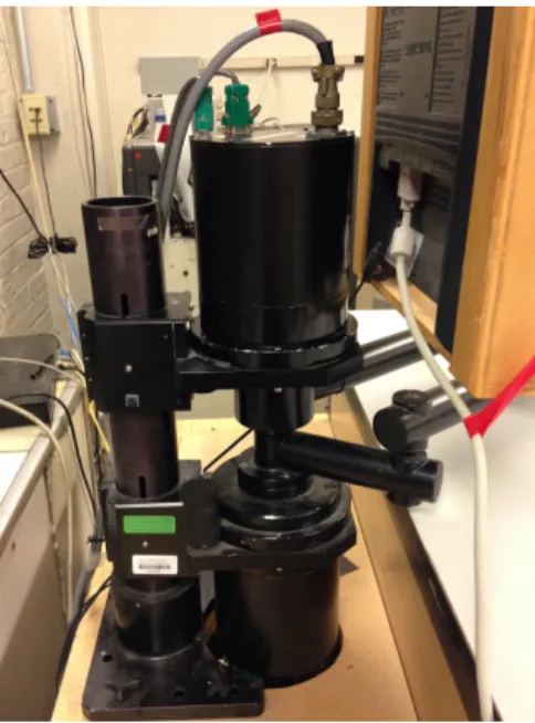
Figure 1-‐2 shows the robot arm, computer monitor, and force transducer.
Fig. 1-‐2: InMotion2 robot arm with computer monitor. The arm rests just above the
table and provides the physical interface with the user. The computer monitor is mounted above the arm to give users visual feedback. The force transducer is located between the handle and the rest of the arm in order to sense the forces that the user feels.
The robot arm is essentially a two link, two degree-‐of-‐freedom mechanism that interfaces with the user’s hand through a vertical handle at its end. The arm can move only in the plane of the table. The user sits in a chair at the table so that the arm is at a
comfortable height. A three-‐axis force transducer is mounted between the handle and the rest of the arm and measures the reaction force between the handle and the rest of the arm in the x, y, and z directions. The computer monitor is mounted above the robot so that the user of the robot can receive visual feedback on the position of the robot arm.
Programmers and users can interact with the computer through a keyboard and mouse.
1.2.2 Actuator Packages
Movement of the arm and sensing of its position are carried out by the actuator packages. The robot contains two actuator packages, one for each degree of freedom of the arm, as shown in Figure 1-‐3.
Fig. 1-‐3: Two actuator packages. The top cylinder controls the “shoulder” joint of
The upper actuator package controls the angular position of the joint of the arm closest to the actuators, also called the “shoulder.” The lower actuator package controls the position of the other joint, the “elbow.” Each actuator package contains: 1.) a custom-‐made, three-‐phase AC motor for supplying torque and angular velocity to one of the links of the arm, 2.) a virtual absolute encoder for sensing the angular position of the corresponding link, and 3.) a Hall effect sensor for sensing the position of the motor upon startup.
1.2.3 Amplifier Box
The amplifier box connects the computer to the actuator packages. It takes in power from an outlet and voltage signals from the computer and converts those two inputs into an output signal that can be sent to the motors to move the robot arm. Additionally, the
amplifier box converts data from the encoders into a form that can be sent back to the computer. The amplifier box also contains many safety features to ensure that the robot will not injure anyone. Figure 1-‐4 shows the outside and inside of the amplifier box.
Fig. 1-‐4: Outside and inside of amplifier box.
On the outside of the box, there is a power switch to turn on and off the robot hardware that is contained within the amplifier box and the actuator package. Note that the computer has its own power switch, which also powers the force transducer. There are also buttons to start and stop sending voltages to the motors. In addition, there is an
emergency stop button, which short-‐circuits the motor terminals to apply dynamic braking on the motors, and a reset button to undo the short circuits and allow current to flow to the motors.
Inside the amplifier box, there are: 1.) the power switch, 2.) a ground fault current interrupter, which will cut the power to the machine if any part of it shorts to ground, 3.) circuit breakers to ensure that currents do not rise to unsafe levels, 4.) two isolation transformers to keep the power sent to each of the two amplifier-‐motor systems isolated from the external power, 5.) two noise filters to even out the power signal to be sent to the amplifiers, 6.) two amplifiers, which regulate and send current directly to the motors; the amplifiers also read from the Hall effect sensors and encoders in the actuator boxes to determine the position of each motor, 7.) dynamic braking relays, which stop the motors when the emergency stop button is pressed, and let the motors move when the reset button is pressed, 8.) relays to introduce time delay into the start up of the robot, so that transients do not cause problems with the circuit, 9.) a programmable logic controller, which responds to the start and stop buttons and ensures that everything is functioning properly before the motors receive voltages, 10.) power supplies to provide 12 V and 24 V to the devices such as the relays that need a lower level of voltage than comes out of the wall outlet, and 11.) the encoder I/O modules, which process the encoder data to be sent back to the computer.
1.2.4 Software
The robot software runs in the environment of a Linux operating system. Thus, the various processes that occur on the computer are managed by a program called the Linux kernel. The robot software makes use of a plugin called “Real-‐Time Linux,” or “RTLinux,” which takes control of the Linux kernel and manages the interaction between the hardware and software in real time [7]. The background code that manages operation of the robot, e.g. low-‐level communication with the sensors and actuators, is written in C, so that it can be loaded into the kernel. User mode programs, written in a language called Tcl/Tk,
interface with the background code to control the movement of the robot, allowing the user to send more high-‐level commands to the robot, e.g. movement of the handle to a specific location in a specified amount of time. Typical programmers of the robot will need to understand and modify a few files from the background C code, but will mostly be creating new user mode programs in Tcl/Tk.
1.3 Original Work Plan for Human Experiments
The original research goal was to use the InMotion2 robot to conduct tests on human subjects to gain a deeper understanding of how humans control the force and motion of our arms. This work would be part of a pilot study for a project to be completed between February 2016 and January 2021. The idea was to program the robot to impose various constraints on the motion of the handle, e.g. a curved kinematic constraint to simulate pushing a drill against a flat surface, and have human subjects push against the robot at a percentage of their maximum possible force. During the testing, the robot would exert
various perturbations on the robot handle, thus allowing measurement of the stiffness of the subject’s arm.
The planned sequence of work was to first, catalogue any software that had been written by previous Newman Lab members that could be reused, and then write any additional software necessary. After the software had been written, a plan would be made for human subject testing, and the tests would be carried out and written
up. Unfortunately, due to a malfunction of the robot that had gone unnoticed for an unknown period of time before this project began, the original plan was derailed after the cataloguing of the existing software. Instead, the time dedicated to this project was spent getting to the bottom of the malfunction. The rest of this paper describes the process by which the malfunction was discovered, quantified, and fixed.
2.
Discovery, Localization, and Repair of the Robot’s Malfunction
2.1 Catalogue of Existing Software
2.1.1 Circular Constraint Programs
The first couple weeks of the project were spent getting familiar with the robot software written in C and Tcl/Tk and the code that had already been written by previous lab members that could be used to create kinematic constraints relevant to this
project. See Appendix A for a compendium of tips and tricks based on information learned about the robot hardware and software throughout the project. As far as relevant code, there was one relevant user-‐mode program, i.e. a program written in Tcl/Tk, with its
corresponding entries into the data-‐logging and robot-‐moving programs, which are written in C. This program was written by postdoc Jooeun Ahn and undergraduate researcher Joy Park during the summer of 2014, and it is included in Appendix B, along with the relevant parts of the data-‐logging and robot-‐moving programs. The program constrains the robot arm to move in a circle of user-‐input radius. The robot arm moves as if it is constrained into the circular shape by an elastic band, with a user-‐input stiffness that determines the force that the user feels as a function of the distance they have moved the handle away from the closest point on the circle. The robot arm also moves with a user-‐input damping, which exerts an opposing force proportional to the handle’s velocity and helps keep the handle position stable. Changing which robot-‐moving program is used for the program can make the robot arm constrain motion in the same circle while also exerting stochastic force
perturbations on the handle and recording its corresponding motion in order to calculate the stiffness of the user’s hand.
2.1.2 Detection of Malfunction
Upon running Jooeun’s and Joy’s circular constraint program, it was difficult at first to tell if the program was working, because the units of the user-‐input radius, stiffness, and damping were unknown, so it wasn’t clear what the robot was being commanded to do given a set of inputs. After looking further into the code, it was determined that the radius was in meters, the stiffness in N/m, and the damping in N/(m/s). Using this information, the program was run again with reasonable inputs, and it became clear that the robot was not correctly constraining the motion of its handle to a circle. It would allow the handle to be moved out of the desired circle at certain points, and then it would wrench the handle forcefully back into the circle at other points. This behavior was definitely not suitable for the originally planned experiments, as they relied on an almost perfect circular constraint, in which users could push forcefully against a simulated “wall” and expect the robot to push back with equal force. At this point in time, it was not clear whether this malfunction was a problem with this particular user-‐mode program or with another part of the robot, so an older, more well established program was run to see if the malfunction was still present.
2.2 Experiments With the Clock Game
2.2.1 Confirmation of Malfunction
One of the very first programs implemented on the MIT-‐Manus robot for stroke rehabilitation was called the clock game. Figure 2-‐1 shows a picture of the computer monitor during this game.
Fig. 2-‐1: Clock game display.
In the clock game, the position of the handle of the robot is represented on the computer monitor in real time by the motion of a yellow dot. In addition, the center of the robot’s workspace is represented in the center of the screen by a black dot, and eight different black dots are equally spaced around the center dot, forming a circle that looks similar to a clock face. When each dot blinks red and yellow, the user is expected to move the robot handle until the handle’s dot touches the blinking dot. Then, another dot will start blinking. The dots blink sequentially, and thus the user gets to practice movement in each of eight directions. Additionally, the robot is programmed to allow the user two seconds to move the handle before assisting the motion to the next dot.
This game was known to have been working at some point on this machine, so it was used to test the robot’s function to determine whether the malfunction occurred during this game as well as during the circular constraint program.
Upon a cursory observation of the robot during this task, it appeared to work as desired, which explains how the malfunction could have gone unnoticed for a period of time. If, for example, the robot handle were left on its own, without a person touching it, it would wait two seconds at each location, and then move to the next location, as it
should. Also, if the person moved the handle perfectly, taking less than two seconds to move directly to the next point, the robot exerted no resistance, as it should. However, as soon as the person started to “fight” with the robot, moving the handle in a way opposite to the way that it was programmed to go, the robot started to malfunction, first by becoming weak in its ability to move in certain directions, and then by moving in the wrong direction. Thus, the malfunction was not simply a coding error within the circular constraint
program.
2.2.2 Set of Possible Problem Areas
At this point in the analysis, the malfunction could have been caused by many different things. It could have been a problem with: 1.) both the circular constraint and clock game user mode programs, although it was unlikely that both user mode programs had been accidentally modified to create this problem, 2.) the background code shared by both the circular constraint and clock game user mode programs; for example, one of the calibration values for one of the sensors or actuators might have been accidentally changed in the code, 3.) any of the connecting wires between the many pieces of hardware that
made up the robot, 4.) any of the pieces of hardware that made up the robot. It was necessary to do some more observation of the malfunction to eliminate some of these possible problem areas.
2.2.3 Directionality of Malfunction
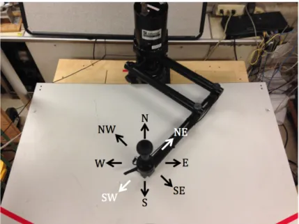
At the beginning of the clock game, the robot is programmed to hold its position in the center of the workspace, resisting any changes in position until the user presses the spacebar to start the program. During this time, if the handle is pushed in any direction, the robot should exert a restoring force increasing with the distance from the handle to the center of the workspace. This worked as expected when the handle was pushed towards the N, NW, W, S, SE, and E directions. However, when the handle was pushed towards the NE or the SW, the robot resisted the handle’s motion for a very short amount of time, and then gave way to the applied force. Figure 2-‐2 shows these failure directions visually.
Fig. 2-‐2: Top view of the InMotion2 arm with compass face. The compass face
represents the eight main directions of motion of the handle. When the handle was moved towards the NE or SW, the robot failed to constrain the motion of the handle, but when moved towards any other direction, it succeeded in constraining motion.
Note that the two failure directions are the directions actuated solely by the motor at the shoulder. This observation greatly diminished the set of possible problem areas, as the range of possible hardware problems decreased to only those connections and modules in the chain leading to the shoulder, not those leading to the elbow or those shared by both the shoulder and the elbow. Also, the range of possible software problems decreased to only those that dealt with calibration of and interfacing to those pieces of hardware.
2.2.4 Failure Behavior and Power Cycling
A few more observations shed even more light on the possible contributors to the malfunction. No matter whether the robot was running the circular constraint program, the clock game in its pre-‐start configuration, which constrained the handle to the center of the workspace, or the clock game in its post-‐start configuration, which allowed the handle to move around the clock, the only way to make the robot “fail” seemed to be pulling or pushing the handle too far in the direction controlled by the shoulder actuators and sensors.
After the failure of the robot, its reaction force continued to be weaker than expected in response to forcing of the handle along the direction controlled by the shoulder, while still seeming as strong as before the failure in the elbow-‐controlled direction.
Also, notably, after failure of the robot, when the clock game was run and the robot was allowed to move unconstrained without a person holding the handle, the robot was no longer able to follow the desired trajectory. This metric of whether the robot could move
itself properly around the clock game without a person holding the handle allowed a clear distinction between when the robot was in failure mode and when it had not yet failed. In an effort to determine whether the malfunction was with the hardware or the software, the robot was put into failure mode, and various procedures were tried to see if they brought the robot out of failure mode. First, the clock game program was closed and reopened, to see if the reason for the failure mode was a value stored within the program itself. This did not succeed in restoring the robot. Next, the login session on the computer was restarted, to no avail. Finally, the computer was powered off and powered on again to see if the problem was in any of the values stored in the software. None of these
procedures brought the robot out of failure mode. The only way that was found to restore the robot to its pre-‐failure state was to flip the power switch on the amplifier box to off, which cut off power to all of the hardware inside the amplifier box and the actuator package, and then to flip that switch back on. After power cycling the amplifier box, the robot was able to successfully move its handle accurately around the clock face without a person holding it, until the handle was once again pushed too far in the direction controlled by the shoulder.
At this point, all signs were pointing to a problem with the robot’s hardware, not its software, and it was known that the problem was somewhere in the chain leading from the computer to the shoulder actuator package. Now, the possible problem areas were the shoulder encoder, shoulder motor, shoulder amplifier, connections between these modules, and possibly other pieces of hardware inside the amplifier box that eventually led to the shoulder but not the elbow. As a side note, the force transducers were not used in the clock game or the circular constraint program, so they were not the source of the failure.
2.3 Encoder Testing
Included with the IMT2 Software is a program called “vex,” which stands for “vectors.” Figure 2-‐3 shows the vex display on the computer monitor.
Fig. 2-‐3: Display provided by the vex program.
This program displays on the screen a dot showing the location of the robot handle as well as a series of vectors showing the velocity of the handle as calculated from the encoder readings. Additionally, the three-‐axis reading of the force transducer is displayed, and the force commands in x and y sent to the motors are displayed as vectors on the screen.
Using this program’s display, it was easy to tell that both shoulder and elbow encoders were working correctly both before and after the robot had failed, because the dot showing the position of the robot handle moved in real time in conjunction with the motion of the handle in the real world. Also, the vectors showing the velocity of the robot handle moved in real time at least in the right directions, with the right relative
magnitudes. Thus, the possibility of the problem area being the shoulder encoder was eliminated.
2.4 Isolation of the Shoulder System
At this point, the focus was directed towards doing a system ID of the shoulder and elbow amplifier-‐motor-‐connector-‐other relevant hardware systems independently from one another. A new program was needed that would send inputs and record outputs separately through the shoulder and elbow systems. None of the programs described thus far were capable of this, as they had all depended on x-‐y position, which is a function of both shoulder and elbow angle, not one of them alone. The hope was to send, for example, a sinusoid in voltage through the shoulder amplifier and cabling and other hardware to the shoulder motor, and then measure the output torque produced by the motor. It would be interesting to compare the inputs and outputs at various frequencies and amplitudes of sine waves in order to quantify the voltage, current, or torque at which the shoulder system fails. Aside from learning how to print and log data about the robot in real time, the
hardest part of this endeavor was finding a way to measure the output torque of the motor.
2.4.1 Absence of a Measure of Output Motor Torque
There was very little documentation available on the InMotion2 robot, so it was unknown whether its actuator package contained either a reaction torque sensor that directly measured the output torque of the motor or a current sensor that measured the current sent to the motor, from which the output torque could be calculated by multiplying by the motor constant. Within the software, there are a variety of variables calculated or measured during the operation of the robot that can be logged into a data file for later use or printed in real time to the terminal window. Two of these variables are called “s_torque” and “e_torque” in Tcl/Tk and stand for “shoulder torque” and “elbow torque.”
At first, it was unclear whether these variables referred to the output torque of each motor measured through a torque or current sensor, or even perhaps calculated from the output of the force transducer, or whether they referred to some other torque. However, upon taking a closer look at the file pl_sensact.c, which is part of the IMT2 Software in C and shows the calculations to determine several of the variables available for logging and
printing, it was determined that first, the desired motor forces in x and y are calculated based on the robot’s control scheme. Then, these values are combined with knowledge about the geometry of the robot to calculate the desired torques at each motor. Finally, these desired torques are used to calculate the voltage commands that get sent from the computer through the entire amplifier-‐motor-‐connector-‐other hardware chain. Thus, it was determined that the variables “s_torque” and “e_torque” are not measures of the output torque at each motor, but of the desired torque at each motor.
This observation was also confirmed experimentally by watching the data displayed by the vex program during the running of its “star” program. Another part of the vex
program that was not described above is that it is capable of moving the handle similarly to how the handle moves in the clock game, moving around to eight points equally spaced around a circle. When this star program is run, vectors are displayed on the screen
showing the commanded motor forces in x and y, and values are shown for the commanded motor voltages to the elbow and shoulder. The observation was that the motor force
vectors appeared the same way on the screen no matter whether the brakes were off and the robot arm was free to move, or whether the brakes were on and the motor did not actually move. This showed that the motor forces, torques, and voltages were all commands, and not measurements of actual behavior. The InMotion2 robot does not
contain a motor output torque sensor. Interestingly, in Charnnarong’s thesis, it says that the first MIT-‐Manus prototype contained a torque sensor, but in Adebiyi’s thesis, it says that, for the second MIT-‐Manus prototype, the designers did not put in a torque sensor, but only left space for one. The subsequent iterations of the robot did not contain a torque sensor either.
2.4.2 Use of Force Transducer to Measure Output Torque
Once it was determined that neither a torque sensor nor a current sensor was present in the robot, the only other options for measurement of the output of the robot were to gather data from the encoders or the force transducer. Given an input sinusoid in voltage sent to one of the motors, the handle could be allowed to move freely and its position or velocity could be measured, or the handle could be restrained as much as possible and its force could be measured. The second method was implemented, as it more closely resembled the failure modes that had already been seen, in which the robot seemed to fail when too much force was applied to the handle that opposed the motion of the motor. Also, holding the handle stationary seemed safer than allowing it to move freely, as it did not require the handle to move at possibly dangerous speeds.
Thus, a program was written to command a sinusoid in voltage to one or both motors while logging both the input voltages and the forces at the force transducer. Which motor would receive the voltages, as well as the frequency and amplitude of the signal, was chosen by the user upon starting the program. The program is presented in Appendix C.
2.4.3 Incorrect Calculation of Force Direction
During the writing of the program in Appendix C, it was determined that the software was not correctly calculating the direction of the force measured by the force transducer. This was made obvious during use of the vex program. The vex program displays on the screen the forces measured by the force transducer in x and y as referenced from the device itself, and it also displays the forces measured by the force transducer in x and y relative to the table.
When the handle was pushed in various directions while holding the arm steady, the vex program displayed the device forces in the correct direction and with the correct
relative magnitude. However, the world forces were not shown in the correct
direction. They appeared to be always off from what was expected by approximately 135 degrees.
At this point, it was unknown how to fix this issue, and since it did not affect the magnitude of the measured world forces, fixing it was not a priority. Instead, the focus was on conducting experiments using the newly written input-‐output recording code.
2.4.4 Experiments at Varying Amplitudes of Voltage Input
Several experiments were carried out to quantify at what amplitude of voltage the shoulder system failed. In order to protect the hardware, the IMT2 software limits the magnitude of the voltage command sent to the amplifiers to 5 volts, so only amplitudes lower than 5 V were tested. Qualitative observations are presented first, and then quantitative results.
First, a sinusoid in voltage of frequency 2 Hz and amplitude 0.5 volts was sent to the shoulder motor. The handle was held as close as possible to the center of the workspace, and the sinusoid in voltage was felt as a sinusoid in force along the NE-‐SW line.
Next, a sinusoid in voltage of the same frequency but amplitude 3 volts was sent to the shoulder motor. In this case, however, the forces did not go up by a factor of 6 from the previous experiment as would have been expected. Instead, they felt lower than in the previous experiment, implying that the robot had failed at this voltage.
Without power cycling the amplifier box, a sinusoid in voltage of the same frequency but amplitude 1.5 volts was sent to the shoulder motor. In this case, the forces felt at the handle seemed to be even lower than in the previous experiment. Finally, the amplitude was decreased back down to 0.5 volts, and the output force was felt to be almost non-‐ existent.
As a second set of experiments, sinusoids in voltage at the same frequency were sent to the elbow motor first at an amplitude of 0.5 volts, and then at an amplitude of 3
volts. This time, the forces, which were felt along the NW-‐SE line, scaled as expected, with a great deal more force felt at the amplitude of 3 volts than at the amplitude of 0.5 volts.
These experiments determined that the shoulder system failed at a voltage
somewhere between 0.5 V and 3 V, and that the elbow system did not fail at any voltage at or below 3 V.
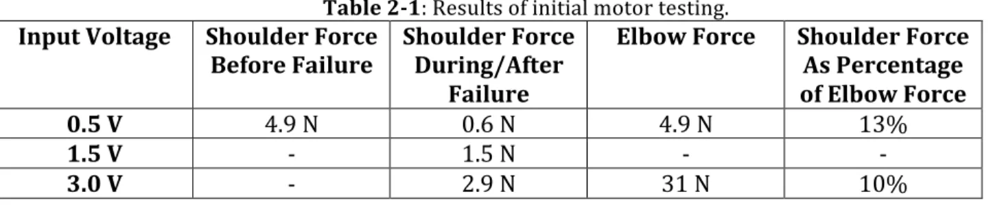
Table 2-‐1 shows the calculated values of the force magnitudes based on the x and y force data from the force transducer, and their corresponding input voltages.
Table 2-‐1: Results of initial motor testing.
Input Voltage Shoulder Force
Before Failure Shoulder Force During/After Failure
Elbow Force Shoulder Force As Percentage of Elbow Force 0.5 V 4.9 N 0.6 N 4.9 N 13%
1.5 V -‐ 1.5 N -‐ -‐
3.0 V -‐ 2.9 N 31 N 10%
As shown in the table, before the failure of the shoulder motor, its force magnitude was the same as that of the elbow motor for the same input voltage magnitude. However, after its failure, the shoulder force magnitude decreased to between 10% and 13% of the corresponding elbow force magnitude. This agrees with the qualitative observations. Complete graphs for each trial of this experiment are presented in Appendix D.
2.4.5 Amplifier FoldBack
During one of the first times that the robot failed, the amplifier box was opened, and it was noticed that the servo amplifier that controlled the current going into the shoulder motor read “F,” while the other amplifier read “3.” It was later observed that every time the robot failed, the amplifier leading to the shoulder motor read “3” as usual for about 30 seconds, and then switched to “F.” It was unknown what this meant until the manual for the servo amplifier was consulted. The manual explained that, during normal operation, the amplifier displays a number between 1 and 8 to describe the mode of operation [8]. A display of “3” means that the amplifier is configured as a torque controller and is controlled via an analog voltage input signal. In this mode, the current sent to the motor is
Additionally, a display of “F” means that the amplifier has entered FoldBack mode. The FoldBack detection system protects both the amplifier electronics and the motor from undergoing too much current. This system monitors the current sent to the motor, and if that current exceeds the continuous current rating of the amplifier/motor combination, decreases the system’s current to that level. The amount of time for which the current can be above the continuous current rating before the amplifier goes into FoldBack mode is 0.5 seconds when the current coming out the amplifier is at its maximum possible value, and the allowed time increases as the value of the output current drops towards the continuous current rating.
All of this information pointed to the idea that either the shoulder motor and its connecting wires were drawing too much current from the shoulder amplifier, or the shoulder amplifier was miscalibrated or broken, or a problem with some hardware in the shoulder chain before the amplifier was causing the amplifier to go into FoldBack mode. In order to determine which of these was the case, the idea of switching the cabling between the shoulder and elbow systems was explored.
2.4.6 Switching of Amplifier Cabling
First, in order to determine whether the shoulder amplifier was malfunctioning, all of the input and output wires going to and from the shoulder amplifier were switched with all of the input and output wires going to and from the elbow amplifier. Since it was known that the elbow amplifier worked correctly, the behavior of the robot with these connections switched would point to whether the problem was with the amplifier or with another part of the shoulder system, or both. Observation of the robot in this configuration showed that,