Seeing the Corona with the Solar Probe Plus Mission: The Wide-Field
Imager For Solar Probe+ (WISPR)
Angelos Vourlidas*
a, Russell A. Howard
a, Simon P. Plunkett
a, Clarence M. Korendyke
a, Michael T.
Carter
a, Arnaud R. Thernisien
b, Damien H. Chua
a, Dennis G. Socker
a, Mark G. Linton
a, Paulett C.
Liewer
c, Jeffrey R. Hall
c, Jeff S. Morrill
a, Eric M. DeJong
c, Zoran Mikic
d, Pierre L.P.M. Rochus
e,
Volker Bothmer
f, Jens Rodman
f, Philippe Lamy
ga
Space Science Division, Naval Research Laboratory, 4555 Overlook Ave, S.W., Washington, DC,
USA 20375;
bGeorge Mason University, 4400 University Dr, Fairfax, VA USA;
cJet Propulsion
Laboratory, USA;
dPredictive Sciences Incorporated, San Diego, CA, USA;
eCentre Spatiale de
Liege, Univ. de Liège, Belgium;
fGeorg-August-Univ. Göttingen, Germany;
gLaboratoire
d'Astrophysique de Marseille, France
ABSTRACT
The Solar Probe Plus (SPP) mission scheduled for launch in 2018, will orbit between the Sun and Venus with diminishing perihelia reaching as close as 7 million km (9.86 solar radii) from Sun center. In addition to a suite of in-situ probes for the magnetic field, plasma, and energetic particles, SPP will be equipped with an imager. The Wide-field Imager for the Solar PRobe+ (WISPR), with a 95º radial by 58º transverse field of view, will image the fine-scale coronal structure of the corona, derive the 3D structure of the large-scale corona, and determine whether a dust-free zone exists near the Sun. Given the tight mass constrains of the mission, WISPR incorporates an efficient design of two wide-field telescopes and their associated focal plane arrays based on novel large-format (2kx2k) APS CMOS detectors into the smallest heliospheric imaging package to date. The flexible control electronics allow WISPR to collect individual images at cadences up to 1 second at perihelion or sum several of them to increase the signal-to-noise during the outbound part of the orbit. The use of two telescopes minimizes the risk of dust damage which may be considerable close to the Sun. The dependency of the Thomson scattering emission of the corona on the imaging geometry dictates that WISPR will be very sensitive to the emission from plasma close to the spacecraft in contrast to the situation for imaging from Earth orbit. WISPR will be the first ‘local’ imager providing a crucial link between the large scale corona and the in-situ measurements.
Keywords: Solar Probe Plus, Heliospheric Imager, Solar Corona, Solar Wind, Imaging, Thomson Scattering
1. INTRODUCTION
Heliophysics seeks to understand how the structure and dynamics of the solar system are controlled by the outflow of plasma and magnetic field from the Sun, known as the solar wind. The answers lie in the solar corona, the conduit of energy and activity that powers the solar wind and heliosphere. Coronal Mass Ejections (CMEs) and flares, the most explosive events in our solar system, trace their origins at the lower levels of the corona, a few thousand kilometers above the solar surface. The opening and closing of the coronal magnetic field affect the speed, and other properties of the solar wind around the Earth. The interplay between CMEs and background wind can wreak havoc at the terrestrial magnetosphere and result in serious problems for human technological systems all the way from satellite operations to transpolar flights to electricity grids on the ground. However, several, fundamental questions remain unanswered: what
heats the corona (or equivalently, how is the solar wind accelerated)? Where does the wind turn supersonic? How are energetic particles accelerated and escape in the interplanetary medium? What is the fine scale structure of the magnetic field in the outer corona, especially at the boundaries between open and close field lines?
Little is known about the physical conditions of the inner corona where these phenomena originate. The corona has been studied only remotely so far and major physical parameters, such as the strength of the magnetic field, the small-scale density structure and the plasma velocity distributions there, are unknown. The obvious solution is to directly measure these physical properties by sending a probe into the inner corona. Only then, we will be able to make fundamental
progress towards understanding the solar corona. This is exactly what NASA is planning to do with the Solar Probe Plus mission.
1.1 The Solar Probe Plus (SPP) Mission
SPP is a pioneering robotic space mission to visit and probe the atmosphere of the Sun, funded by the NASA Heliophysics Science Division and managed by the Applied Physics Laboratory (APL) at the Johns Hopkins University in Laurel, MD. The SPP spacecraft (s/c) will be the first manmade object to enter and orbit the solar corona at 9.86 Rs from Sun center after using a series of Venus gravity assist maneuvers to reduce its perihelion. The SPP s/c is scheduled for launch in the summer of 2018 with the first perihelion passage (at 35 Rs) only three months later. The sever year mission will study the coronal evolution over a significant portion of the solar cycle with direct observations of heliospheric plasmas unobtainable in any other way. The SPP s/c will spend a total of 961 hours inside 20 Rs, 434 hours inside 15 Rs, and 30 hours inside 10 Rs during the 7-year prime mission. Because of power, telemetry and operational constraints, observations will be taken only below 0.25 AU which results in 10 observing days out of the 88-day orbit (Figure 1). In other words, SPP is an encounter mission and not the usual synoptic heliophysics mission. The goal of the SPP mission is to understand the origins of the solar wind and the structure and dynamics of the coronal magnetic field. The s/c carries a complement of three in-situ experiments to directly measure the plasma and magnetic field properties (FIELDS and SWEAP) and the energetic particle populations (ISIS) in the solar corona. It also carries the Wide-field Imager for Solar PRobe (WISPR), a heliospheric imager to provide the large-scale context of the structures encountered by the s/c.
WISPR, developed by the Solar Physics Branch at the Naval Research Laboratory (NRL), is the only imaging instrument on the SPP payload and has two primary responsibilities: (1) provide the crucial link between the in-situ observations from SPP and the large scale structure of the corona that is needed to address SPP science, and (2) enhance the scientific return of the mission with trailblazing observations of the fine scale structure of the solar corona and of the nature of the interplanetary dust. Given the strongly varying heliocentric distance, the instrument requires a large field of view (FOV), high contrast imaging, and high spatial resolution. Essentially, WISPR will be imaging the coronal structure from the
inside, because of the close proximity of the imager to the target structures. To accomplish this, WISPR will have a field
of view larger than the combined SECCHI/HI1-2[1] imagers with twice the imaging resolution, at closest approach, of the
SECCHI/COR2 coronagraph. These properties will allow WISPR to address the SPP level-1 science objectives: 1. Determine the structure and dynamics of the magnetic fields at the sources of the fast and slow wind 2. Trace the flow of energy that heats the solar corona and accelerates the solar wind.
3. Explore mechanisms that accelerate and transport energetic particles.
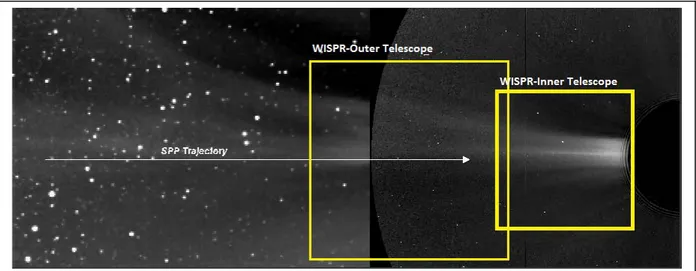
Figure 1 The SPP trajectory as viewed from a distance of 1 AU is projected onto a combined SECCHI/HI and COR2 image. The yellow boxes represent the WISPR FOVs at closest perihelia (9.86 Rs). The spatial resolution of WISPR will be about 4x higher than this image (36 arcs/pix).
Because of the unique orbit and imaging capabilities of the instrument, the WISPR investigation has defined two additional science question goals:
a. What is the dust environment in the inner heliosphere?
b. What is the nature of dust-plasma interactions and how does dust modify the spacecraft environment close to the Sun?
WISPR is being developed with significant heritage from the SECCHI heliospheric imagers aboard the STEREO mission and from the SoloHI imager under development for ESA’s Solar Orbiter mission [2] scheduled for launch in
2017. In fact, SoloHI, described elsewhere in this volume [3], provides many of the design elements and subsystems for
adaptation into the WISPR design.
A final note about SPP concerns the environment. The s/c will enter an environment about which little is known. The instruments will be protected by the intense radiation (>400x than at Earth) by a carbon-carbon multilayer heat shield but the properties of the energetic particle and dust populations in the vicinity of the Sun can only be modeled or simulated. Dust damage is of particular concern to the various s/c subsystems and the APL s/c team has undertaken a vigorous modeling, simulation and test program to mitigate the dust risk to the best extent possible. Dust damage mitigation is also one of WISPR’s main activities during the design phase as we will see in 2.4.
2. WISPR INSTRUMENT DESIGN
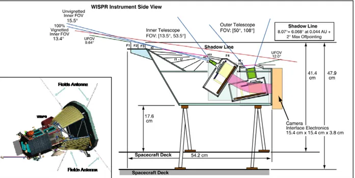
The WISPR instrument concept is in effect a miniaturization of the SECCHI/HI concept with adaptations from the SoloHI design. It is a two-telescope system, similar SECCHI/HI, with an inner telescope extending from 13.5 º to 53º and an outer telescope extending from 50º to 108º (Figure 2, right). The two-telescope implementation is driven by the need to baffle the telescope against the intrusion of two of the FIELDS antennas (Figure 2, left) into the WISPR unobstructed FOV. The instrument uses the heat shield as the first occulter and hence the alignment between the heat shield and the first occulter baffle, F1 is a critical element for the successful control of the stray light (see Section 2.2). The inner FOV cutoff is set at an elongation of 13.5º from sun center, corresponding to a heliocentric distance of 2.3 Rs at 9.86 Rs perihelion. The cutoff is dictated by two requirements: (1) to remain within the heat shield umbra (8º, including a 2º maximum s/c offpoint), and (2) to accommodate the instrument on the s/c bus at a reasonable height and with reasonable mass. The overall instrument characteristics are shown in Table 1.
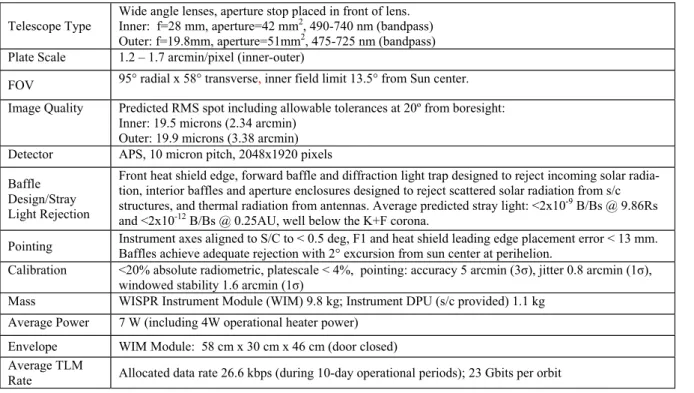
Table 1 WISPR Instrument Characteristics
Telescope Type Wide angle lenses, aperture stop placed in front of lens. Inner: f=28 mm, aperture=42 mm2, 490-740 nm (bandpass) Outer: f=19.8mm, aperture=51mm2, 475-725 nm (bandpass) Plate Scale 1.2 – 1.7 arcmin/pixel (inner-outer)
FOV 95° radial x 58° transverse, inner field limit 13.5° from Sun center.
Image Quality Predicted RMS spot including allowable tolerances at 20º from boresight: Inner: 19.5 microns (2.34 arcmin)
Outer: 19.9 microns (3.38 arcmin)
Detector APS, 10 micron pitch, 2048x1920 pixels
Baffle Design/Stray Light Rejection
Front heat shield edge, forward baffle and diffraction light trap designed to reject incoming solar radia-tion, interior baffles and aperture enclosures designed to reject scattered solar radiation from s/c structures, and thermal radiation from antennas. Average predicted stray light: <2x10⁻⁹ B/Bs @ 9.86Rs and <2x10-12 B/Bs @ 0.25AU, well below the K+F corona.
Pointing Instrument axes aligned to S/C to < 0.5 deg,Baffles achieve adequate rejection with 2° excursion from sun center at perihelion.F1 and heat shield leading edge placement error < 13 mm. Calibration <20% absolute radiometric, platescale < 4%, pointing: accuracy 5 arcmin (3σ), jitter 0.8 arcmin (1σ),
windowed stability 1.6 arcmin (1σ)
Mass WISPR Instrument Module (WIM) 9.8 kg; Instrument DPU (s/c provided) 1.1 kg
Average Power 7 W (including 4W operational heater power)
Envelope WIM Module: 58 cm x 30 cm x 46 cm (door closed)
Average TLM
The instrument concept and s/c accommodation are shown in Figure 2. A set of forward occulters (F1-F3) are located on a ledge to reduce the diffraction from the heat shield. An internal baffle assembly I1-I7 reduces this stray light component further as well as stray light diffracted from the radio antennas and other s/c structures. A set of other baffles are located at the apertures of the two telescopes to prevent any further reflections from reaching the detectors. Because of the orbit profile, the WISPR stray light rejection requirements vary as a function of elongation angle and heliocentric distance by about an order of magnitude. The most stringent requirement is 1.8x10⁻¹² Mean Solar Brightness (MSB) at
the outer edge of the FOV (90º elongation) at the largest distance from the Sun (0.25 AU). The sophisticated baffle design allows WISPR to meet this requirement and allows for high signal-to-noise (SNR) imaging ranging from 20 at the inner FOV at closest perihelion to 5 at the largest distance and FOV angles. The detectors are 2048x1920 format Active Pixel Sensor (APS) CMOS devices developed for the SoloHI program[3,4]. APS devices are much less susceptible
to radiation damage than the more common CCD devices and are therefore the best option for this mission. They also come with significant savings in terms of power and mass. These devices are described in more detail in an accompanying paper[4]. The devices are cooled to -60ºC via a passive radiator. A one-shot door is used to protect the
baffles and optics from contamination during ground operations, launch, and early flight operations.
2.1 Optical Design
The WISPR optics comprises two lens assemblies with the parameters given in Table 2 and shown in Figure 3. Both designs are based on the SECCHI/HI optics adjusted to the F# required for the WISPR application. The resolution is optimized for the FOV center, 33.5º and 79º, for the inner and outer telescope, respectively. Glasses such as LAK9G15, SF4, and SF6 were assumed for this design but the adoption of BK7 for the first lenses is being considered because it may be more resistant to dust impacts (see section 2.4). As can be seen from Table 2, the current optical design is excellent. It provides both fast lenses (low F#) and high spatial resolution (~2 pixels) for the inner and outer telescopes, respectively. This means that WISPR is potentially capable of capturing images at spatial resolutions of <2 arcmin (2200 km or ~ 3arcsec from 1AU) which are comparable to eclipse imaging from Earth. This is truly remarkable for a wide-field coronal telescope and the capability will be exploited as mission and solar condition allow. However, the current observing plan is to obtain images with 2x2 binning, as is done for SECCHI/HI, to increase the SNR and reduce the telemetry load. Higher image binning (4x4) will be required at large heliocentric distances to maintain an SNR of 5 at the outer edge of the FOV.
Table 2 WISPR Optical Design
FOV Spectral
Range (nm)
Entrance
Pupil (mm) F# # of lenses RMS Spot Size (μm)
Inner
Telescope 40º x 40º 490-740 7.31 3.83 5-element 19
Outer
Telescope 58º x 58º 475-725 8.08 4.04 6-element 20
2.2 Stray Light Control
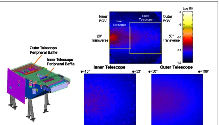
The control of stray light due to s/c accommodations has been the major focus of the WISPR team during the preliminary design phase of the project. The AO strawman payload outlined a very optimistic imager concept with a single wide-filed lens and an unobstructed 180º FOV because it did not take into account the accommodations of the radio antennas in the forward section of the s/c and into direct sunlight. As a result, two of these antennas impinged either directly into the WISPR FOV or extended into the unobstructed FOV allowing diffracted sunlight to enter the aperture at unacceptable levels. In addition, the tips of the antennas will get so hot (~1800C) that they will radiate into the visible creating another (and novel) source of stray light. The only solution for allowing the instrument to operate was to baffle directly those two sources of stray light. In order to achieve this without sacrificing most of its FOV, the WISPR single lens was split into two separate imaging assemblies as discussed above.
This change allowed the design of peripheral baffles that capture the diffracted and radiated light from the antennas and reduce the stray light to acceptable levels as shown in Figure 4. This is a preliminary result, however. The optimization of the peripheral baffle system is still under way in an effort to reduce the stray light further within the outer telescope FOV. The stray light modeling is performed via Monte-Carlo techniques with the FRED Optical Engineering software using a CAD model of the instrument and FIELDS antennas. This approach allows not only the modeling of the antenna diffracted and radiated light but also the testing of various coatings for the baffle surface and even the modeling of the effects of dust impacts during the mission as we see in section 2.4. These new stray light modeling methods, driven by the need to accommodate occulting-like imagers in crowed s/c environments, far exceed the corresponding modeling efforts in past coronagraphs and imagers where tight controls of structure intrusions in the unobstructed FOVs were possible. They demonstrate that visible light imagers can be accommodated and operate safely even when structures intrude into their direct FOVs.
2.3 Detector and Electronics
The WISPR electronics are divided into two components: the WISPR instrument module (WIM) which controls the two cameras, the door deployment and the operational heaters, and the Instrument Data Processing Unit (IDPU) which
Figure 4 Left: The peripheral baffles of the WISPR telescopes. Right: The improvement in stray light levels resulting from the 1- (top panel) to 2-telescope (bottom panel) design change and the optimization of the peripheral baffles.
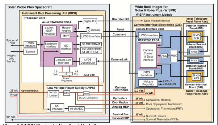
passes the commands to the WIM and receives the camera data from the WIM. The WIM controls the two cameras, receives the analog data, digitizes it to 14 bits, removes cosmic rays, and adds individual images together to increase SNR. The functional block diagram is shown in Figure 5. The IDPU is being developed by APL based on specifications provided by the NRL team. The WISPR Camera Interface Electronics (CIE) is an adaption of the SoloHI electronics. The data is transferred from WIM to IDPU via a Camera-Link interface, is compressed and packetized and is then transferred to the onboard Solid State Recorder via SpaceWire.
2.4 Testing and Modeling of High Speed Dust Impacts on the WISPR Optics
The orbital velocities at the SPP perihelia are very high (~170 km/s) and therefore the distribution of the kinetic energy of the dust particles and their fluence have to be accounted for in the WISPR design. The mass and size distributions are not known but models suggest that the majority of the particles will have diameters less than 10 microns. For example, the APL/UTEP model predicts about 100 impacts from 10 micron particles and 1000 impacts from 0.1 micron particles at the heat shield during the seven years of the mission. Dust impacts pose two risks for WISPR: (1) they can damage the edges of the forward baffles and thus increase the stray light levels and, (2) they can damage the front lens surfaces and lead to increased stray light by pitting and/or cratering the glass surface. Larger particles can of course break the lens but the probability of a catastrophic hit is exceedingly small (<10-5 for >1mm particle).
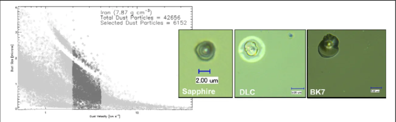
There is very little information on the effects of high velocity impacts on optical systems since such environments have not been encountered before. To understand the effects of dust on instrument performance, the WISPR team has established a glass testing and modeling program during the design phase as part of the contribution of the WISPR Co-I team in Germany (V. Bothmer, PI). Although there is no dust accelerator that can accelerate particles to 100s km/s velocities, the Dust Accelerator at the Max-Planck Institute für Kernphysik (MPIK) in Heidelberg is potentially capable of up to 60 km/s velocities. The facility was used in October 2012 to test three different candidate glass materials for the WISPR optics; BK7, BK7 with a diamond coating, and Sapphire. The tests were performed with a variety of iron particle distributions (0.5 – 3 microns) and speeds (0.5 - 8 km/s) against three different impact angles (0º, 45º, 70º) (shaded area in Figure 6).
The examination of the impacted glasses showed that sapphire was the most impact-resistant material with very small (2 microns) and symmetric crates. The diamond-coated BK7, on the hand, did not perform well. The impact caused a halo around the impact crate. We believe that the halo is the result of the detachment of the coating locally due to the heat produced by the impact. The regular BK7 has relatively small craters (~5 micron diameter). The spall diameters are very
consistent with the APL/UTEP model and give confidence in the overall SPP project dust analysis and rick mitigation procedures.
An automated software program was developed to measure the sized and numbers of craters in the images to assess the extent of the damaged area. The results (Figure 7) show a relatively linear damage increase with dust speed. Based on these results, we decided to adopt the regular BK7 as the baseline for the WISPR optics.
Figure 6 Left: The Size-Velocity distribution of the iron particles used in the WISPR Dust Impact experiment. Right: Examples of crater damage in the 3 glass types used in the experiment.
Figure 7 Left: The effect of dust fluence on percent damage area for the three glass types used in the WISPR Dust Impact experiment. The lines are simple linear fits to the data. Right: Fits to the BTDFs of pristine (blue curve) and damaged BK7 (red/green curves correspond to different samples). The data points are marked by crosses.
To study the effect on the imaging performance we then had to measure the change in the Bidirectional Scattering Distribution Function (BSDF) or Harvey-Shack function compared to the BSDF of the undamaged glass. So, we measured the Bidirectional Transmittance Distribution Function (BTDF) of the damaged glasses and used the percent damaged area to make a linear fit to the BTDF (Figure 7, right). The measurements revealed that the model BK7 used in FRED was too conservative. We adjust those curves and run our stray light calculations for pristine and damaged WISPR lenses to calculate the beginning- and end-of-life performance of the optics. The results are shown in Figure 8.
To summarize, the dust testing and subsequent analysis has allowed us to (1) validate the APL/UTEP model at those velocities and accepted for evaluating the risk for higher speeds, (2) reject exotic materials and coatings as an alternative to regular BK7, (3) develop a realistic BSDF model to evaluate the stray light effects of dust impacts on the imaging performance, and (4) get an estimate on the approximate damaged area of the WISPR optics. The team has kept the option open to return to MPIK for one more round of testing of either the flight glass or possibly a recently-identified ceramic glass material.
3. CONCLUSIONS
SPP will be mankind’s first probe in the atmosphere of a star and our first direct view of the interior structures of the corona without the interference by the F-corona. The rapid perihelia will provide a tomographic-like view of these structures and their proximity makes spatial resolution calculations just lower bounds. We do not really know what the WISPR images will uncover. The discovery possibilities are endless and this makes SPP one of the most exciting heliophysics missions ever. The WISPR program is still in its preliminary design phase with the review scheduled for November 2013 and the Critical Design Review scheduled for December 2014. There are no major concerns for the instrument at this point. The stray light is under control, the flight detectors have been fabricated, and the overall project is on schedule and within budget.
Figure 8 Left: Comparison of the estimated stray light levels at Beginning- (BOL) and End-Of-Life (EOL) for the WISPR instrument. The modeling is based on damage to 0.6% of the lens area as predicted by the dust model and uses BSDF measurements from the dusts tests at MPIK. The higher levels in the inner telescope are a result of the uch brighter scene at those elongations.
ACKNOWLEDGEMENTS
This work is sponsored by the NASA LWS program through interagency agreement NNG11EK11I
to NRL. The German contribution to WISPR is sponsored by the Deutsches Zentrum für Luft- und
Raumfahr (DLR). The Belgian contribution is sponsored by the Belgian Science Policy Office
(BELSPO).
REFERENCES
[1] Howard, R. A., et al., “Sun Earth Connection Coronal and Heliospheric Investigation (SECCHI)”, Sp. Sci. Rev., 136, 67-115, (2008)
[2] Müller, D, Marsden, R.G., St. Cyr, O.C., Gilbert. H.R.. “Solar Orbiter - Exploring the Sun-heliosphere connection”,
Solar Physics, in press (2013)
[3] Howard, A., et al., “The Solar And Heliospheric Imager (Solohi) Instrument For The Solar Orbiter Mission”, Proc.
SPIE, This Volume, (2013)