International Journal of Latest Research in Scienceand Technology ISSN (Online):2278-5299 Volume 5, Issue2: Page No.69-74, March-April 2016
http://www.mnkjournals.com/ijlrst.htm
ISSN:2278-5299 69
DESIGN AND MODELIZATION OF ACONVEX
GRATING FOR AN HYPERSPECTRAL IMAGER
OF THE CHANDRAYAAN 2 INSTRUMENT FOR
THE MOON PROBE IN THE INFRARED
Bernard Sabushimike1, Georges Horugavye1, Pierre Piron1, Jean François Jamoye2, Vincent Moreau2, Serge Habraken1 1 Holography and Optical laboratory (HOLOLAB), University of Liège, Belgium
2 AMOS, Liège Science Park, 2 Rue des Chasseurs Ardennais, B-4031 ANGLEUR, Belgium,
Abstract- For hyperspectral imaging, diffraction gratings based spectrometers exhibit high spectral resolution and optical performance. Among those spectrometers, the Offner type (which consists of an entrance slit, two concave mirrors and convex grating) offers a lot of advantages. In this paper, we propose the design and modelization of a convex grating which covers a spectral band ranging from 0.7 μm to 5 μm with a minimum diffraction efficiency of 20% at 800 nm, 50% at 3000 nm and 25% at 5000 nm. For a so wide band, a grating with a single blaze cannot satisfy these requirements. We will therefore propose an approach of multi-blaze grating which is subdivided into different sections each with its own blaze angle. Meanwhile, we perform the diffraction efficiency prediction using the scalar and rigorous theories to prove the compliance of this design with the technical specifications. The rigorous theory will also allow us to study the polarization sensitivity of this grating and the calculation of the diffraction efficiency of a grating with a profile degraded by manufacturing errors to assess the impact on the diffraction efficiency and the sensitivity to polarization.
Keywords-Offner spectrometer, grating, blazing, multi-blaze grating. I. INTRODUCTION
Hyperspectral remote sensing has been defined as “the field of study associated with extracting information about an object without coming into physical contact with it”[1]. It combines two sensing modalities: imaging and spectrometry. An imaging system captures a picture of a remote scene related to the spatial distribution of the power of reflected and/or emitted electromagnetic radiation integrated over some spectral band. On the other hand, spectrometry measures the variation in power with the wavelength or frequency of light, capturing information related to the chemical composition of the materials measured[2]. Our study focuses on this second part proposing a design of a convex grating for the hyperspectral imager spectrometer of the Chandrayaan 2[3] instrument which covers a spectral range from 0.7 μm to 5 μm with diffraction efficiency described in section IV.1. For spectrometry, an optical system with convex grating in Offner configuration demonstrates a high performance with a compact volume.
II. CONVEX GRATING SPECTROMETER IN OFFNER CONFIGURATION
An Offner grating spectrometer design requires the use of convex blazed grating that can be produced by ruling or diamond turning. It consists of a slit, two concave mirrors and a diffraction convex grating between them. Because of the asymmetry introduced by grating diffraction, a split-Offner design is employed, where orientation of the two mirrors is slightly asymmetric. This configuration offers a larger field of view and lower aberrations. These spectrometers have a concentric structure and thus a compact design. They operate with a relatively low F-number (≤f/2),
accept a long slit while maintaining a compact size, and need only three optical surfaces. The use of this design has resulted in imaging spectrometers with extremely low values of spatial-spectral distortion[4]. Most land observation hyperspectral instruments are based on Offner configuration. This is the case of the Hyperion instrument on board EO-1 NASA platform or HyspIR[5], but also for the imaging spectrometer for planetary mineralogy[6], EnMAP[7], CHRIS (on board proba-1)[8].
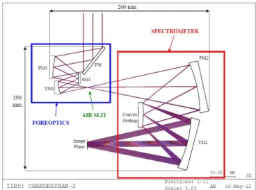
The present instrument (Chandrayaan 2) consists of a four optics telescope, slit, spectrometer, order sorting filter and detector. The instrument design is presented at figure 1.
Figure 1 : Hyperspectral instrument design (AMOS proprietary).
International Journal of Latest Research in Science and Technology
ISSN:2278-5299 70 III. GRATING DESCRIPTION
The grating description is summarized in the table 1. Table 1 grating specification related to Chandrayaan 2
mission[3]
Surface profile Convex spherical
Surface shape Circular
Clear aperture >37 mm Radius curvature 88.4±0.05 mm
Material Optical grade aluminium
Coating Gold
Groove density 20 grooves/mm Incidence angle of
the central field
27.12 degrees Optimization order +1
IV. DESIGN AND MODELIZATION OF THE CONVEX GRATING
IV.1.INTRODUCTION
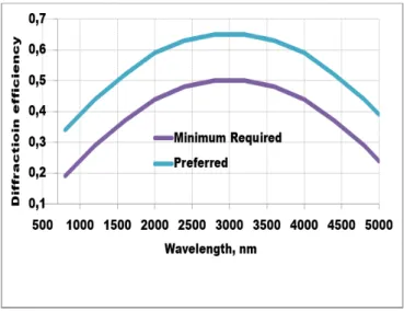
The grating specifications require a period of 50 µm with a spectral range of operation from 0.7 to 5 µm. Based on a preliminary study, we understand the challenge due to the wide spectral bandwidth. As a consequence, a multi-blazed grating is predicted as the only viable solution. The choice of blaze angles and the configuration are dictated by the required diffraction efficiency defined by figure 2.
Figure 2 : Diffraction efficiency requirement for the convex grating.
As far as modelling of surface-relief metallic gratings is concerned, an efficient tool is the PCGrate software based on a rigorous integral method of solving the electromagnetic problem[9]. Blazed gratings with TE and TM polarization on flat or non-flat substrate can be modeled and optimized. The diffraction efficiency over the diffraction orders is fully characterized. Numerical instabilities can arise, especially with large period as we find in this case.
For that reason, a simpler more intuitive approach is also possible since the grating period is large, compared to the wavelength: the “scalar theory” approach is another useful tool. Both tools will be used and compared to enhance the trust level of simulations. However, only the rigorous theory
will give information about the polarization sensitivity of the grating.
This paper will focus on the optimization of the Chandrayaan 2 diffraction grating. The goal is to fulfill the requirements, especially the spectral behavior of the diffraction efficiency and the polarization sensitivity. The proposed method consists in defining a “multi-blazed profile”and we will use both scalar and rigorous theories.
IV.2. Scalar theory
The scalar theory is very convenient. It is a theory that ignores the vectorial aspect of light but provides results comparable with those obtained with rigorous theories under specific conditions while being less time consuming and easier to implement. Moreover, the scalar theory allows for an easier approach to optimise diffraction gratings, while rigorous theories sound more like tools to check the diffraction characteristics for the gratings designed. The scalar theory is a powerful tool to deal with high period to wavelength ratio grating. Scalar theory is known to be accurate if[10], [11]
10
λ
Λ
≥
(1)Where Λ is the grating period and λ is the wavelength. For the Chandrayaan 2 hyperspectral imaging spectrometer, the wavelength range extents from 0.7 to 5 µm for a grating period of 50 µm. Even the worst case (50 µm/5 µ m) responds to the scalar theory criterion. This means that Fourier theory can be used. However, this model does not take into account the polarization state. The scalar diffraction efficiency for reflective gratings assuming a perfect reflective coating is given by[12]:
(2) Where k is the diffraction order and h is the grating thickness directly linked to the blazed wavelength:
2
bh
k
λ
=
(3)Therefore, for one given thickness when λ = λb, the grating achieves 100% diffraction efficiency at the diffraction order k. The diffraction efficiency will be zero for every other diffraction orders. Combining equations 2 and 3, the diffraction efficiency for the first order (k = +1) of diffraction becomes:
(4)
IV.3. Rigorous theory: “PCGrate software”
Our rigorous analysis tool allows calculating the diffraction efficiency of gratings on plane, spherical, cylindrical and aspherical surfaces. PCGrate uses an accurate boundary integral equation method, with some optimization parameters, which is described with numerous references directly on the website of PCGrate[13].
International Journal of Latest Research in Science and Technology
ISSN:2278-5299 71 IV.4. Diffraction efficiency and polarization sensitivity
IV.4.1. Profile construction
Using the rigorous theory, we simulated the grating performance with respect to the grating profile, departing from ideal triangular blazed profile.
Also, we know that the tooling can produce a default on the edges of the profile: the top edge being randomly flattened over 5 µm while the groove bottom being rounded with a radius of curvature of 5(10) µm over the last 3(5) microns for the less (more) rounded profile. The goal is to analyze the impact it can have on the grating diffraction efficiency as well as sensitivity to polarization. We constructed two types of realistic profiles (less and more rounded profiles) according to each of the blazing angles that are needed in the multi-blazed profile. The figure 3 shows an example of realistic profiles (less and more rounded) compared to the ideal blazed profile for a blaze wavelength of 3000 nm.
Figure 3: Ideal and realistic profiles used in the simulations for a blazing at 3000 nm (note that the ordinate is not at the
same scale as the abscise).
Figure4: Ideal and realistic profiles for a blazing at 3000 nm: at scale.
IV.4.2. Single blaze
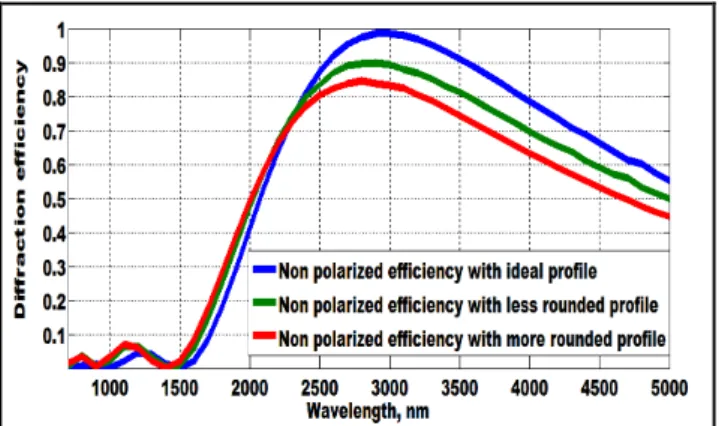
The next figures compare the diffraction efficiency spectral behavior computed with the scalar and the rigorous theories at a blaze wavelength of 3000 nm. Figures 5 depicts performance with respect to an ideal profile for scalar theory while figure 6 represents non polarized diffraction efficiencies given by rigorous theory for a perfect reflective grating with ideal, less and more rounded profiles.
Figure 5: Diffraction efficiency of the +1st diffraction order for a grating with a single blazing, at 3000 nm based on
scalar theory using ideal profile.
Figure 6:Non polarized diffraction efficiencies of the +1st diffraction order for a perfect reflective grating with a single blazing, at 3000 nm based on rigorous theory using ideal, less
and more rounded profiles (see figure 3).
As can be seen on both figures 5 and 6, results of the scalar theory are similar to those of the rigorous theory for ideal profile. If we compare the ideal and realistic profiles (figures 6), the maximum diffraction efficiency decreased by 16% from ideal to more rounded profile with a slight shift to the lower wavelengths. This decrease is significant and can be important if the profile rounding is important. But the most important conclusion is that one cannot cover the entire band requirement with a single blaze grating.
IV.4.3. Multi-blazed grating
The previous results show that one cannot reach the desired diffraction efficiency over the entire band with a single profile grating. To overcome this problem, a multilevel diffraction grating (figure 7) can be used in order to mix diffraction efficiency spectra and reach an average multilevel diffraction efficiency with higher homogeneity in accordance with the technical specifications.
International Journal of Latest Research in Science and Technology
ISSN:2278-5299 72 The multilevel gratings can be defined over a period[11],
[14], [15], [16] but in our case, the hybrid grating profile might be built as an ensemble of sub-gratings (sections) each with its blaze angle at fix period and fix draft angle α (often assumed as zero). It means that the groove depth h is increasing when the blazing angle ϒ increases as shown on figure 8.
Figure 8: Influence of the blaze angle γ on the grooves depth h with a draft angle α.
During the manufacture of the multi-blaze grating, it is obligatory to change the slope of the diamond cutting tool to change the blaze angle and the depth passing from one section to the other. In this case, the rulings between different blazes will tend to match at the peaks and the difference between the average heights will be high. Therefore the mean phase difference is considerably large[17]. This would have a detrimental effect on the point spread function (PSF). The ideal solution is to match the mean heights thus leading to a zero mean phase difference between the blazes.
We will first use the scalar theory to demonstrate the feasibility of this technique and determine the blaze geometries that can be implemented in the software tool
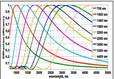
PCGrate, better suited to apply all technical specifications of the grating. In figure 9, each curve corresponds to a single blazing, centered at a specific blaze wavelength. The legend specifies the selected blaze wavelengths. Once more, the desired diffraction efficiency cannot be reached over the entire band with a single blaze. The simulation shows that a nine blazing profiles grating has a smooth diffraction efficiency curve with the desired diffraction efficiency (figure 10).
Figure 9: Diffraction efficiency for nine ideal blazing profiles, corresponding to nine blaze wavelengths as shown
on the legend, given by scalar theory.
Figure 10: Diffraction efficiency of multi-blazed grating with ideal profiles given by scalar theory compared to the
minimum required.
Using the rigorous theory, we built 9 blazing profiles (ideal and realistic) as described in section IV.4.1 and we modeled a grating with 9 sections each with its own blaze wavelength.
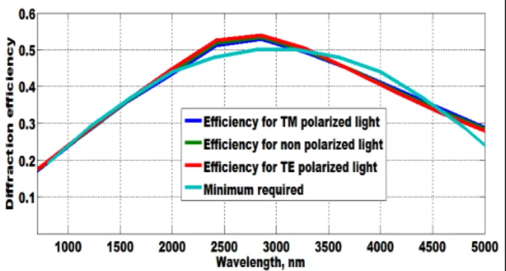
Figures 11, 12 and 13 show the diffraction efficiencies of the multi-level grating using respectively ideal, less and more rounded profiles, with the grating parameters given in the table 1, and the comparison with the required performance of the grating. We note that the diffraction efficiency of the multi-blazed grating, given by rigorous theory for ideal profile, is obviously similar to that given by scalar theory.
Figure 11: Diffraction efficiency for the multi-blazed grating given by rigorous theory using ideal profiles with the grating
parameters given in the table 1.
Figure 12: Diffraction efficiency for the multi-blazed grating given by rigorous theory using less rounded realistic profiles
International Journal of Latest Research in Science and Technology
ISSN:2278-5299 73 Figure 13: Diffraction efficiency for the multi-blazed grating
given by rigorous theory using more rounded realistic profiles with the grating parameters given in the table 1. The comparison between the realistic and ideal profiles (figures 11, 12 and 13) shows that diffraction efficiency decreases with rounded profiles. A loss of 5% is remarkable through the ideal profile to more rounded profile especially in the middle infrared.
An important drawback when using grating as dispersive element is the relatively large polarization sensitivity i.e. the diffraction efficiency is different for TM and TE polarization. This difference depends on the incidence angle, wavelength and spatial frequency of the grating. The polarization sensitivity of the grating can be studied with the rigorous theory. The equation 5 calculates that dependency as the contrast or degree of polarization:
(5) Where and are respectively the diffraction efficiencies for TE and TM polarized light.
The polarization dependency of this multi-blazed grating can be deduced from the curves of figures 11, 12 and 13. Figure 14 depicts that dependency as the contrast or degree of polarization for ideal and realistic profiles. In the case of the Chandrayaan 2 hyperspectral imager, the polarization contrast of the grating should remain below 5%. This requirement is met over almost the whole spectral band by the realistic profiles and more than 80% of the band by the ideal profile.
Figure 14: Polarization contrast of the +1st diffraction order for a multi-blazed grating based on rigorous theory using
ideal and realistic rounded profiles.
If the realistic profile decreases the diffraction efficiency, it also reduces the polarization contrast. The polarization contrast decreased from 7.2% for the ideal profile to less than 2 % for the more rounded profile especially in the middle infrared where the sensitivity is the highest. The computation proves that a way to reduce the polarization contrast consists in adapting a smoother grating profile. Within the desired diffraction efficiency, a shape flattened at the top and a rounded bottom of the grooves reduces the effect of polarization sensitivity. Such a profile is also closer to manufacturing capability.
IV.5. Diffraction efficiency as a function of incidence angle
Since the multi-blaze grating is convex, the incidence angle of an almost collimated wavefront varies along its surface. For an incidence of 27.12 degrees at the grating center, the incidence angles at left and right ends are respectively 15.04 and 39.20 degrees.
Consequently, the diffraction efficiency of multi-blaze grating with ideal profile as a function of the incidence angle is studied below. The simulation is performed at a wavelength of 3000 nm. The diffraction efficiency slowly varies as a function of incidence angle under 40 degrees (figure 15).
Figure15: Diffraction efficiency for the multi-blazed grating, as a function of incidence angle, given by rigorous theory
using the ideal profile. The red line indicates the ideal incidence angle (27.12 degrees).The black and green lines
indicate respectively the incidence angles at left (15.04 degrees) and right (39.19 degrees) edges of the grating. The polarization contrast as a function of the incidence angle is given by thefigure 16.
International Journal of Latest Research in Science and Technology
ISSN:2278-5299 74 Figure 16: Polarization contrast of the +1st diffraction order
for a multi-blazed grating, as function of incidence angle, based on rigorous theory using ideal profile. The red line indicates the ideal incidence angle (27.12 degrees). The black
and green lines indicate respectively the incidence angles at left (15.04 degrees) and right (39.19 degrees) edges of the
grating.
As can be seen, the polarization contrast of multi-blaze grating remains far below the required value of 5% inside working limits.
V. CONCLUSION
The results obtained with single blaze have shown that such diffraction grating cannot cover a spectral range from 0.7 microns to 5 microns with the required diffraction efficiency. Consequently, we proposed a nine (9) sections multi-blaze grating each with its own blaze wavelength: 700, 1000, 1400, 1800, 2200, 2500, 3000, 3300 and 4400 nm. The calculation of the diffraction efficiency using both rigorous and scalar theories has shown that such conception is covering the given spectral band with efficiency matching the required specifications. Unfortunately the diffraction gratings exhibit a non-negligible sensitivity to polarization. We also showed the impact of a rounded profile as encountered with practical manufacturing techniques: the diffraction efficiency decreases with rounded profiles but the polarization sensitivity is also reduced especially in the mid infrared. We also calculated the degree of polarization of multi-blaze depending on the angle of incidence for a wavelength of 3000 nm. The results show that when the angle of incidence remains inside the working limits, the polarization contrast remains low.
REFERENCES
1. J. R. Schott, Remote sensing: the image chain approach. Oxford University Press, Oxford, New York, 2007.
2. M. T. Eisman, Hyperspectral Remonte Sensing, vol. PM210. Bellingham, Washington 98227-0010 USA: SPIE press, 2012. 3. Indian Space Research Organisation, “Chandrayaan - 2.” Online].
Available: http://www.isro.gov.in/chandrayaan-2.
4. V. Moreau, C. Declercq, J.-F. Jamoye, and A. Z. Marchi, “Free-Form Diffraction Grating for Hyperspectral Imager,” 4S
Symposium 2014, Liège, pp. 1–9, 2014.
5. J. F. Silny and T. G. Chrien, “Large format imaging spectrometers for future hyperspectral Landsat mission,” Proc. SPIE, Imaging
Spectrom. XVI, vol. 8158, no. 815803, pp. 1–26, 2011.
6. P. Mouroulis, R. G. Sellar, D. W. Wilson, J. J. Shea, and R. O. Green, “Optical design of a compact imaging spectrometer for planetary mineralogy,” Proc. SPIE, Opt. Eng., vol. 46, pp. 1–9, Jun. 2007.
7. B. Sang, J. Schubert, S. Kaiser, V. Mogulsky, C. Neumann, K.-P.
Förster, S. Hofer, T. Stuffler, H. Kaufmann, A. Müller, T. Eversberg, and C. Chlebek, “The EnMAP hyperspectral imaging spectrometer : instrument concept , calibration and technologies,”
Proc. SPIE, Imaging Spectrom. XIII, vol. 7086, no. 708605, pp. 1–15, 2008.
8. M. Barnsley, J. Settle, M. Cutter, D. Lobb, and F. Teston, “The PROBA/CHRIS Mission: A low-cost smallsat for hyperspectral, multi-angle, observations of the Earth surface and atmosphere,”
IEEE Trans. Geosci. Remote Sens., vol. 42, no. 7, pp. 1512–1520, 2004.
9. International Intellectual Group, “PURPOSES AND TASKS.” [Online]. Available: www.iigrate.com.
10. J. Francés, C. Neipp, S. Gallego, S. Bleda, A. Márquez, I. Pascual, and A. Beléndez, “Comparison of simplified theories in the analysis of the dif- fraction efficiency in surface-relief gratings,” in Proc. SPIE , Optical Modelling and Design II, 2012, vol. 8429, pp. 1–10.
11. V. Raulot, “Méthodes de conception et de fabrication de dispositifs imageurs en optique diffractive à structures sub- longueur d ’ onde,” Thesis presented for obtaining the degree of Doctor of Engineering Sciences, University of Strasbourg, 2011. 12. F. Languy, “Achromatization of nonimaging Fresnel lenses for
photovoltaic solar concentration using refractive and diffractive patterns,” Thesis presented for obtaining the degree of Doctor of Physical Sciences, University of Liège, 2012.
13. International Intellectual Group, “ACCURATE
ELECTROMAGNETIC THEORIES.” [Online]. Available: www.PCGrate.com.
14. I. A. Erteza, “Diffraction Efficiency Analysis for Multi-Level Diffractive Optical Elements,” Report of the Sandia National Laboratories for the United states Department of Energy , New Mexico, 1995.
15. M. Oliva, T. Harzendorf, D. Michaelis, U. D. Zeitner, and a Tünnermann, “Multilevel blazed gratings in resonance domain: an alternative to the classical fabrication approach.,” Opt.
Express, vol. 19, no. 15, pp. 14735–45, Jul. 2011.
16. E. C. ép. Neiss, “Mise en forme de faisceaux de lasers de puissance dans le proche infrarouge par éléments diffractifs,” Thesis presented for obtaining the degree of Doctor of Engineering Sciences, Louis Pasteur University- Strasbourg I, 2008.
17. P. Mouroulis, D. W. Wilson, R. E. Muller, and P. D. Maker, “New convex grating types for concentric imaging spectrometers .,” Appl. Opt., vol. 37, no. 31, pp. 7200–7208, 1998.