UNIVERSITÉ DE MONTRÉAL
INVESTIGATION ON THE MIXING PERFORMANCE IN A SUPERBLEND
COAXIAL MIXER
XIAO WANG
DÉPARTEMENT DE GÉNIE CHIMIQUE ÉCOLE POLYTECHNIQUE DE MONTRÉAL
THÈSE PRÉSENTÉE EN VUE DE L’OBTENTION DU DIPLÔME DE PHILOSOPHIAE DOCTOR
(GÉNIE CHIMIQUE) MARS 2014
UNIVERSITÉ DE MONTRÉAL
ÉCOLE POLYTECHNIQUE DE MONTRÉAL
Cette thèse intitulée:
INVESTIGATION ON THE MIXING PERFORMANCE IN A SUPERBLEND
COAXIAL MIXER
présentée par: WANG Xiao
en vue de l’obtention du diplôme de : Philosophiae Doctor a été dûment acceptée par le jury d’examen constitué de : M. BERTRAND François, Ph.D., président
M. TANGUY Philippe A., Ph.D., membre et directeur de recherche M. FRADETTE Louis, Ph.D., membre et codirecteur de recherche M. TAVARES Jason-Robert, Ph.D., membre
Dedicated to my dad and my mom
ACKNOWLEDGEMENTS
There is a Chinese saying says: do not say ’thank you’ if one received an enormous kindness from the other. Indeed, the two words are too plain to express my gratitude to these people for their consistent supports and encouragements.
Dr Tanguy, my mentor, brought me to URPEI. We first met in Beijing in 2008. He was invited by Bruce Gao, my previous supervisor, who guided me to the world of mixing, for a mixing speech in my previous university, Beijing University of Chemical Technology. If I have to name some people that I really worship, he is always the one on the top. Every time he talks to me, it is like opening a door to another world in my face. I am so desperate for hearing the intriguing industrial experiences he has gained through his world tours. I always ponder that when and how I could be like him. Frankly, I do not expect to catch up with him, but I believe with all my efforts I can get closer to him step by step.
Dr Fradette, my mentor, has been guiding and inspiring me ever since the first day we met. This gentleman told me on that day: ‘My office door is always open for you’, but I didn’t expect he was serious. In the passing years every time I need help and support from him, he is always ready for helping me out with his ‘power-cube’ filled with innovation and erudition, no matter where he is and when it is. No wonder all my friends at Poly envy me so much for being his student. I know he knows he is wonderful, like everybody does.
Dr Bertrand, the mentor of every student in URPEI, has been caring and encouraging me in the past years. The greatest lesson he has taught me is not GCH 6914, but an advice he gave us in the course: ’if one wants to learn something, just go teach it.’ This advice is very useful, and I indeed give the credit to him every time I cite it.
Dr Kresta, the jury member for my Ph. D proposal, has been concerning about my study progress all the time. She gave me a broad vision for mixing and shared with me the cool things occurred in industry.
Dr Inci Ayranci, the co-author of my two papers, has been my teacher and good friend ever since she came to URPEI. Having her around, I don’t need to look up the reference on solid-liquid mixing anymore. I sincerely appreciate her understanding and suggestions during our discussions on my research and the chaotic ideas in my head. Best wishes for her bright future.
Émir, my close colleague, the translator of the abstract, has been a good accompany both in the office and laboratory. His attitude to the experiment and research has been inspiring me, and his food supply to me is also an important support for my hard working.
There are still so many people I would love to list, including my dear colleagues in URPEI, the teachers, technicians and administrative staff in department and all my dear friends at Poly. All the accomplishments I have obtained so far belong to them as well.
RÉSUMÉ
Le mélange est une opération unitaire très courante dans les procédés industriels qui trouve son application dans divers domaines tels que la dispersion de liquides, la suspension de solides, les réactions chimiques (polymérisation, fermentation…) et d’autres applications. Par ailleurs, dans beaucoup de cas impliquant des systèmes monophasique ou multiphasique, d’importantes variations de la viscosité peuvent être observées durant le procédé en raison des comportements rhéologiques complexes des systèmes mis en jeu. Cela se traduit notamment par une très grande déviation par rapport aux principes considérés lors de la conception d’un mélangeur standard. Ainsi, le choix d’un type de mélangeur pouvant assurer une efficacité élevée tout au long du procédé peut être une opération relativement complexe nécessitant beaucoup d’innovation. Dans cette optique, différents types de mélangeurs ont été considérés dont le mélangeur coaxial « Superblend » qui a donné les résultats extrêmement prometteurs. Ce mélangeur se compose de deux agitateurs : Un ruban hélicoïdal et un Maxblend. Ainsi, grâce à cette combinaison, différentes conditions de fonctionnement peuvent être considérées dans un seul récipient pour faire face aux problèmes liés aux comportements rhéologiques complexes des fluides mis en jeu. Ayant pour objectif d’apporter plus de compréhension des performances de mélange, des principes de conception et des lignes directrices des opérations de scale up de ce type de mélangeur, une caractérisation complète de l’hydrodynamique du Superblend a été réalisé en considérant des fluides Newtonien et non-Newtoniens dans des systèmes monophasique ou multiphasique. Les résultats obtenus ont montré que le champ d’écoulement, les performances de mélange en termes de puissance consommée et de temps de mélange ainsi que la contribution de chaque agitateur dépendaient fortement du comportement rhéologique, de la taille des particules et de leur concentration dans les suspensions de solides, du rapport de vitesse des agitateurs ainsi que du mode de rotation. La vitesse caractéristique proposée par Farhat et al. (2008) pour les mélangeurs coaxiaux a notamment été appliquée à d’autres mélangeurs multi-arbres qui n’ont pas été considérés dans les précédents travaux et le domaine d’application et limitations ont été discutés. Ainsi, en comparant les résultats avec les données disponibles, la puissance consommée, le temps de mélange et l’énergie de mélange de différents types de mélangeurs ont été présentés et une approche globale pour prédire la puissance consommée des mélangeurs multi-arbre a été proposée. En conclusion, il a été trouvé que le Superblend surclassait tous les autres mélangeurs en termes de temps et d’énergie de mélange.
ABSTRACT
Mixing is a ubiquitous unit operation in the process industries with numerous applications in reaction (polymerization, fermentation), distribution of solids and liquids, and blending (manufacturing of formulated products). In many cases of single-phase and multi-phase systems, widely and rapidly varying viscosities over the processing time occur along with the development of complex rheological behaviors. Since there is a huge gap between the design principle of the standard mixing approach and the mixing mechanism in rheologically complex systems, the resulting mixing inefficiencies have roused the innovations in mixer design and optimization. Among a variety of equipments and geometries designed to fill this gap, a recently emerged mixer concept Superblend coaxial mixer is one of the very promising candidates. Superblend coaxial mixer consists of two impellers: a helical ribbon as outer impeller and a Maxblend impeller as inner impeller. This combination allows a synergy between impeller geometries in different operating conditions in a single vessel to tackle the problems in rheologically complex mixing. Aiming at providing comprehensive scientific information on mixing performance, process design principles and scale-up guidelines, a full characterization of the single-phase and multiphase hydrodynamics in the Superblend mixer with both Newtonian and non-Newtonian fluids was carried out. Results exhibited that various experimental parameters such as rheological behavior, particle size and concentration, speed ratio and rotating mode have significant influence on the mixing performance in terms of flow pattern, power consumption, mixing time and evolution, contribution of each impeller and the optimal operating conditions.
New definition of characteristic speed proposed by Farhat et al. (2008) for coaxial mixers were extended to some other multi-shaft mixers not considered in previous works, and the applicability and limitations were discussed. Based on the comparison and analysis of existing resource, the power consumption, mixing time and mixing energy of different mixers were presented and a general approach to predict the power consumption in multi-shaft mixer was introduced. The Superblend mixer outperforms all the other mixers from the perspective of mixing time and mixing energy despite the lack of power-efficiency.
TABLE OF CONTENTS
DEDICATION ... iii
ACKNOWLEDGEMENTS ... iv
RÉSUMÉ ... vi
ABSTRACT ... vii
TABLE OF CONTENTS ... viii
LIST OF TABLES ... xii
LIST OF FIGURES ... xiii
LIST OF SYMBOLS AND ABBREVIATIONS ... xvii
CHAPTER 1: INTRODUCTION ... 1
1.1 Mixing research ... 1
1.2 Structure of the thesis ... 3
CHAPTER 2: LITERATURE REVIEW ... 4
2.1 Mixing theory of highly viscous fluid ... 4
2.2 Maxblend ... 5
2.3 Dual shaft mixers ... 6
2.4 Coaxial mixers ... 8
2.5 Superblend ... 12
2.6 Solid-liquid mixing ... 13
2.6.1 Solid-liquid suspension ... 13
2.6.2 Distribution and dispersion in the solid-liquid mixing ... 15
2.6.3 Previous investigations on solid-liquid mixing ... 16
2.7 Literature summary and contributions of this thesis ... 20
2.8.1 General objective ... 21
2.8.2 Specific objectives ... 21
CHAPTER 3: ARTICLE 1: EFFECT OF OPERATING PARAMETERS ON THE MIXING PERFORMANCE OF THE SUPERBLENDTM COAXIAL MIXER ... 23
3.1 Abstract ... 23
3.2 Introduction ... 23
3.3 Experimental methods ... 25
3.4 Results and discussion ... 28
3.4.1 Overall Flow Pattern ... 28
3.4.2 Mixing Time ... 30
3.4.3 Power Consumption of the Superblend ... 33
3.4.4 Power Split ... 34
3.5 Conclusion ... 40
3.6 Acknowledgement ... 41
3.7 Reference ... 41
CHAPTER 4: ARTICLE 2: ANALYSIS OF POWER CONSUMPTION IN MULTI-SHAFT MIXERS ... 44
4.1 Abstract ... 44
4.2 Introduction ... 44
4.3 Materials and methods ... 45
4.4 Results ... 48
4.4.1 Discussion on Power Correlation ... 48
4.4.2 Extensions of the Applicability of the Power Correlations ... 50
4.4.3 Performance Comparison ... 53
4.6 Acknowledgement ... 61
4.7 Reference ... 62
CHAPTER 5: ARTICLE 3: EXTENDED CHARACTERIZATION OF THE SUPERBLENDTM COAXIAL MIXER WITH SHEAR-THINNING FLUIDS ... 65
5.1 Abstract ... 65
5.2 Introduction ... 65
5.3 Setup and Materials ... 67
5.4 Methodology ... 69
5.5 Results & Discussion ... 71
5.5.1 Mixing Evolution ... 71 5.5.2 Mixing Time ... 76 5.5.3 Power Consumption ... 81 5.5.4 Mixing Energy ... 87 5.6 Conclusion ... 92 5.7 Acknowledgement ... 92 5.8 Reference ... 92
CHAPTER 6: ARTICLE 4: SOLIDS DISTRIBUTION IN A SUPERBLEND COAXIAL MIXER USING ELECTRICAL RESISTANCE TOMOGRAPHY CHARACTERIZATION ... 95
6.1 Abstract ... 95
6.2 Introduction ... 95
6.3 Experimental methods ... 97
6.4. Results and discussion ... 104
6.4.1 Homogenization speed ... 104
6.4.2 Dimensionless mixing time ... 110
6.5 Conclusion ... 118
6.6 Reference ... 118
CHAPTER 7: GENERAL DISCUSSION, CONCLUSION AND RECOMMENDATIONS ... 121
7.1 General discussion ... 121
7.2 Conclusion ... 121
7.3 Recommendations ... 124
REFERENCE ... 125
LIST OF TABLES
Table 2.1: The influence of power input and operating conditions on the situation of solid-liquid
suspension. (Oldshue, 1983) ... 16
Table 3.1: Geometrical variables of the helical ribbon impeller ... 26
Table 3.2: Fitted parameters of equation (3.7) ... 32
Table 4.1: The comparison of KP for multi-shaft mixers ... 54
Table 5.1: Rheological properties of the studied shear-thinning fluids ... 69
LIST OF FIGURES
Figure 1.1: Conventional mixing setup and the cavern it causes ... 2
Figure 2.1: The schematic of mixing in laminar regime ... 4
Figure 2.2: Schematic of the Maxblend (Arash Iranshahi et al., 2007) ... 5
Figure 2.3: The configuration of a dual shaft mixer. (Barar Pour et al., 2007) ... 7
Figure 2.4: Geometries of two different dual shaft mixers. (Cabaret et al., 2007) ... 7
Figure 2.5: The schematic of coaxial mixer. (Tanguy and Thibault, 1997) ... 8
Figure 2.6: Experimental setup. (Thibault et al., 2002) ... 9
Figure 2.7: Experimental system. (Foucault et al., 2004) ... 10
Figure 2.8: Influence of turbine diameter on the mixing time. (Farhat et al., 2008) ... 12
Figure 2.9: Configuration of the Superblend mixer. ... 13
Figure 2.10: Different situations of suspension. ... 13
Figure 2.11: Difference between dispersion and distribution ... 15
Figure 2.12: Power consumption evolution in solid-liquid dispersion. (Barar Pour et al., 2007) . 17 Figure 2.13: The influence of different factors on the solid-liquid dispersion: ... 18
Figure 2.14: Tomogram of conductivity ... 19
Figure 3.1: Configuration of the Superblend mixer. ... 25
Figure 3.2 A: Expected flow field from the individual impellers in the Superblend ... 29
Figure 3.2 B: Expected flow field generated in the Superblend ... 29
Figure 3.2 C: Observed flow field generated in the Superblend ... 30
Figure 3.3: Influence of operation parameters on dimensionless mixing time. ... 31
Figure 3.4: Experimental results obtained under different speed ratios and rotating modes: (a) up-pumping of the helical ribbon and co-rotation of the Maxblend; (b) down-up-pumping of the helical ribbon and counter-rotation of the Maxblend. ... 34
Figure 3.5: Power curves of the helical ribbon: (a) up-pumping of the helical ribbon and co-rotation of the Maxblend; (b) down-pumping of the helical ribbon and counter-co-rotation of
the Maxblend. ... 35
Figure 3.6: Power curves of the Maxblend impeller: (a) up-pumping of the helical ribbon and co-rotation of the Maxblend; (b) down-pumping of the helical ribbon and counter-co-rotation of the Maxblend. ... 37
Figure 3.7: Maxblend power consumption to the total power expensed. ... 38
Figure 3.8: Influence of speed ratio and rotating mode on KP. ... 40
Figure 4.1: Coaxial mixer used in the work of Farhat et al.: (a) Rushton turbine; (b) Mixel TT .. 46
Figure 4.2: Dual shaft mixer used in the work of Barar Pour et al.: ... 47
Figure 4.3: Superblend coaxial mixer experimental setup ... 47
Figure 4.4: Flow patterns (tangential velocity, m/s) for the Rushton-Anchor configuration, ... 50
Figure 4.5: Power curve for the Deflo-Paravisc dual shaft ... 51
Figure 4.6: Power curve for the Mixel TT-Paravisc dual shaft ... 52
Figure 4.7: Power curve for the Superblend using the new correlations (Farhat et al.) ... 53
Figure 4.8: Dimensionless mixing time comparisons for all mixers ... 56
Figure 4.9: Dimensionless mixing energy comparisons for all mixers ... 58
Figure 4.10: Power curve for the Rotor Stator-Paravisc dual shaft using the new correlations .... 59
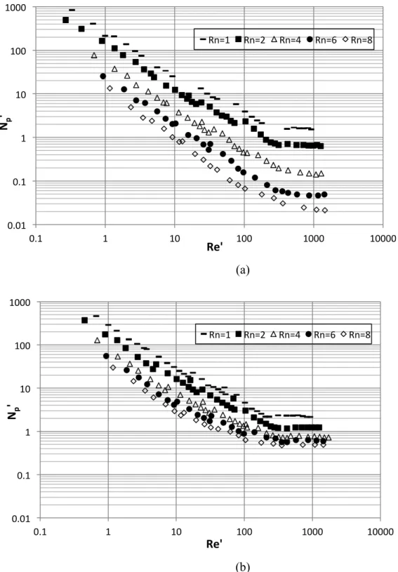
Figure 4.11: Power curves of Superblend mixer using the new correlations (NP’ and Re’ are equivalent with NP and Re presented in this work): (a) co-rotating mode; (b) counter-rotating mode. (Wang et al., 2012) ... 60
Figure 5.1: Configuration and dimensions of Superblend mixer ... 68
Figure 5.2: Decolorization images of mixing evolution in down-pumping mode ... 72
Figure 5.3: Decolorization images of mixing evolution with two fluids in up-pumping mode ... 74
Figure 5.4: Mixing curves for all the operating conditions at Ni = 80 rpm and No = 10 rpm ... 75
Figure 5.6: Influence of rheological behavior on mixing time ... 80
Figure 5.7: Effect of the speed ratio on the power consumption ... 82
Figure 5.8: The effect of speed ratio, rotating mode and power-law index on KP ... 84
Figure 5.9: The effect of power-law index on KP of the helical ribbon ... 84
Figure 5.10: The effect of power-law index on KP of the Maxblend impeller ... 85
Figure 5.11: The effect of speed ratio, rotating mode and power-law index on KS ... 87
Figure 5.12: Influence of speed ratio and rotating mode on mixing energy ... 90
Figure 5.13: Influence of rheological behavior on mixing energy ... 91
Figure 6.1: Superblend mixer and installation of electrodes ... 98
Figure 6.2: Resistivity evolution measured by ERT with 20 wt% particles of 500 µm in the liquid of 0.1Pa.s at Nhelical ribbon = 20 rpm: (a) response on the variation of solids distribution; (b) determination of tH ... 103
Figure 6.3: Effects of solids concentration, rotating mode, and the speed of the helical ribbon on the homogenization speed for 500 µm particles in 4 Pa.s liquid ... 105
Figure 6.4: Effects of the solids concentration, operating mode, and the speed of the helical ribbon on the homogenization speed of coarse particles (500 µm) in low viscosity liquid (0.1 Pa.s) ... 107
Figure 6.5: Experimental observation of the blocking effect in the up-pumping mode at NMaxblend = 80 rpm, Nhelical ribbon = 30 rpm ... 108
Figure 6.6: The influence of the variables on the homogenization speed of fine particles (75 µm) in low viscosity liquid (0.1 Pa.s) ... 109
Figure 6.7: Effects of the speed of the helical ribbon, liquid viscosity and solids concentration on the homogenization speed with 500 µm particles. (a) up-pumping, (b) down-pumping ... 110
Figure 6.8: Effects of solids concentration, particle size, operating mode, and speed of the helical ribbon on the dimensionless mixing time. (a) 500 µm particles in 4 Pa.s liquid, (b) 500 µm particles in 0.1 Pa.s liquid, (c) 75 µm particles in 0.1Pa.s liquid ... 113
Figure 6.9. The comparison of mixing time at homogenization speed in single-phase and solid-liquid systems at Nhelical ribbon = 10 rpm and NMaxblend (NH) varying between 60 and120 rpm.
(a) up-pumping mode, (b) down-pumping mode ... 115 Figure 6.10: Effects of solids concentration, particle size, operating mode, and speed of the helical ribbon on energy for homogenization. (a) 500 µm particles in 4 Pa.s liquid, (b) 500 µm particles in 0.1Pa.s liquid, (c) 75 µm particles in 0.1 Pa.s liquid ... 117
LIST OF SYMBOLS AND ABBREVIATIONS
Roman letters
c Clearance between the ribbon and tank wall (m) D Impeller diameter (m)
Dhelical ribbon Diameter of helical ribbon (m)
Di Diameter of the inside impeller (m)
DMaxblend Diameter of Maxblend impeller (m)
Do Diameter of the outside impeller (m)
Ds Shaft diameter (m)
Emix Mixing energy (-)
h Height of helical ribbon (m)
H Liquid height (m)
I Electrical current (I) G’ Storage modulus (-) k Consistency index (-)
K Geometrical parameter (1/m) KP Power constant (-)
KP’ Characteristic power constant (-)
KP’Total Total characteristic power constant of Superblend (-) KS Metzner constant (-) L Blade length (m) M Torque (N·m) Mc Corrected torque (N·m) Mm Measured torque (N·m) Mr Residual torque (N·m) n Power-law index (-) nb Number of blades (-) N Rotational speed (1/s)
N’ Characteristic rotational speed (1/s)
Nco-rotating Rotational speed in co-rotating mode (1/s)
Nhelical ribbon Rotational speed of helical ribbon (1/s)
NH Homogenization speed (rpm)
Ni Rotational speed of inside impeller (1/s)
Njs Just suspended speed (1/s)
NMaxblend Rotational speed of Maxblend impeller (1/s)
No Rotational speed of outside impeller (1/s)
NP’ Characteristic power number (-)
p Pitch (m)
P Power consumption (W)
Phelical ribbon Power consumption of helical ribbon (W)
PMaxblend Power consumption of Maxblend impeller (W)
PSuperblend Power consumption of Superblend (W)
Pv Specific power consumption (W/m3)
R Resistance (Ω)
Re Reynolds number (-)
Reliquid Reynolds number of the liquid (-)
Reη Reynolds number for shear-thinning fluids (-)
Re’ Characteristic Reynolds number (-)
Re’η Characteristic Reynolds number for shear-thinning fluids (-)
RN Speed ratio Ni / No
t Time (s)
tH Mixing time for homogenization (s)
tm Mixing time (s)
T Tank diameter (m)
Vø Hindered settling velocity (m/hour) w Blade width (m) wt% Weight percentage Greek letters ρ Density (kg/m3) ρ Resistivity (Ω /cm) a Dependence constant (-) λ Time constant (-)
ρliquid Liquid density (kg/m3)
ρs Solid density (kg/m3)
µ Viscosity (Pa.s)
µliquid Liquid viscosity (Pa.s)
µa Apparent viscosity (Pa.s)
𝛾 Shear rate (1/s)
𝛾av Average shear rate (1/s)
σ Electrical conductivity (S/m)
Θ Dimensionless mixing time
Θ0 Plateau value of Θ at low Reynolds number
Abbreviations
CFD Computational fluid dynamics CMC Carboxymethylcellulose
ERT Electrical resistance tomography LBP Linear back projection
OAT Optical attenuation technique PIV Particle image velocimetry rpm Revolutions per minute
CHAPTER 1: INTRODUCTION
1.1 Mixing research
Mixing operations are widely used in chemical engineering industry as well as biotechnology, and environmental remediation. The efficiency of mixing is associated with the results of the corresponding process and the cost of products. Meanwhile, mixing is also a unit operation that not fully-developed in the theoretical research, which leads user to more rely on the practical experience. For different operation occasions, even for analogical operation purpose, different mixing setups are basically applied. Due to the lack of the common standard for the comparison between the performances of equipments, it causes the huge inconvenience to determine the most effective approach for specified mixing task.
Therefore, the design of mixing installation becomes the key on the evaluation of a new technology or even a new production line. A proper design of agitation system is capable of diminishing the investment, decreasing the production cost, and obtaining the satisfactory process results. However, all this is based on the good understanding of mixing theory and being familiar with the rich experience and important research achievement that the previous researcher have accumulated up to now.
The mixing has been studied systematically as an individual unit operation for merely 60 years. In 1950’s, the theoretical foundation of mixing was built on the basis of fluid dynamics and mass transfer principles by dimension analysis and similarity theory. Nevertheless, the similarity theory was unable to touch the core to this complex process, which resulted in the lasting problem that the design and scale-up of mixing system could not be handled in a content manner. As the further development of mixing theory, the study on the turbulent phenomenon has partly discover the essential of mixing process. Especially in the past two decades, the theoretical research has improved remarkably benefiting from the innovative research method, for example CFD (computational fluid dynamics), and experimental techniques such as PIV (Particle Image Velocimetry). Although it is impossible to establish a new system of mixing theory, certain latest research achievement has already been utilized for the more reasonable design and scale-up.
Due to the development of the industrial demands, however, fluids mixing with diverse viscosities and rheological behaviors such as shearing-thinning effect, as well as homogeneous distribution of solids in liquids, keep arising in this field. Compared with the turbulent mixing, this kind of mixing process belongs to another system of mixing theory.
Referring to this case, if conventional mixing setup is used, which is characterized by a single or multiply impellers (as shown in Figure 1.1), it is obvious that the mixing performance and efficiency is unable to be satisfied, or even it is impossible to achieve the mixing effect. This is all because of the guideline that followed in the design process of these mixers.
Figure 0.1: Conventional mixing setup and the cavern it causes
As mentioned above, based on the relatively full development of turbulent theory, numerous mixers in industry are designed under turbulent theory, so that those mixers are merely suitable for the turbulent mixing. Therefore, a variety of drawbacks such as stagnancy, segregation, cavern and even mechanical damage are observed in the applications. It was reported that the overall consumption for such poor mixing was approximately $ 10 billion in the US chemical industry in 1989.
Being aware of this current situation, researchers throughout the world have started to study and design proper mixing setups for fluid mixing with complex rheological behavior and homogeneous solid-liquid distribution, which is also the emphasis of this work.
1.2 Structure of the thesis
This thesis is composed of seven chapters. The first chapter provides a general view of mixing research. Chapter 2 reviews the previous studies in multi-shaft mixers, and states the objectives of this investigation. Chapter 3 experimentally investigates the effect of operating parameters such as speed ratio and rotating mode on the power consumption and mixing time in the Superblend coaxial mixer with viscous Newtonian fluids. The highlights lie in the variation of flow patterns in different rotating mode, the power contribution of each impeller and the distinct optimal operating condition in each flow regime. Chapter 4 compares and analyzes the power consumption, mixing time and mixing efficiency of three types of multi-shaft mixers with Newtonian fluids, and assesses the applicability of new definitions of characteristic speed and diameter in a series of multi-shaft mixers. The Superblend mixer outperforms all other mixers based on comprehensive evaluation of both power consumption and mixing time. Chapter 5 extends the research to non-Newtonian fluid mixing, and thoroughly investigates the effect of speed ratio, rotating mode and rheological behavior on the power consumption, mixing time and mixing evolution in the Superblend mixer. A promising outcome is that the mixing efficiency of the Superblend mixer with non-Newtonian fluids even excels that with Newtonian fluids. Chapter 6 quantitatively explores the effect of particle size and concentration and operating parameters on the mixing performance of the Superblend mixer for homogeneous solids distribution with viscous Newtonian fluids. Chapter 7 generally discusses the conclusions on the results and technologies, and provides recommendations for the future researches.
CHAPTER 2: LITERATURE REVIEW
2.1 Mixing theory of highly viscous fluid
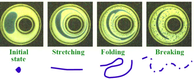
Being different from lowly viscous fluid mixing, due to the lack of diffusion phenomenon, the primary mixing principle of highly viscous fluid mixing is shearing mixing and convection mixing. The shearing effect produced by the impeller keeps stretching the target fluid (the cyan phrase) into thin flow layers. As the layers become thinner and thinner, the folding effect starts working. With the continuous stretching and folding actions, the target fluid finally gets broken and achieves the homogeneous mixing with the main fluid in the tank (the yellow phrase in Figure 2.1).
Figure 2.1: The schematic of mixing in laminar regime
With regard to the folding process in the highly viscous mixing, the existence of shear force is not sufficient as the driving force. Since the distribution of shear rate throughout the tank is not uniform, there is supposed to be a circulation effect that could transfer this shear force across the whole tank, namely the liquid elements in high shearing region and low shearing region should be exchanged continuously. The performance of this circulation will determine the efficiency of converting all the driving forces in this tank into effective driving forces.
To sum up, the performance of such mixing lies on whether sufficient shearing is generated near the impeller and the fluid in both high and low shearing regions can be fully circulated. Therefore, traditional mixing installations typified by a single impeller or multi-ply impellers can hardly deal with rheologically complex mixing with satisfying efficiency, restricted by bad regions, stagnancy, segregations and even complete failure of getting full-tank mixing. A variety of mixers are introduced to tackle viscous fluid mixing in a large variation range, such as dual shaft mixers, coaxial mixers, Maxblend and Superblend.
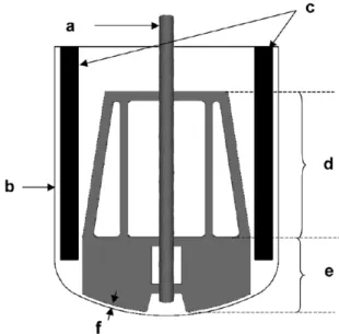
2.2 Maxblend
In the 1990’s, a wide impeller named Maxblend as shown in Figure 2.2 was designed by SHI Mechanical & Equipment and was characterized by good mixing performance, low power dissipation, easy to clean, and most significantly capabilities of operating in a wide range of fluid viscosities (Takenaka et al., 2006). Compared with traditional turbine impellers, the Maxblend impeller produces more uniform shear rate distribution for the mixing system (Iranshahi et al., 2007).
Figure 2.2: Schematic of the Maxblend (Arash Iranshahi et al., 2007)
The effect of tank scale, rheological behavior, baffle installation and bottom clearance on the power consumption, mixing time, mixing evolution and mixing energy has been reported by Fradette et al. (2007). They introduced a decolorization method for the Maxblend mixer and carried out a comprehensive investigation on the mixing characteristics of the Maxblend impeller in the laminar, transitional and turbulent regimes with both viscous Newtonian and Non-Newtonian fluids at three different scales. On the basis of the comparison between different mixing configurations, the Maxblend impeller is proven to be very efficient for the viscous fluids mixing in light of short mixing time and low power consumption.
The pumping evaluation of the Maxblend impeller can be realized by using an equation proposed by Guntzburger et al. (2013). It is featured by the slope of the mixing curve to express the global pumping effect from the comprehensive behaviour of the axial, radial and tangential flows rather than the simple integration of the single flows. It is noted that the pumping capacity with shear-thinning fluid decreases noticeably due to the ‘pathological mixing situation’ emerged at low Reynolds number (Re < 80), and even the segregation phenomenon occurs when Re < 10.
2.3 Dual shaft mixers
Figure 2.3 shows a combination of a centered low-speed low-shear Paravisc impeller and an off-centered high-speed high-shear Deflo (Barar Pour et al., 2007). The power consumption of Paravisc decreases as the speed ratio of the high-speed impeller to the low-speed impeller increases, which can be explained as the influence of the drag force imposed by Deflo. However, the Paravisc has no evident influence on the power consumption of Deflo. The power constant KP
(KP = NP×Re) is an important index to describe the power consumption in the mixer in laminar
regime. KP of Deflo is found higher than that in Foucault’s study, which can be explained as the
existence of strong interaction between the tank wall and Deflo, due to the closer location to the wall after being off-centered. Referring to the mixing time, it decreases remarkably as the speed of Deflo impeller increases. But when the rising of the Deflo rotating speed goes further, the increasing effect will not be noticeable.
Figure 2.3: The configuration of a dual shaft mixer. (Barar Pour et al., 2007)
Figure 2.4 shows two different types of dual shaft mixers (Cabaret et al., 2007). An eccentric shaft would be helpful to break the segregated region in the tank, but have no effect on the prevention of compartmentalization. On the contrary, the dual shaft system is capable of avoiding that. The power consumption of the dual shaft mode is lower than single shaft mode. The dimensionless mixing time of counter-rotating mode is much smaller than that of co-rotating mode. It must to be noted that as the drawback of co-rotating mode, there is a pressure barrier between impeller B and shaft A. It is this pressure barrier that leads to the presence of little compartmentalization region.
2.4 Coaxial mixers
The mixing mechanisms for the highly viscous fluids were pointed out by Tanguy and Thibault, (1997): intensive dispersion at low viscosity and good homogenization at high viscosity, which is regarded as an important reference to the selection of mixing system. They chose Rushton turbine as a source of good dispersion and helical ribbon as an approach to create good homogenization (Figure 2.5).
Figure 2.5: The schematic of coaxial mixer. (Tanguy and Thibault, 1997)
Six Newtonian fluids and six shear-thinning fluids were applied as the experimental liquids. Results showed that with the addition of Rushton turbine, the aggregated region can successfully be broken. For the shear-thinning fluids, the dispersion capability of Rushton turbine is even enhanced. The pumping pattern generated by this configuration will not vary from different rheology, which makes this coaxial mixer as a promising system to handle the fluid mixing of complex rheology. On the aspect of power consumption, they claimed that the KP of Rushton
turbine is not affected by the presence of helical ribbon.
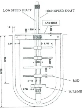
Figure 2.6 shows a coaxial mixer consisting of a pitched-blade turbine with wetting rods and a vessel wall-scraping anchor (Thibault et al., 2002; Tanguy et al., 2002). The rods can bring pre-dispersion at the liquid surface at the cost of remarkably low power. The primary consumption of
power in the coaxial mixer is from the high-speed inner impeller and the power number increases along with the speed ratio. The relationship between the speed ratio and threshold of transition regime is: the higher the speed ratio is, the lower the threshold is. The power constant KP of the
anchor depends on the speed ratio quadratically for the Newtonian fluid. For non-Newtonian fluid, the power constant varies along the parabolic curve while the increase of speed ratio, and decreases exponentially when the power law index increases.
Figure 2.6: Experimental setup. (Thibault et al., 2002)
Figure 2.7 shows the combinations of various impellers and an anchor (Foucault et al., 2004, 2005, and 2006). The power numbers of dispersion impellers were not affected by the anchor speed, while the anchor power consumption is affected by high-speed impellers. From the power curve of single impellers, it was noted that the critical Reynolds number from laminar regime to transition regime was 100 when single anchor was rotating, while this number changed into 20 with respect to the single Rushton turbine and the threshold for the turbulent regime was 1000. For the dispersion impellers, the laminar regime stopped at Re = 10, and the turbulent regime started from Re = 4500. In the coaxial mixer, however, the threshold for the transition regime decreases as the speed ratio rises when the system is under counter-rotating mode. In addition, this phenomenon does not happen in the co-rotating mode. The power consumption from anchor increases along with the Rushton turbine in counter-rotating mode and decreases in co-rotating
mode. This observation was explained as the addition and subtraction of different pressure forces imposed on the anchor.
Figure 2.7: Experimental system. (Foucault et al., 2004)
The flow pattern produced by a coaxial mixer is affected by the speed ratio between two impellers. Referring to the mixing time in this system, the mixing time increases along with the anchor speed before a certain speed, and then decreases as the anchor speed rises in counter-rotating mode. In co-counter-rotating mode, the mixing time decreases rapidly as the anchor speed rises. The co-rotating mode was more effective than the counter-rotating mode under the same power consumption (Espinosa-Solares et al., 2001). However, the ability of breaking segregation is stronger in counter-rotating mode. When the speed ratio is high, in the counter-rotating mode the mixing performance is more efficient (Bonnot et al., 2007), which is consistent with the numerical results obtained by Rivera et al. (2006).
The hydrodynamics of a co-rotating coaxial mixer with a combination of A200 impeller and an anchor was investigated by Rudolph et al. (2007). They agreed with the results obtained by Thebault and Tanguy (1997) and Köhler et al. (2003) about the effects of the speed ratio on the power consumption, and successfully drew the single master power curve for both Newtonian and Non-Newtonian fluids with modified Reynolds number.
A coaxial mixer that composed of a radial or an axial impeller mounted with an anchor was introduced by Farhat et al. (2007). It’s showed that the axial impeller-anchor system exhibited less power consumption and lower mixing time than that obtained by the combination of radial impeller and anchor.
To study and compare the hydrodynamics of the multi-shaft system instead of single impeller, a new universal correlation for characteristic rotational speed of the coaxial mixer (equation 2.1) was proposed by Farhat et al. (2008). Compared with the correlations proposed by Foucault et al. (2005) (equation 2.2), the new correlation can be used to obtain single power curve for different coaxial mixers regardless of the diameter difference of the inner impellers.
𝑁 =(!!!!!!!!!)
!!
(2.1)
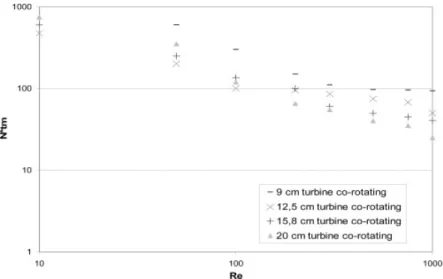
𝑁!"!!"#$#%&' = 𝑁! − 𝑁!; 𝑁!"#$%&'!!"#$#%&! = 𝑁! + 𝑁! (2.2) On the basis of the new correlation, the effects of diameters of inner impellers on the mixing time in a coaxial mixer composed of an anchor can be seen in Figure 2.8 (Farhat et al., 2008). Four Rushton turbines with different diameters (9, 12.5, 15.8, 20 cm) were used. The dimensionless mixing time of the Rushton turbine with 12.5 cm is the least in the range of laminar and early transition regime. Subsequently, the 20 cm Rushton turbine has the least mixing time. This observation was also found in the counter-rotating mode. While the Rushton turbine was working only, the 20 cm impeller, showed the smallest dimensionless mixing time due to its largest diameter in this investigation. The 9 cm Rushton turbine has the largest mixing time in any rotating mode. For a certain diameter, the co-rotating mode requires the least mixing time and counter-rotating the most in the laminar and early transition regime.
Figure 2.8: Influence of turbine diameter on the mixing time. (Farhat et al., 2008)
2.5 Superblend
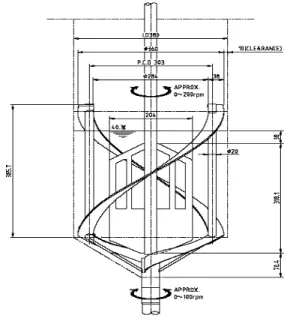
Due to the increasing application of highly viscous mixing, many new mixers are designed for satisfying the industrial requirement. Superblend coaxial mixer as shown in Figure 2.9 is a mixing instrument designed by SHI Mechanical & Equipment that characterized by a combination of a Maxblend impeller (generating high shearing and good circulation effects) and a helical ribbon (generating intensive shearing effect). This system has been proposed as a promising technology for viscous fluid mixing with large viscosity variation (Kuratsu et al., 1994; Farhat et al., 2009).
Using the correlation of the characteristic rotational speed proposed by Farhat et al. (2008), single power curve for Newtonian fluids can be obtained regardless the viscosity, speed ratio and rotating mode. When the speed ratio is above 10 in Superblend mixer, the co-rotating mode is more efficient than counter-rotating mode in the laminar and early transitional regimes. Although the Superblend mixer requires more power than some classical coaxial mixers (coaxial Rushton - Anchor mixer and coaxial Mixel TT - Anchor mixer), it exhibits higher mixing efficiency in terms of mixing time and mixing energy (Farhat et al., 2009).
Figure 2.9: Configuration of the Superblend mixer.
2.6 Solid-liquid mixing
2.6.1 Solid-liquid suspension
Generally, solid-liquid suspension is classified into three situations: on bottom motion, complete off-bottom suspension and uniform suspension as shown in Figure 2.10.
on-bottom motion complete Off-bottom suspension uniform suspension Figure 2.10: Different situations of suspension.
On-bottom motion suspension
This situation can be described as the complete motion of all the solid particles in the whole tank, regardless of the aggregations of particles nearby the bottom of the tank, which means there are still some particles are in the motion that has contact with the tank bottom. In this case, the surface area of particle cannot be totally calculated for the chemical reaction and transfer. It is suitable for dissolution of solids with high solubility.
Complete off-bottom suspension
This situation can be described as a complete motion of particles that no particle lays on the tank bottom for 1 s to 2 s, even though the suspension throughout the tank might not be uniform. Due to this whole motion, the surface area reaches the maximum level for the chemical reaction and a diversity of transfer. Since this situation is the minimum mixing requirement in the most solid-liquid systems, just suspended speed Njs is always chosen as an important parameter in the study
of solid-liquid system.
Uniform suspension
This situation can be described as the formation of both uniform particle concentration and particle size distribution in the whole tank.
Suspension percentage =!"# !"#$%# !"#$%& !"#$"#%&'" !" !"# !"#$%! !" !"# !"#$% !"#$!"# !"#$%& !"#$"%&'(" !" !"# !"#$%! !" !"#$%&'( !"#$ ×100% (2.3) here, the suspension percentage might greater, equal to or smaller than 100%. As for the uniform suspension, the suspension percentage is 100%. Basically, the particle distribution does not obviously improve if increasing the power input or rotating speed. This suspension is required in processes such as crystallization process and solid catalyzed reaction, where uniform solids concentration is vital to the efficiency of an operation unit or even the continuity of a whole production line. Of course, this ideal scene is based on more power input, more effective equipment configuration and certain operating conditions.
2.6.2 Distribution and dispersion in the solid-liquid mixing
Distribution and dispersion are discussed when the quality of solid-liquid mixing is studied. The uniform suspension depends both on good distribution and dispersion.
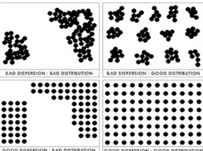
Figure 2.11: Difference between dispersion and distribution
The difference between distribution and dispersion can be observed in Figure 2.11. It can be seen that the appearance of aggregations in the first row. The difference of those conditions is the distribution of aggregations. In the first case, the particles aggregate randomly, while the aggregation distributes orderly in the second case. So the latter situation is called good distribution but bad dispersion.
In the first picture of the second row, we can see that there are still some aggregations from the macroscopic perspective. But for each aggregation, the distribution of particles is uniform. This is locally good dispersion but bad distribution in the whole container.
Finally when we notice the last picture, we can claim that this is exactly the ideal condition we expect in the solid-liquid system: no aggregation and uniform particle distribution everywhere in the tank, which is the uniform suspension. Therefore, both the distribution and dispersion of particles in the tank should be taken into account when the solid-liquid suspension is investigated.
2.6.3 Previous investigations on solid-liquid mixing
Referring to the solid-liquid suspension operation in industry, the most important concern is the specific power input and impeller speed needed to achieve the expected suspension states.
Taking just-suspended state as an example, it shows that when the agitation speed is greater than the just-suspended speed, the effect of agitation speed on the suspension degree is slight, while the power consumption increases dramatically. Thus, in order to get the expected effect without energy waste, the agitation speed should stay at approximately the just-suspended speed as this suspension state is required.
Since the critical impeller speed and power input for each suspension state has remarkable influence on the performance of the solid-liquid system, numerous studied on critical speed and power consumption have been carried out and published by researchers.
Oldshue (1983) pointed out that the achievement of the target suspension states lies on the agitation power input: more energy is required as the target state shifts from on-bottom suspension to off-bottom suspension and finally to uniform suspension (as shown in Table 2.1). Table 2.1: The influence of power input and operating conditions on the situation of solid-liquid suspension. (Oldshue, 1983)
The solid-liquid dispersion can be evaluated on the basis of power consumption evolution. A study on solid-liquid dispersion in a dual shaft Deflo - Paravisc mixer was carried out by Barar Pour et al. (2007) using power consumption evolution.
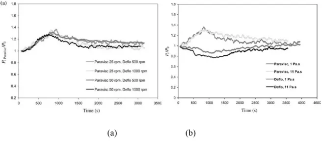
Figure 2.12: Power consumption evolution in solid-liquid dispersion. (Barar Pour et al., 2007) The evolution of power consumption in solid-liquid dispersion can be seen in Figure 2.12. Results showed that as the solids concentration increases, the power consumption of Paravisc increases; a short period after the incorporation of solid, there appears a peak for this trend. Then the power consumption goes down and forms a plateau eventually. This plateau can be explained as a symbol of achievement of final dispersion. On the contrary, the Deflo shows a minimum value where the maximum value appears for the Paravisc. It was concluded that the formation of agglomerates causes this power drop as the “shear-thinning” effect. The influence of agitation speed on the solid-liquid dispersion can be seen in Figure 2.13a. With the increasing of agitation speed for each impeller, the time takes to transfer to the plateau decreases and the influence of Paravisc on this is much more important than the Deflo. For the effect of continuous phrase viscosity on the solid-liquid dispersion as shown in Figure 2.13b, they revealed that the viscosity has no effect on the position of the power consumption peak. But there is a phenomenon that must be noted is the starting point of continuous phrase with higher viscosity is longer than dispersion media with lower viscosity.
(a) (b)
Figure 2.13: The influence of different factors on the solid-liquid dispersion: agitation speed; (b) continuous phrase viscosity. (Barar Pour et al., 2007)
Optical attenuation technique (OAT) is a non-intrusive technique to determine the solids
concentration in the solid-liquid dispersion process (Fajner et al., 1985). A light beam is emitted out of a light source and goes horizontally across the tank by avoiding the shaft and baffles, then get received by a light receiver. During this process, due to the presence of solid particles, the phenomenon of intensity attenuation is utilized as the detection of solids concentration on the whole horizontal plane. With several measurements on different elevations, the solids
concentration profile throughout the tank could be able to be obtained without any intrusion. Taking advantage of this technique, a few researchers (Pinelli et al., 2004; Fajner et al., 2008; Ochieng et al., 2006) have done several works on the solid-liquid dispersion field in terms of the effects of particle size, impeller speed and solids loading on solids concentration distribution, solid dispersion features and the like.
Although OAT has been proved that this technique is reliable and precise, it still has spacial limitation that makes it only able to offer the information on a single line, but not qualified to display the real details on the whole plane. To overcome this drawback, electrical resistance tomography (ERT) is currently applied in many application fields and regarded as the promising technology to measure and analyze the solids concentration in solid-liquid system. The primary
advantage of this technique is the realization of three-dimensional imaging in solid-liquid environment.
ERT is a tomographic system for the phrase concentration and velocity distributions measurement that characterized by non-invasive and soft-field. The principle of this measurement is according to Ohm’s law:
𝑉 = 𝑅𝐼 (2.4) where the voltage difference V [V] between pairs of adjacent electrodes mounted around the outside wall of aiming object is equal to the product of resistance R [Ω] and the electrical current I [A].
On the other hand, the resistance is inversely proportional to the electrical conductivity σ, [S/m]: 𝑅 = !! (2.5)
here K is a geometrical parameter, [1/m]. For ERT, K is related to the geometry of electrodes, the distance between them, and the diameter of the object. Since the electrical conductivity for each electrode pair can be obtained, image reconstruction algorithms then are used to compute a cross-sectional image. Finally, the tomogram of conductivity is able to display the situation of solids distribution as shown in Figure 2.14.
ERT measurement outperforms other tomograghic approaches on the faster data capture rate and finer spatial resolution (Williams and Beck, 1995). Numerous researcher have done a lot of works on the application of ERT in the study of solid-liquid system, liquid-liquid system, and gas-liquid system in pipe flow (Giguère et al. 2008, Stevenson et al. 2006, Norman et al. 2005), bubble columns(Vijayan et al. 2007, Jin et al. 2007) and LS riser (Razzak et al. 2009).
Reginald Mann (1997) pioneered in introduction this 3-D imaging technique for stirred tank and high anticipation was addressed for its innovative and promoting impact on the visualization of the mixing process inside the stirred tank.
Recently, ERT technique was utilized to investigate the homogeneous solids distribution in water in different geometries. Results proved that the degree of homogeneity in the mixer increases along with the impeller speed. When the homogeneity reaches a maximum degree, the further increase of the impeller speed is detrimental on the homogeneity (Hosseini et al., 2010; Tahvildarian et al., 2011; Harrison et al., 2012). Rather than being consistent throughout the tank, the axial and radial distributions of solids concentration are correlated to the operating conditions (Harrison et al., 2012). The diameter of impeller and the particle size have significant influence on the degree of homogeneity (Tahvildarian et al., 2011). Higher impeller speeds are required for larger particle (1.5 mm) to obtain homogeneous distribution compared to smaller particles (210 and 500 µm) (Hosseini et al., 2010).
2.7 Literature summary and contributions of this thesis
As reviewed above, the studies on the viscous mixing of both Newtonian and non-Newtonian fluids and solid-liquid system with a diversity of configurations have been widely published in open literature. However, there are still several problems that need to be noted and solved:
1. The working fluids might appear extremely high viscosity or cover a large range of viscosity, especially for the highly viscous non-Newtonian fluids used in food and polymerization industry. Single impeller or simple combination of impellers is unable to handle these complex cases. Therefore, a versatile mixer is strongly required in practical industry. The Superblend coaxial mixer is specifically designed for rheologically complex mixing
processes. In this thesis the investigation on the mixing performance in this mixer in both single-phase and multi-phase systems will provide a promising solution for the complex mixing task.
2. The definition of the characteristic rotational speed of the multi-shaft mixers has been a controversial research subject. In this thesis, to validate the applicability of a new correlation for characteristic rotational speed, the extensive investigation of the new correlation in more types of multi-shaft mixers was carried out.
3. The studies on the solid-liquid mixing are mostly confined to the complete off-bottom suspension level. In spite of the fact that some works have carried out on the uniform suspension, they merely used simple approaches such as correlation calculation, sampling measurement and simple optical approach to determine the solids concentration in the tank. In addition, water and low viscosity liquids have appeared as continuous phase in the uniform suspension in some works. However, in the mixing industry, solids distribution in the high viscosity liquids is more common and significant. In this thesis, to provide concrete and practical reference to industrial needs, the investigation of homogeneous solids distribution in viscous continuous phase in a coaxial mixer was first carried out by means of an advanced and reliable technique: electrical resistance tomography. In addition, quantitative measurement using this technique in solid-liquid system is introduced.
2.8 Objectives of the research
2.8.1 General objective
Characterization of mixing performance with high viscosity, shear-thinning fluids and solid-liquid distribution in Superblend mixer
2.8.2 Specific objectives
• Characterization of the mixing performance with highly viscous Newtonian in Superblend mixer in terms of power consumption and mixing time. One journal paper has been published after the accomplishment of this objective (Chapter 3).
• Analysis and comparison of mixing performance in multi-shaft mixers in terms of power consumption and mixing time. One journal paper has been published after the accomplishment of this objective (Chapter 4).
• Characterization of the mixing performance with Non-Newtonian fluids in Superblend mixer in terms of power consumption and mixing time. One journal paper has been submitted after the accomplishment of this objective (Chapter 5).
• Characterization of the hydrodynamics of homogeneous solid-liquid distribution in Newtonian continuous phrase in Superblend mixer in terms of homogeneous speed and mixing time. One journal paper has been submitted after the accomplishment of this objective (Chapter 6).
CHAPTER 3: ARTICLE 1: EFFECT OF OPERATING PARAMETERS ON
THE MIXING PERFORMANCE OF THE SUPERBLENDTM COAXIAL
MIXER
Article history: Submitted 4 April 2011, Accepted 8 September 2011, Published online 8 September 2011, Industrial & Engineering Chemistry Research.
Authors: Xiao Wang, Louis Fradette, Katsuhide Takenaka and Philippe A. Tanguy
3.1 Abstract
The mixing performance of a Superblend coaxial mixer, which combines a MaxblendTM impeller as the central impeller and a helical ribbon, was investigated experimentally in terms of power consumption and mixing time. The objective was to better understand the influence of the operating conditions on the mixing performance with Newtonian fluids. The experiment setup used allows each shaft to be driven independently. Taking advantage of individual torque-meter on each shaft and a well-developed decolorization technique, it was shown that the speed ratio RN
(NMaxblend / Nhelical ribbon = 1, 2, 4, 6, 8) and the rotating mode (up- and down-pumping of the helical
ribbon) have the largest influence on the mixing performance and that there is no universal operating mode for minimizing power and mixing time in all conditions or flow regimes. The results are presented in terms of the power consumption and mixing time throughout the laminar, transitional and turbulent regimes. The contribution of each impeller, the variation of flow patterns, the determination of the optimal operating conditions, and the comparison of power constant are discussed.
3.2 Introduction
Due to the demand for new processes able to handle extreme conditions of viscosity and rheological behaviors, fluid mixing remains an engineering challenge. Coaxial mixers have been designed to handle such difficult conditions. The fundament of the design is to take advantage of a wall-scraping impeller rotating at low speed (anchor or helical ribbon) to generate the bulk flow
and a high shear impeller (turbine of all kinds) rotating at higher speed to break and disperse the bulk.
Anchor blades and helical ribbons with wall-scraping effect have been commonly studied and used. Compared with anchor agitators that are limited in heat transfer application, helical ribbons have been widely used because of their ability to generate axial pumping with relatively low energy consumption. In order to achieve higher efficiency and avoid the drawbacks brought by conventional mixers such as stagnancy, segregation and cavern, coaxial mixers have been developed based on the empirical consideration.
In the literature, the combination of a Rushton turbine and a helical ribbon was proposed by Tanguy et al. Subsequently, this type of mixers was studied with different kinds of radial or axial impellers with an anchor or a helical ribbon. Generally, it is agreed that the power consumption of high-speed inner impeller is the most important consumption and is not affected by the low-speed outer impeller, while the latter is affected by the former. In the laminar regime, the product of Re times NP is constant and defined as power constant KP which is a critical parameter for the
power analysis. A clear relationship between power constant KP and speed ratio RN has also been
demonstrated. There is finally a relationship between the speed ratio and the threshold of the transitional regime: the higher the speed ratio is, the lower the thresholdbecomes.
Mixing time investigations in coaxial mixers with turbine and anchor showed that the co-rotating mode is more effective than counter-rotating mode due to its better axial circulation. However, the ability to break segregated regions with shear effect is weaker in the co-rotating mode than in the counter one. Some results showed that mixing time in the co-rotating mode will increase along with the speed ratio and for the counter-rotating mode the mixing performance is more efficient at high speed ratio.
In the 1990’s, a wide impeller named MaxblendTM was designed by SHI Mechanical & Equipment and showed excellent capabilities for operating in a wide range of fluid viscosities. The Maxblend mixer paddle is able to provide flow with axial circulation where the fluid goes upward at the tank wall and downward along the shaft. The results indicated that Maxblend has a uniform shear rate distribution compared with blade turbine impellers. In 2007, Louis Fradette et al. carried out a comprehensive investigation on the mixing characteristics of Maxblend and
confirmed that Maxblend impeller is very efficient for the mixing of viscous fluids based on short mixing time and low power consumption.
Recently, a new type of coaxial mixer named SuperblendTM has been proposed by SHI Mechanical & Equipment. It is formed from a combination of a Maxblend impeller and a helical ribbon. It has been proposed as a promising technology for viscous fluid mixing with large viscosity variation. In 2009, Farhat et al. firstly explored the power consumption and mixing time of Superblend using a new definition of rotational speed.
In this work, pushing further and deeper the investigation by Farhat et al., the objective is to quantify the effect of operating parameters (speed ratio and rotating mode) on the power consumption and mixing time of the Superblend mixer.
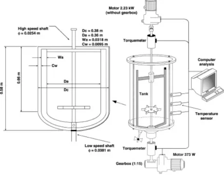
3.3 Experimental methods
Figure 3.1 shows the configuration of the Superblend (SB) studied in this work. It consists of an inner impeller (Maxblend, MB) and an outer impeller (helical ribbon, HR) driven with two separated motors. The diameter of MaxblendTM is Di = 0.2 m (Di / T = 0.53, T = 0.38 m) and the
specifics of the helical ribbon are shown in Table 3.1. The tank is a transparent cylinder with conical bottom. The liquid height is H = 0.44 m, and the liquid volume of the tank is approximately 40 L.
Table 3.1: Geometrical variables of the helical ribbon impeller
nb Do [m] Di / Do c / T p / Do L [m] w [m] h [m] Ds / T
2 0.36 0.56 0.08 1 0.54 0.03 0.38 0.07
where nb is the number of blades, Do the diameter of helical ribbon, c the clearance between the
ribbon and tank wall, T the tank diameter, p the pitch, L the blade length, w the blade width, h the height of helical ribbon, and Ds the shaft diameter.
A series of glucose-water solutions with different concentrations were prepared and used as Newtonian fluids. All the viscosity measurements were taken with a Bohlin Rheometer. Temperature of the tank is closely monitored because these solutions tend to change viscosity quickly with temperature.
The experiments were run at speed ratios of 1, 2, 4, 6, and 8. The two rotating modes (co- and counter-) were used at all ratios. Co-rotation corresponds to upward pumping of the helical ribbon at the wall while the counter-rotation sees the fluid going downward at the tank wall. The power consumption was determined by means of a torque meter mounted on the shaft of each impeller with a range of 0-20 N-m for the Maxblend and 0-100 N-m for the helical ribbon, respectively. Error on the torque measurement is 1% full scale, as per the manufacturer’s specification.
The corrected torque value Mc was calculated by subtracting the residual torque from each
measurement:
𝑀! = 𝑀!− 𝑀! (3.1)
where, Mm is the measured torque and Mr the residual torque, in N-m, respectively. Mr is
determined by measuring the torque at various speeds with the tank empty and the impellers on the shafts. It ranged from 0.3 - 0.6 N-m for the Maxblend and 0.1 - 0.5 N-m for the helical ribbon.
𝑃 = 𝑀!2𝜋𝑁 (3.2) Here, N is the rotational speed of the single impeller in s-1.
In coaxial mixers, the coexistence of two impellers results in the ambiguous definition of N. Previously, either outer impeller’s or inner impeller’s parameters was chosen as the characteristic parameters. Taking speed ratio and operating mode into account, Foucault et al. (2005) expressed the characteristic speeds as Nco-rotating = Ni - No and Ncounter-rotating = Ni + No. In addition, the inner
impeller’s diameter was used as the characteristic diameter due to the finding that the power number of the inner impeller is independent of the speed ratio. These new correlations allow the unique power curves to be obtained. However, this approach can only be applied when the speed ratio is above 10. Given that the speed ratios in this work are all below 10, a correlation proposed by Farhat et al. with its applicability for the Superblend was adopted as the characteristic speed in this paper.
𝑁′ =(!!!!!!!!!)
!! (3.3)
where, Ni and No are the rotational speeds of the inner impeller (Maxblend) and the outer
impeller (helical ribbon), respectively.
Therefore, the power number NP’, Reynolds number Re’ and power constant KP’ were expressed
based on equation (3.3) N!' =!!!'"! ! ! (3.4) 𝑅𝑒′ =!!′!!! ! (3.5) 𝐾!′= 𝑅𝑒′×𝑁!′ (3.6) Mixing time was measured by means of a decolorization method based on a fast acid-base
indicator reaction. 100 ml of pH indicator solution (0.08 wt % purple Bromocresol) is added to the fluid in the tank to visually differentiate between acidic (yellow, pH < 5.2) and alkaline (red, pH > 6.8) conditions. 10 ml of alkaline solution (NaOH) is poured into the tank and make the fluid appears red. At t = 0, 15 ml of acidic solution (HCl) is injected between the shaft and the wall on the liquid surface, while a video camera starts recording. A mixing evolution curve is
obtained after image analysis of the recording. From this curve, the mixing time is easily evaluated. In the present work, the time spent for reaching 95% of the complete decolorization state was chosen as the macro mixing time. This technique has been proven to be highly repeatable with low variability. No mixing time experiments are shown in the results for a speed ratio of 1 since these conditions only provided unmixed fluid and infinite mixing times.
3.4 Results and discussion
3.4.1 Overall Flow Pattern
The flow field being very complex in such a mixer, observation of the overall flow helps understand the mixing performance results. The flow field was observed by decolorization and tracer particles with density similar to the fluid (spray painted HDPE particles of 2 mm). Figure 3.2 respectively presents the flow field generated by each impeller alone (A), the expected flow field when both impellers are working (B), and the observed flow field from the experiments (C). The left side of Figure 3.2 A shows the flow field when the helical ribbon is pumping downward at the wall; the reverse direction simply generates the opposite flow field with all arrows reversed (typical operation of a helical ribbon). The right side of the same figure illustrates the flow field generally obtained with the Maxblend impeller showing a large circulation loop that is characteristic of this impeller.
Figure 3.2 B presents the expectations from the flow fields presented in Figure 3.2 A. On the left side of Figure 3.2 B, when impellers are in counter rotation i.e. when the helical ribbon is pumping downward, the expectations were so that the fluid would be going down along the shaft (Maxblend pumping) and the wall (helical ribbon pumping). Obviously, this requires a well balanced pumping between the two impellers so the fluid can go up in the gap between the two. The arrows indicate this expectation. On the right side of the same figure is represented the expectations for the co-rotation case i.e. when the helical ribbon is pumping upward at the wall. In this case, the collaboration of the two impellers is expected since both generate a flow that is very similar and should simply add to each other’s effect.
Figure 3.2 C presents the observed flow field from the experiments conducted in the lab with the helical ribbon pumping downward. The left side of the figure is obviously similar to Figure 3.2 A