HAL Id: hal-02561920
https://hal.archives-ouvertes.fr/hal-02561920
Submitted on 4 May 2020
HAL is a multi-disciplinary open access
archive for the deposit and dissemination of
sci-entific research documents, whether they are
pub-lished or not. The documents may come from
teaching and research institutions in France or
abroad, or from public or private research centers.
L’archive ouverte pluridisciplinaire HAL, est
destinée au dépôt et à la diffusion de documents
scientifiques de niveau recherche, publiés ou non,
émanant des établissements d’enseignement et de
recherche français ou étrangers, des laboratoires
publics ou privés.
Optimum for CO 2 transcritical power Rankine cycle
using exhaust gas from fishing boat diesel engines
E Autier, Afia Kouadri-Henni
To cite this version:
E Autier, Afia Kouadri-Henni. Optimum for CO 2 transcritical power Rankine cycle using exhaust gas
from fishing boat diesel engines. IFAC Workshop on Engine and Powertrain Control, Simulation and
Modeling, Nov 2009, Ruel-Malmaison, France. �10.3182/20091130-3-FR-4008.0011�. �hal-02561920�
Optimum for CO
2transcritical power Rankine cycle using exhaust gas from
fishing boat diesel engines
E. Autier*, A. Kouadri.**
*Avel Vor Technologies, INSA of RENNES (Tel: 0223238641; e-mail: e.autier@ avel-vor.fr). **INSA of RENNES, (e-mail: Afia.Kouadri-Henni@insa-rennes.fr)
Abstract: We present a study of a carbon dioxide transcritical power Rankine cycle using exhaust gas
from fishing boat diesel engine, in order to reduce fuel dependence. Two types of cycle have been studied: with or without internal heat exchanger. This work has been realised without defining the geometry of the heat exchangers. This choice means that their effectiveness is not considered.
Results show that an optimal pressure is found for each temperature below 438K for systems without internal heat exchanger and for each temperature below 503K for systems that have one. Moreover, results show that an optimal temperature exists for each pressure in systems with internal heat exchanger. Those facts prove that an optimisation of this system is possible at design of heat exchangers, and this, in correlation with all other parts: pump, expander, etc. Furthermore, presence of those optimal conditions shows us possibility of a future system control that enables to stay at optimum despite exhaust gas variations.
Keywords: energy dependence, optimum, economic systems, efficiency enhancement, optimal systems,
energy saving, exhaust gas.
1. INTRODUCTION
1.1 Introduction
Today, one of the most significant problems for all industrial domains is energy dependence. In fact, energy dependence is often synonymous of pollution and financial cost when fossil energies are used.
In France, fishermen are among the first victims of fuel price increase, as events of 2008 summer testified. Knowing that a trawler of medium size can consume more than 20 000 liters of fuel in two weeks, it is clear that each energy saving has to be studied and considered.
Schematically, between a quarter and a third of the energy contained in fossil combustible is rejected into exhaust gas, considering a marine diesel engine for fishing boats of medium size. Also, this rejected energy can be considered as a very interesting source for energy saving.
A part of this energy is besides already used into the turbocharger but heat is still available after it. That explains why a thermal cycle is considered here.
However, a choice has to be done with respect to the cycle and the working fluid. This choice depends on the efficiency of the cycle obtained but also on the environment and the safety of the installation. And it is the reason why carbon dioxide transcritical Rankine cycle was preferred to organic
Rankine cycle (ORC). In fact, the carbon dioxide is a natural gas with no ozone depleting potential (ODP) and a very low global warming potential (GWP) compare to many refrigerant which could be used as working fluid in ORC. This is also why a great work is being done today to study the use of carbon dioxide in automotive air-conditioning system.
1.2 State of the art
Many studies of transcritical Rankine power cycle can be found in literature. They prove the interest of this cycle, with respect to efficiency for low temperature heating source, and that even if we compare to ORC, which are known for their efficiency in this kind of case.
Chen Y. et al. 2006 presents a comparative study of a carbon dioxide transcritical power cycle compared to an organic Rankine cycle using R123 as working fluid, in waste heat recovery. The results show that comparable power output can be obtained. Besides, the SINTEF proposed in 2007 a rapid study of the integration of this technology on fishing boats, based on Chen work.
In a precedent study, Chen Y. et al. 2005 presents different cycles with carbon dioxide. For example, for power cycles, a carbon dioxide supercritical Brayton cycle was mentioned, but it works at a higher pressure than transcritical cycle, which is not an advantage. Moreover, the compressed fluid is not in a liquid phase in this case, which is not promising with respect to compactness and efficiency of compressor.
Carbon dioxide supercritical Brayton cycle was also studied for nuclear power plant, as the thesis of Dostal V. 2004, but the temperature which allows interesting results is higher is this case than in ours.
Furthermore, Zhang et al. 2005 and 2007 proposes theoretical and experimental investigation on solar transcritical Rankine cycle with very promising results. Even the experimental results are very hopeful, which proves the interest for that kind of cycle.
More recently, Cayer E. et al. 2008 presented a theoretical study of a carbon dioxide transcritical power cycle using a low temperature, with a source at 373K. This work shows that an optimum pressure, for a given temperature, can be found. This result is available for only one case. Also an analysis has to be done for different configurations in our case.
All those papers prove the interest of carbon dioxide transcritical cycle in low temperature source energy saving.
1.3 Work aim
In the enounced state of the art, no study is about the choice of optimal conditions for a given heating source and for no determined heat exchanger geometry. Also, the aim of our work presented here is to analyse the thermodynamic cycles before heat exchangers design, following the first law of thermodynamic, and that with a heat source of variable temperature. Moreover, a second law analysis is made using exergy tool. In fact, in function of the presence or not of working fluid optimal conditions with respect to the power output, design of heat exchangers will be affected, because of the searched temperature. In addition to that, control design of pump for real systems could be necessary - if optimum are found – because of variations of exhaust gas temperature and mass flow, but also because of fouling which can modify optimal conditions.
Also, this study is done for a not fixed geometry of heat exchanger, but for fixed sources only. Assumptions with respect to heat exchangers are explained in section 3.3. A presentation of thermal cycles considered is made before a recapitulation of assumptions. After that, results will be presented before being discussed.
2. CYCLE CONSIDERED
2.1 Transcritical Rankine cycle without internal heat exchanger
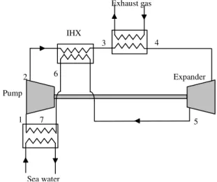
A transcritical Rankine cycle is a Rankine cycle with the particularity that the working fluid is at a pressure higher than its critical pressure at high pressure (HP) side and returns to a subcritical state after expansion and cooling. Figure 1 illustrates a schematic basic transcritical Rankine cycle in an entropic diagram and Fig. 2 illustrates a schematic system.
In this basic declination of transcritical Rankine cycle, four principal organs appear. States numbers refer to Fig. 1 and 2, and that for all this paper when cycle without internal heat exchanger is considered. States 6 and 7 in Fig. 1 will be defined in the following. The four transformations in each organ are:
- 1 to 2: Liquid compression from low pressure (LP) side to HP side.
- 2 to 4: Supercritical fluid heating, using exhaust gas heat. At state 4, temperature is higher than the critical one.
- 4 to 5: Expansion of supercritical fluid into the expander, from HP to LP.
- 5 to 1: cooling and condensation of the expanded fluid. Sea water is used here.
200 250 300 350 400 450 500 -2,5 -2,3 -2,1 -1,9 -1,7 -1,5 -1,3 -1,1 -0,9 -0,7 -0,5 Entropy (J/g.K) T e m p e ra tu re ( K )
Fig. 1. Transcritical Rankine cycle projected in a temperature-entropy diagram
Fig. 2. Schematic transcritical Rankine cycle without IHX using exhaust gas as heating source
For carbon dioxide, the critical properties selected are, following Span and Wagner 1996:
13 . 304 = c T K 38 . 7 = c P MPa
where Tc is the critical temperature of CO2 and Pc the critical
pressure of CO2. Also, temperature and pressure at state 4 1 2 4 5 7 Exhaust gas Sea water Pump Expander 1 2 4 5 3 6 7 2009 IFAC E-CoSM (E-CoSM'09)
Nov 30 - Dec 2, 2009, IFP, Rueil-Malmaison, France.
have to be higher than those values to have a transcritical Rankine cycle.
Several particularities exist in a transcritical cycle.
The first one is the temperature evolution during heat transfer with exhaust gas. In fact, the heat source temperature gliding is not a real problem in a counter flow exchanger with supercritical carbon dioxide as working fluid, because supercritical fluid will have a comparable gliding temperature as illustrated in Fig. 3. It is due to the absence of evaporation, which avoids a step of temperature for the working fluid side during the exchange. That important property allows a strong diminution of entropy creation during heating phase. Thus, the irreversibility creation is minimized.
Secondly, the temperature after expansion offers possibilities. As it can be seen on Fig. 1, the expansion is completely achieved before saturation. That means that the cavitations problem can be avoided in the expander, which is a very interesting property of this cycle. Furthermore, the temperature after expansion – at state 5 – allows the implantation of an internal heat exchanger (IHX). Knowing that possibility, both systems will be studied in this paper.
Fig. 3. Schematic temperature evolution during working fluid heating by exhaust gas
2.2 Transcritical Rankine cycle with internal heat exchanger
The addition of an IHX in a transcritical cycle allows saving energy which would be definitively lost otherwise.
In fact, if the temperature at state 5 is higher than at state 2, it is possible to use a part of the heat rejected during the cooling of the working fluid. This saving is represented by states 3 and 6. Figure 4 schematizes this type of cycle, the states numbers introduced here are linked with those of Fig. 1. In the rest of this paper, when IHX is introduced, states numbers referred to Fig. 1 and 4.
In the case of the systems studied here, HP side received energy from LP side into the IHX. Moreover, it is known that the mass flow is the same in each side of the IHX, because we work with a closed cycle. Also, assuming that the IHX is completely adiabatic, (1) can be written:
∫
=−∫
6 5 3 2 (1) . . . 2 2 T T T T pc CO ph CO C dT m C dT m& & where 2 COm& is mass flow of carbon dioxide in kg/s, Cpcis the cold fluid isobaric specific heat in kJ/(kg.K, Cphis the
hot fluid isobaric specific heat in kJ/(kg.K), and Ti is the
temperature at state i in K.
Fig. 4. Schematic transcritical Rankine cycle with IHX using exhaust gas as heating source
0 2 4 6 8 10 12 298 348 398 448 498 Temperature (K) Is o b a ri c s p e c if ic h e a t C p ( J /g .K ) 6,4MPa 8MPa 10MPa 13MPa
Fig. 5. Isobaric specific heat of carbon dioxide at different pressures as a function of temperature
Knowing the significant variations of isobaric specific heat in function of the temperature, as illustrated on Fig. 5, no consideration will be done about the effectiveness of the IHX, and also about other heat exchangers. Assumptions are presented in section 3.3.
3. SIMULATION HYPOTHESES
3.1 Hypotheses about exhaust gas
As mentioned in the introduction, this paper deals with a system which is studied for energy saving on fishing boats. In fact, very different types of engine and conditions of use are met on fishing boats.
0% Relative heat energy 100% Working fluid Exhaust gas Tout Tin T2 T4 1 2 3 4 5 6 7 Exhaust gas Sea water Pump Expander IHX
To compare equitably different configurations, the work was made using nominal, at full charge, data from Moteurs Baudouin, a French reference in marine engines, for a medium size engine of around 350kW. Those data are resumed in table 1. All those data are given for exhaust gas after turbocharger.
Table 1. Exhaust gas reference data
Rotation per minute (rot/min) Outlet Temperature (°C) Mass flow (kg/s) 1800 368 0.617
It can be noted that another source is available: the cooling system. This source contains an energy close to exhaust gas one. The choice of exhaust gas – authors excluding the use of both of them – is explained by exergy. In fact, exergy is the recoverable part of energy: a notion of quality of energy is introduced by this tool. Exergy recoverable in an exchanger can be expressed as:
− = ∆
∫
T T Q x E Outlet Inlet 0 1 & & δ (2)where∆E&xis the exergy recoverable, T the
temperature, Q&δ the heat transfer at T, and T0 the dead state temperature, equal here to 293 K. Power obtained corresponds to the power we could obtain if infinity of Carnot engines were used at each temperature T with a cold source at T0. Term − T T0
1 is called Carnot factor.
Thus, assuming that total heat areQ&cooler =393kW, kW
244 =
gas
Q& , temperatures are T0 = 293K, Tinlet,cooler =
353K, Tinlet, gas = 641K and specific heats are Cpcooler = 4.2
J/g.K, Cpgas = 1.2 J/g.K we find ∆E&xgas =80kw and
kw 35 = ∆ cooler x
E& . Those results proof the great interest of
exhaust gas compared to cooler.
3.2 CO2 thermodynamic properties
Used CO2 thermodynamic properties are calculated by the
fundamental equation of state developed by Span and Wagner. Their paper is the reference for subcritical and supercritical carbon dioxide properties, using the Helmholtz free energy equation and a lot of selected experimental data. In our work, those equations are integrated into a Scilab file and all the calculation protocol results from them.
3.3 Internal and external exchangers
The work presented here is a pre-design work. In fact, the purpose is to find the best conditions in terms of pressure and temperature at state 4, and that as a function of the heating source.
Also, the only hypothesis assumed with respect to heat exchangers here is that a minimum temperature difference of 5 K is obtained at the pinch point, to assure an exchange. Thus, no effectiveness is considered and no geometry hypotheses are made.
That means that exhaust gas side pressure losses, system compactness, and all exchanger physical properties are neglected.
3.4 Neglected losses
The losses due to pressure drop and thermal insulation have been neglected. Only the losses due to efficiencies of pump and turbine, and thermal gradient in exchangers are considered.
3.5 Pump and expander efficiency
Pump efficiency is taken equal to 0.8 and expander efficiency is 0.7, as it can be found in literature as in Chen et al. 2005. The interpretation of those efficiencies is:
(
)
(
)
(
)
/(
)
(3b) (3a) / , 5 4 5 4 exp 1 2 1 , 2 is is pump h h h h h h h h − − = − − = η ηwhere hi is the enthalpy in J/g at state i, hi,is is the enthalpy at
state i if the previous transformation was isentropic, so without loss, in J/g, ηpump and ηexare respectively the
efficiency of pump and expander.
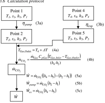
3.6 Calculation protocol
Fig. 6. Schematic protocol of calculation with equations for system without IHX
The energy analysis is based on the first law of thermodynamic. Parameters which have to be taken into consideration are the following:
(
)
(4b) ) ( (4a) 2 4 , , 4 Oulet Gas, 2 -h h T T C m m ∆T T T Outlet Gas Inlet Gas pGas Gas CO − = + = & & Point 1 T1, s1, h1, P1 Point 4 T4, s4, h4, P4 (3a) pump η (3b) expη
Point 2 T2, s2, h2, P2 Point 5 T5, s5, h5, P5 2 CO m&(
) (
)
(
)
(
)
(
)
(5c) (5b) (5a) 5 4 1 2 1 2 5 4 2 2 2 h h m W h h m W h h h h m W CO ex CO pump CO − = − = − − − = & & & & & & W&2009 IFAC E-CoSM (E-CoSM'09)
Nov 30 - Dec 2, 2009, IFP, Rueil-Malmaison, France.
- high pressure HP=P2=P3=P4. Pressure range for HP is
8 to 20 MPa.
- gas inlet temperature is 623K, isobaric specific heat is assumed at Cp,Gas = 1.2J/g.K and mass flow is
617
.
0
=
Gasm
&
kg/s.- temperature at state 4 T4. Temperature range for T4 is
373 to 618K.
- efficiencies of pump and expander respectively 8 . 0 = pump η and 0.7 exp= η
- minimum temperature difference into heat exchangers at pinch point∆T=5K
- cold temperature, at state 1 and 7 which gives also LP, because of saturation. This temperature is assumed to be equal to 298K, which is equivalent in sea water at 293K with∆T =5K at the pinch point. The equivalent
pressure is 6.4MPa.
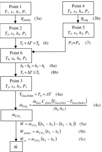
Fig. 7. Schematic protocol of calculation with equations for system with IHX
With those values, equations used are resumed in Fig. 6 for system without IHX and in Fig. 7 for system with IHX. In each state of the carbon dioxide, only two of the four parameters Ti, si, hi and Pi are necessary to determine the two
other. Carbon dioxide mass flow is obtained by energy conservation between heat delivered by exhaust gas and heat recovered by carbon dioxide.
4. RESULTS AND DISCUSSION
4.1 Power output analysis for cycle without IHX
Figures 8 and 9 show power output available, assuming conditions and hypotheses enunciated previously, with a cycle without IHX.
Two principal observations can be extracted from those graphs.
Firstly, it can be seen that under a high temperature of around 438K here, and for the selected high pressure range, an optimal pressure can be found, optimising the power output. This pressure is clearly depending on high temperature available.
Secondly, in the selected range of pressure, if temperature higher that 438K is available, then the maximal pressure possible will be searched, if efficiencies of pump and expander are fixed.
In fact, it appears that the higher the pressure is, the higher the available power output is, if pressure is lower than 20MPa and temperature higher than 438K.
373 ,15 423,15 473,15 523 ,15 573 ,15 8 10 12 14 16 18 20 0 5 10 15 20 25 30 Power Output (kW) Temperature (K) Pressure (MPa)
Fig. 8. Power output without IHX as a function of HP and T4.
0 5 10 15 20 25 30 373,15 423,15 473,15 523,15 573,15 623,15 673,15 Temperature T4 (K) P o w e r O u tp u t (k W ) 8 MPa 13 MPa 20 MPa
Fig. 9. Power output without IHX as a function of T4 for HP = 8 MPa, 13 MPa and 20 MPa.
Thus, those results show that systems without IHX present an optimal pressure – over the studied range – for Point 1 T1, s1, h1, P1 Point 4 T4, s4, h4, P4 (3a) pump η (3b) exp
η
Point 2 T2, s2, h2, P2 Point 5 T5, s5, h5, P5 Point 6 T6, s6, h6, P6 (6) 6 2 T T T +∆ = P5=P6 (7) (8b) (8a) 5 3 2 3 6 5 T T T h h h h ≤ ∆ + − = − Point 3 T3, s3, h3, P3(
)
(4c) (4a) 3 4 , , 4 Oulet Gas, 2 (h -h ) T T C m m ∆T T T Outlet Gas Inlet Gas pGas Gas CO − = + = & & 2 CO m& W&(
)
(
)
(
)
(
)
(
)
(5c) (5b) (5a) 5 4 1 2 1 2 5 4 2 2 2 h h m W h h m W h h h h m W CO ex CO pump CO − = − = − − − = & & & & & &temperatures lower than 438K, whereas for high temperatures, the power output increase with pressure.
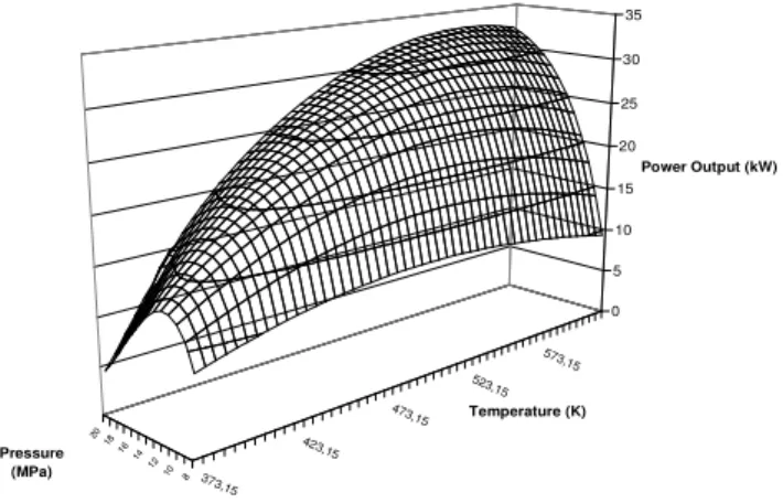
4.2 Power output analysis for cycle with IHX
Figures 10 and 11 point out the results obtained for the system with IHX. Also, it can be seen that the maximal power output available is higher on system with IHX than without, for a same high temperature.
373,15 423,15 473,15 523,15 573,15 8 10 12 14 16 18 20 0 5 10 15 20 25 30 35 Power Output (kW) Temperature (K) Pressure (MPa)
Fig. 10. Power output with IHX as a function of HP and T4.
Moreover, Fig. 10 shows that an optimal temperature exists for each pressure over the studied range and that an optimal pressure also exists for each temperature between 373K and 503K.
And in fact, contrary to the system without IHX, an optimal temperature exists for each pressure over the range studied here. Figure 11 points out this optimum temperature and its variation as a function of the high pressure.
Figure 12, extracted from Fig. 10, confirm the presence of an optimal pressure for temperature lower than 503K.
Those results show that systems with IHX and under the assumed conditions, present an optimal temperature for each pressure studied here but also an optimal pressure for low temperatures of our range.
0 5 10 15 20 25 30 35 373,15 423,15 473,15 523,15 573,15 623,15 673,15 Temperature T4 (K) P o w e r O u tp u t (k W ) 8 MPa 13 MPa 20 MPa
Fig. 11. Power output with IHX as a function of T4 for HP = 8 MPa, 13 MPa and 20 MPa.
0 5 10 15 20 25 30 35 8 10 12 14 16 18 20 22 Pressure (MPa) P o w e r O u tp u t (k W ) 403,15 503,15 603,15
Fig. 12. Power output with IHX as a function of HP for T4= 403K, 503K and 603K
4.3 Exergetic analysis
We can distinguish two types of exergetic efficiency, define in (9) and (10). gas System Ex x E W & & ∆ = , η (9) Exchanger CO Cycle Ex x E W , , 2 & & ∆ = η (10) with:
(
)
(
0)
(11) , 22Exchanger CO outlet inlet outlet inlet
CO m h h T s s
x
E = − − −
∆& &
W& is the useful work in kW, ∆E&xgas has been defined in (2), Exchanger CO x E , 2 &
∆ the CO2 exergy variation throw the principal heat exchanger in kW, houtlet and hinletCO2 enthalpies
respectively at the outlet and the inlet of principal heat exchanger in kJ/kg, soutletand sinletCO2 entropies
respectively at the outlet and the inlet of principal heat exchanger in kJ/kg.K.
Equation (10) implies that optimisation of ηEx ,Cycledoes not
correspond to maximise power output.
We find maximal ηEx ,Cycle, for system with IHX, when both temperature and pressure are the highest as possible. In our case, a value about 53% is obtained.
For cycles without IHX, maximal ηEx ,Cycle is about 43% for temperature between 450K and 470K, and pressure between 18MPa and 20MPa.
This difference can be explained by the exergy recovered into the IHX.
ConcerningηEx,System, maximal values are obtained for the
same conditions than maximal power output. Those values – with our assumptions – are about 32% for systems without IHX and about 41% for systems with IHX.
2009 IFAC E-CoSM (E-CoSM'09)
Nov 30 - Dec 2, 2009, IFP, Rueil-Malmaison, France.
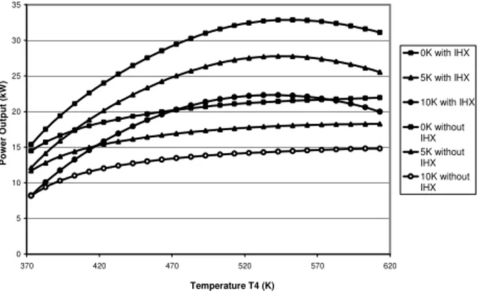
4.4 Influence of the temperature difference at the pinch point
One of our strong assumptions is the temperature difference at pinch point. We have imposed 5K and all previous results have been obtained with this assumption. A comparison for different pinch points has been done. Results are shown on Fig. 13 and 14, respectively representing power output as a function of T4 at HP=13MPa and as a function of HP at T4
=403K. This temperature has been chosen because each system has an optimal HP for this value, following previous results. 0 5 10 15 20 25 30 35 370 420 470 520 570 620 Temperature T4 (K) P o w e r O u tp u t (k W ) 0K with IHX 5K with IHX 10K with IHX 0K without IHX 5K without IHX 10K without IHX
Fig.13. Power output as a function of temperature T4 for 0K, 5K and 10K of temperature difference at pinch point, HP=13MPa.
The results show that this assumption has a significant impact on power output, on optimal temperature for an imposed HP and on optimal pressure for an imposed T4. It
proves that to optimise a system, good design of heat exchangers is very important. We also can suppose that, knowing problem of fouling with diesel engine exhaust gas, a real system should be controlled by an auto-adaptive controller. 0 5 10 15 20 25 10 11 12 13 14 15 16 17 18 19 20 Pressure (MPa) P o w e r o u tp u t (k W ) 0K with IHX 5K with IHX 10K with IHX 0K without IHX 5K without IHX 10K without IHX
Fig.14. Power output as a function of HP for 0K, 5K and 10K of temperature difference at pinch point, T4=403K.
4.5 Discussion
Principal results of our study show that an optimal pressure exists for temperatures lower than 438K in systems without IHX and lower than 503K for systems with it. Moreover, an optimal temperature exists for each pressure of the studied range, but only for systems with IHX.
Optimal pressure obtained for low temperature can be compared to the study of Cayer E. et al. In fact, in their study, the carbon dioxide temperature at state 4 is fixed at 368K, and at states 1 and 7 of 288K. The closest case present in our work is a temperature of 373K at state 4 and a temperature at states 1 and 7 of 298K. Nevertheless, it must be noticed that assumptions are not the same, and that implies significant differences.
Cayer E. et al. finds an optimal pressure, with respect to power output, at 11.5MPa, with or without IHX. This result is close to those of our work with an optimal pressure of 13.3MPa without IHX and of 11.8 MPa with it. However, we can also observe that Cayer E. et al. finds maximum efficiency at a pressure of 13.6MPa for system without IHX and at a pressure of 11.3MPa with it. Those values are very close of ours, and corroborate well our work.
For higher temperatures, the power output increases with pressure. But it must be remembered that our study range stops at 20MPa. Also, it is possible that an optimal pressure exists also at temperatures higher than values cited before, but this pressure would be above 20MPa, which would present technological problems for pump as for the expander.
To understand the presence of an optimal temperature in systems with IHX, hypotheses and equations have to be well observed. In fact, in (5a), equation which is common to systems with or without IHX, it can be seen that the power output is the result of a multiplication between carbon dioxide mass flow and the enthalpy variation∆hwork:
(
) (
)
(
)
work h h h h h − − − =∆ 1 2 5 4 (12)where (h4-h5) is representative of the enthalpy variation into
the expander and (h2-h1) is representative of the enthalpy
variation into the pump. Equation (12) is representative of the useful energy per mass of working fluid. At each pressure, (h2-h1) is constant with respect to temperature at
state 4, assuming same pump efficiency and same cold temperature, but (h4-h5) varies following the high
temperature. Fig. 13 shows the evolution of the useful energy per mass, for a HP of 13MPa and the evolution of carbon dioxide mass flow with or without IHX, as a function of the temperature at state 4.
0 5 10 15 20 25 30 35 40 45 373,15 423,15 473,15 523,15 573,15 623,15 Temperature (K) U s e fu l e n e rg y p e r m a s s ( k J /k g ) 0 0,2 0,4 0,6 0,8 1 1,2 1,4 C a rb o n d io x id e m a s s f lo w ( k g /s ) Enthalpy variation (kJ/kg) Carbon Dioxide mass flow for system with IHX (kg/s) Carbon Dioxide mass flow for system without IHX (kg/s)
Fig. 15. Useful energy per mass and carbon dioxide mass flow vs. T4, HP = 13 MPa.
The evolution of mass flow is totally different following the presence or not of an IHX. In fact, the use of an IHX allows a slower decrease of carbon dioxide mass flow and that is why an optimal temperature appears with IHX and not without. But that also means that if the assumption that 5K of temperature difference is obtained in each case at the pinch point is not respected, the presence of that optimum can disappear or glide to another value. In a future work, this problem will be studied.
5. CONCLUSION
Finally, transcritical power Rankine cycles using exhaust gas as heating source present different optimal conditions, with respect to the first law of thermodynamic. In fact, systems without IHX present only an optimal pressure for temperatures lower than 438K, and under the assumptions, whereas systems with IHX present both an optimal pressure for temperatures lower than 503K and an optimal temperature for each pressure.
Those results are only available in the studied ranges of temperature and pressure. Moreover, assumptions about heat exchangers, but also all parts of the system, have a significant impact on those results, and we can understand this by looking at the influence of temperature and of carbon dioxide mass flow.
This study points out the importance of the heat exchangers design to obtain a target temperature at nominal conditions. It also shows that the temperature difference at the pinch point has a significant impact. This observation implies the necessity of having an auto-adaptive control.
Regarding those results, the next step of our work will be to propose a control of the cycle pump in function of heating source fluctuations, and that for fixed heat exchangers.
REFERENCES
Boewe, D.E., Bullard, C.W., Yin, J.M. and Hrnjak, P.S. (2001). Contribution of internal heat exchanger in transcritical R744 cycle performance. International
journal of heating ventilation air conditioning and refrigerating research, volume 7 (2), 155-168.
Cayer, E., Galanis, N., Desilets, M., Nesreddine, H., Roy, P. (2009). Analysis of a carbon dioxide transcritical power cycle using low temperature source. Applied Energy, volume 86 (7-8), 1055-1063.
Chen, Y., Lundqvist, P., and Platell, P. (2005). Theoretical research of carbon dioxide power cycle application in automobile industry to reduce vehicle's fuel consumption. Applied Thermal Engineering, volume 25, 2041-2053.
Chen, Y., Lundqvist, P.,Johansson, A. and Platell, P. (2006). A comparative study of the carbon dioxide transcritical power cycle compared with an organic Rankine cycle with R123 as working fluid in waste heat recovery.
Applied Thermal Engineering, volume 26 (17-18),
2041-2053.
Dostal, V. (2004). A supercritical carbon dioxide cycle for next generation nuclear reactors. Doctoral thesis defence
presentation, Department of nuclear engineering, MIT.
Fartaj, A., Ting, D.S.-K. and Yang, W. W. (2004). Second law analysis of the transcritical CO2 refrigeration cycle.
Energy and conversion management, volume 45, 2269 –
2281.
Ladam, Y. and Skaugen, G. (2007). CO2 as working fluid in a
Rankine cycle for electricity production from waste heat sources on fishing boats. Summary Report. Sintef
technical report.
Span, R. and Wagner, W. (1996). A new equation of state for carbon dioxide covering the fluid region from the triple-point temperature to 1100K et pressures up to 800 MPa.
Journal of physical and chemical reference data, volume
25 (6), 1513-1596.
Zhang, X.R., Yamaguchi, H., Fujima, K., Enomoto, M., Sawada, N. (2005). A feasibility study of CO2-based Rankine cycle powered by solar energy. JSME
International Journal, volume 43 (3), 540-547.
Zhang, X.R., Yamaguchi, H., Fujima, K., Enomoto, M., Sawada, N. (2007). Theoretical analysis of a thermodynamic cycle for power and heat production using supercritical carbon dioxide. Energy, volume 32, 591-599.
2009 IFAC E-CoSM (E-CoSM'09)
Nov 30 - Dec 2, 2009, IFP, Rueil-Malmaison, France.