UNIVERSITÉ DE MONTRÉAL
DESIGN AND DEVELOPMENT OF A LIGHTWEIGHT ANKLE EXOSKELETON FOR HUMAN WALKING AUGMENTATION
YACINE BOUGRINAT
DÉPARTEMENT DE GÉNIE MÉCANIQUE ÉCOLE POLYTECHNIQUE DE MONTRÉAL
MÉMOIRE PRÉSENTÉ EN VUE DE L’OBTENTION DU DIPLÔME DE MAÎTRISE ÈS SCIENCES APPLIQUÉES
(GÉNIE MÉCANIQUE) AVRIL 2018
UNIVERSITÉ DE MONTRÉAL
ÉCOLE POLYTECHNIQUE DE MONTRÉAL
Ce mémoire intitulé :
DESIGN AND DEVELOPMENT OF A LIGHTWEIGHT ANKLE EXOSKELETON FOR HUMAN WALKING AUGMENTATION
présenté par : BOUGRINAT Yacine
en vue de l’obtention du diplôme de : Maîtrise ès sciences appliquées a été dûment accepté par le jury d’examen constitué de :
M. STIKOV Nikola, Ph. D., président
M. ACHICHE Sofiane, Ph. D., membre et directeur de recherche M. RAISON Maxime, Doctorat, membre et codirecteur de recherche M. LAMOUREUX Étienne, B.Ing., membre
ACKNOWLEDGEMENTS
Any achievement, particularly in studies and research, is not only the result of our work but also the result of the support of many outstanding persons. In this regard, I would like to heartily thank my supervisors Professor Sofiane Achiche and Professor Maxime Raison who have been supportive during all my master studies. I would like to thank you for giving me the opportunity to work on such an interesting project which helped me develop different and many new skills. Thank you for inspiring me and pushing me to my limits. Thank you for all the support you have provided during my studies which was very important to successfully finish this amazing project. Apart from research, I am grateful to you for giving me the opportunity to have a remarkable teaching experience that has significantly enriched my experience at Polytechnique Montreal.
I also would like to thank Alvaro Ramirez who helped me in many occasions to find solutions to technical issues that I faced during the project. Alvaro has shared lots of his experience with me which was very helpful in pushing the project forward. Thank you, Alvaro.
Thank you, all the members of our research lab, (Conception de Systèmes Intelligents et Mécatroniques - COSIM) for making our workplace environment, friendly and collaborative. Finally, I would like to express my profound gratitude towards my parents and family members who have been very supportive and encouraging during all my studies.
RESUMÉ
La plupart des exosquelettes motorisés de la cheville ont une masse distale considérable, ce qui limite leur capacité à réduire l’énergie dépensée par l’utilisateur durant la marche. L’objectif de notre travail est de développer un exosquelette de chevilles avec le minimum de masse distale ajoutée comparé aux exosquelettes motorisés de chevilles existants. Aussi, l’exosquelette doit fournir au moins 50 Nm de support au couple de flexion plantaire. L’exosquelette développé dans le cadre de ce mémoire utilise deux câbles Bowden pour transmettre la force mécanique de l’unité d’actionnement attachée à la taille aux deux tiges en fibre de Carbonne attachées à la botte de l’utilisateur. Quand les deux tiges sont tirées, ils génèrent un couple qui supporte le mouvement de flexion plantaire à la fin de la phase d’appui du cycle de marche. Une pièce conçue sur mesure et imprimé en plastique par prototypage rapide a été attachée au tibia pour ajuster la direction des câbles. Une étude d’optimisation a été effectuée pour minimiser la masse des tiges limitant ainsi la masse distale de l’exosquelette (attaché au tibia et pied) à seulement 348 g. Le résultat principal obtenu à partir des tests de marche est la réduction de l’activité des muscles soléaire et gastrocnémien du sujet par une moyenne de 37% et 44% respectivement lors de la marche avec l’exosquelette comparée à la marche normale. Cette réduction s’est produite quand l’exosquelette a fourni une puissance mécanique de 19 ± 2 W avec un actionnement qui a commencé à 38% du cycle de marche. Ce résultat démontre le potentiel de notre exosquelette à réduire le cout métabolique de marche et souligne l’importance de réduire la masse distale d’un exosquelette de marche.
ABSTRACT
Most of powered ankle exoskeletons add considerable distal mass to the user which limits their capacity to reduce the metabolic energy of walking. The objective of the work presented in this master thesis is to develop an ankle exoskeleton with a minimum added distal mass compared to existing autonomous powered ankle exoskeletons, while providing at least 50 Nm of assistive plantar flexion torque. The exoskeleton developed in this master thesis uses Bowden cables to transmit the mechanical force from the actuation unit attached to the waist to the carbon fiber struts fixed on the boot. As the struts are pulled, they create an assistive ankle plantar flexion torque. A 3D-printed brace was attached to the shin to adjust the direction of the cables. A design optimization study was performed to minimize the mass of the struts, thereby limiting the total added distal mass, attached to the shin and foot, to only 348 g. The main result obtained from walking tests was the reduction of the soleus and gastrocnemius muscles activity by an average of 37% and 44% respectively when walking with the exoskeleton compared to normal walking. This reduction occurred when the exoskeleton delivered a mechanical power of 19 ± 2 W with an actuation onset fixed at 38% of the gait cycle. This result shows the potential of the proposed exoskeleton to reduce the metabolic cost of walking and emphasizes the importance of minimizing the distal mass of ankle exoskeletons.
TABLE OF CONTENTS
ACKNOWLEDGEMENTS ... III RESUMÉ ... IV ABSTRACT ... V TABLE OF CONTENTS ... VI LIST OF TABLES ... IX LIST OF FIGURES ... X LIST OF SYMBOLS AND ABBREVIATIONS... XIII LIST OF APPENDICES ... XIVCHAPTER 1 INTRODUCTION ... 1
CHAPTER 2 LITERATURE REVIEW ... 3
2.1 Human Walking Biomechanics ... 3
2.1.1 Gait Cycle Phases ... 3
2.1.2 Joints Kinematics and Dynamics ... 4
2.1.3 Metabolic Cost of Walking ... 6
2.2 Lower Limb Exoskeletons ... 7
2.2.1 Definition of an Exoskeleton ... 7
2.2.2 Classification of Exoskeletons ... 7
2.2.3 Trends in the Design of Walking Augmentation Exoskeletons ... 11
2.2.4 Ankle Exoskeletons for Reducing Metabolic Cost of Walking ... 19
2.2.5 Design Challenges ... 24
CHAPTER 3 RATIONAL OF THE PROJECT ... 27
3.1 Summary of the Problem ... 27
3.3 Specific Objectives ... 27
CHAPTER 4 ARTICLE 1: DESIGN AND DEVELOPMENT OF A LIGHTWEIGHT ANKLE EXOSKELETON FOR HUMAN WALKING AUGMENTATION... 29
4.1 Introduction ... 30
4.2 System Overview ... 32
4.3 Mechanical Design ... 34
4.3.1 Augmentation Principle ... 34
4.3.2 Design Criteria ... 34
4.3.3 Main Design Components and their Selection ... 35
4.3.4 Struts Optimization ... 38
4.4 Control System and Electronics ... 50
4.5 Experimental Tests ... 51
4.5.1 Mechanical Efficiency ... 52
4.5.2 Human Walking Trials ... 52
4.6 Results and Discussion ... 54
4.6.1 Exoskeleton Mass ... 54
4.6.2 Human Walking Trials ... 55
4.7 Conclusion ... 61
CHAPTER 5 ADDITIONAL DETAILS ON METHODS AND RESULTS ... 68
5.1 Summary of the Accomplished Work ... 68
5.2 Control System ... 69
5.3 Graphical User Interface ... 71
5.4 Mechanical Test ... 72
5.5 Human Walking Tests ... 73
5.5.2 Data Processing ... 74
CHAPTER 6 GENERAL DISCUSSION ... 75
6.1 Summary of the Article’s Discussion ... 75
6.2 Limits and Perspectives of the Project ... 76
6.2.1 Mechanical Design ... 76
6.2.2 Control System ... 77
6.2.3 Exoskeleton Evaluation ... 78
CHAPTER 7 CONCLUSION AND RECOMMENDATIONS ... 79
BIBLIOGRAPHY ... 80
LIST OF TABLES
Table 2-1: Actuation systems ... 16
Table 4-1: Mass of selected active ankle exoskeletons ... 35
Table 4-2: Design variables ... 39
Table 4-3: Design parameters ... 39
Table 4-4: Numerical values for parameters ... 45
Table 4-5: Obtained results ... 45
Table 4-6: Human walking trials performed for the exoskeleton evaluation ... 53
LIST OF FIGURES
Figure 2-1: Gait cycle phases. Copyright © 2008 IEEE [15] ... 3
Figure 2-2: Anatomical body planes. Sagittal (red), median (green), and coronal (blue) [27] ... 4
Figure 2-3: Lower limb movements in the sagittal plane ... 4
Figure 2-4: Joint angles over the gait cycle ... 5
Figure 2-5: Joint torques over the gait cycle ... 5
Figure 2-6: Joints power over the gait cycle ... 6
Figure 2-7: HAL-5 Exoskeleton (left) © Nilsson et al.; licensee BioMed Central Ltd. 2014 [48], H2 Exoskeleton © Bortole et al. 2015 [49], Ekso Bionics Exoskeleton Copyright © IEEE 2012 [50] ... 8
Figure 2-8: The FORTIS exoskeleton [62] ... 9
Figure 2-9: Pneumatic artificial muscle used in an ankle exoskeleton [85] ... 13
Figure 2-10: Schematic of a SEA ... 14
Figure 2-11: SEA used in a walking robot. Copyright © IEEE 1999 [100] ... 14
Figure 2-12: Harmonic drive. Copyright © IEEE 2017. [108] ... 15
Figure 2-13: Harvard Wyss institute exosuit. © Panizzolo et al. 2016 [13] ... 18
Figure 2-14: (A) a schematic of the unpowered exoskeleton developed by Collins et al. (B) the mechanical clutch [1] ... 20
Figure 2-15: The Achilles exoskeleton. Copyright © IEEE 2016 [98] ... 22
Figure 2-16: (A) Alpha exoskeleton (B) Beta exoskeletons. Copyright © IEEE 2015 [21] ... 23
Figure 2-17: Mooney et al. exoskeleton. © Mooney and Herr. 2016 [118] ... 24
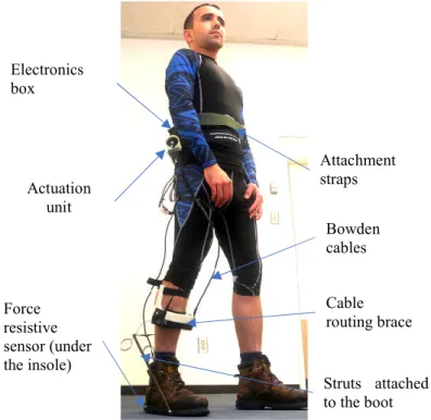
Figure 4-1: Overview of the WAXO exoskeleton. The actuation unit was attached to the waist using straps. Bowden cables were used to transmit the force to the ankle by pulling a struts structure attached to the boot. A 3d-printed brace attached to the shin changed the direction of the cables to pull the struts. An FSR inserted under the insole was used to detect heel strikes. The electronic components were enclosed in a plastic box attached to the waist ... 33
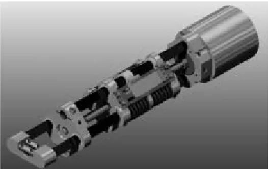
Figure 4-2: WAXO actuation unit. The actuation unit include a geared brushless DC motor and a pulley that guides two Bowden cables ... 36 Figure 4-3: (A) The cable routing brace attached to the shin was used to change the direction of the
cables (B) a zoomed figure of the cable routing brace ... 37 Figure 4-4: Layout of the struts on the foot. (a) configuration of the struts assembly when the foot
is on the ground (b) Configuration of the struts assembly when the foot is on maximum plantarflexion during walking ... 40 Figure 4-5: Objective function and isocontours of the constraints. The constraints “distance to
shank” (red), “cable brace height” (green) and “Max. strut length” (yellow) are active. Changing those constraints will change the solution ... 46 Figure 4-6: Effect of the maximum strut length parameter on the maximum lever arm. In this case,
the maximum strut length varied, while the maximum height is fixed at 300 mm ... 47 Figure 4-7: Effect of the maximum brace height parameter on the maximum lever arm. In this case,
the maximum brace height parameter is varied, while the strut length is fixed to 360 mm in this case ... 48 Figure 4-8: (A) The design variables for the mass optimization problem were the thickness, t[mm]
and the width, w[mm] of the struts (B) The struts were fixed on the points O and F. A force of 200 N was applied at the point C at an 11° angle with the horizontal ... 49 Figure 4-9: Control system architecture. The control system includes an FSR sensor that detects
the heel strike. An mbed lpc1864 microcontroller calculates the average gait cycle period, then sends a signal to the PC software at the actuation timing. The PC software sends the desired torque value to the motor driver which uses feedback from the motor encoder and current sensor to regulate the torque using a PID controller ... 51 Figure 4-10: Average mechanical power applied by the exoskeleton. WAXO applied 18 ± 3 W,
19 ± 2 W and 26 ± 5 W during trials {T5,T6}, {T1, T7,T8} and {T2, T3, T4} respectively .... 58 Figure 4-11: Results of trial T1. The activity of the gastrocnemius muscle remained nearly
unchanged in the two conditions, the activity of the soleus muscle was reduced by 17% on the EXO ON condition compared to the NO EXO condition ... 58
Figure 4-12: Results of trial T2. The activity of the gastrocnemius and soleus muscles was reduced by 17% and 6% respectively on the EXO ON condition compared to the NO EXO condition
... 59
Figure 4-13: Results of trial T3. The activity of the gastrocnemius and soleus muscles was reduced by 18% and 16% respectively on the EXO ON condition compared to the NO EXO condition ... 59
Figure 4-14: Results of trial T4. The activity of the gastrocnemius and soleus muscles was reduced by 44% and 37% respectively on the EXO ON condition compared to the NO EXO condition ... 59
Figure 4-15: Results of trial T5. The activity of the gastrocnemius and soleus muscles was reduced by 43% and 6% respectively on the EXO ON condition compared to the NO EXO condition ... 60
Figure 4-16: Results of trial T6. The activity of the gastrocnemius and soleus muscles was reduced by 19% and 11% respectively on the EXO ON condition compared to the NO EXO condition ... 60
Figure 4-17: Results of trial T7. The activity of the gastrocnemius muscle increased by 5% and the activity of the soleus muscle decreased by 4% on the EXO ON condition compared to the NO EXO condition ... 60
Figure 4-18: Results of trial T8. The activity of the gastrocnemius increased by 8% and the activity of the soleus muscle decreased by 5% on the EXO ON condition compared to the NO EXO condition ... 61
Figure 5-1: schematic of the electronic circuit. The FSR connects to the microcontroller C1 using a pull-down resistor R1 and an operational amplifier UAMP ... 71
Figure 5-2: Screenshot of the GUI ... 72
Figure 5-3: Mechanical test setup ... 73
Figure 5-4: The subject walking with the exoskeleton on the treadmill ... 74
LIST OF SYMBOLS AND ABBREVIATIONS
EHPA Exoskeletons for Human Performance Augmentation DARPA Defense Advanced Research Projects Agency
BLEEX The Berkeley Lower Extremity Exoskeleton DOF Degree of freedom
HAL Hybrid Assistive Leg
PID Proportional Integrator Derivative GUI Graphical User Interface
IMU Inertial Measurement Unit FSR Force Resistive Sensor EMG Electromyography
WAXO Walking Augmentation Ankle Exoskeleton BLDC Brushless Direct Current
PC Personal Computer ROM Range Of Motion
PAM Pneumatic Artificial Muscle SEA Series Elastic Actuator
DC Direct Current AC Alternating Current BLDC Brushless Direct Current MR Magneto-Rheological pHR physical Human-Robot CAD Computer Aided Design
LIST OF APPENDICES
Appendix A – Technical drawings ... 91 Appendix B – Flow Diagram of the Gait Detection Algorithm ... 99 Appendix C – Flow Diagram of the Actuation Algorithm ... 100
CHAPTER 1 INTRODUCTION
Walking is one of the most frequent daily activities for humans [1]. It also requires more metabolic energy (i.e. energy from consumed food) compared to other daily activities [2]. Humans naturally consume a minimal energy during walking by selecting optimal parameters such as stride length and walking speed [3]. However, walking for long distances especially with heavy backpacks is required in many occupations. For example, soldiers often walk many kilometers while carrying heavy backpacks that could weigh more than 50% of their lean body mass [4]. Firefighters are also subject to wearing heavy personal protective equipment [5]. To help reduce these effects, many exoskeletons (also called wearable robots) were developed to reduce the metabolic cost of walking and amplify the human capabilities. One of the first lower limb exoskeletons for human locomotion augmentation was patented in 1890 [6]. With significant advancements in related engineering fields, plenty of other devices were developed over the years for human performance amplification and endurance [7-11]. Despite the huge efforts made in developing these devices, only few were able to demonstrate their ability to improve human locomotion efficiency [1, 12, 13].
The interest in augmenting human capabilities and reducing the metabolic cost of walking has increased since the launch of the Exoskeletons for Human Performance Augmentation (EHPA) program by the Defense Advanced Research Projects Agency (DARPA). The Berkeley Lower Extremity Exoskeleton (BLEEX) is one of the famous exoskeletons developed under this program [14]. The exoskeletons that were designed under the EHPA program had the same general mechanical structure that included a bilateral rigid frame with many joints in parallel to the three biological joints, hip, knee and ankle. However, the number of degrees of freedom as well as the actuation source were different [15]. These mechanical structures were in most cases bulky and heavy [15]. This was one of the main reasons why these exoskeletons increased the metabolic expenditure of the user [16].
To reduce the complexity of these wearable robots, researchers have developed single joint exoskeletons [12, 17-20]. In addition to reducing the weight of the exoskeleton, single joint augmentation robots are easier to control, therefore, they can help better understand how the human biological system reacts to these robots. In most cases, these single joint exoskeletons were either designed for hip or ankle joints because these joints, unlike the knee joint, have a positive average mechanical power over the gait cycle [15]. Ankle exoskeletons have particularly captured the
interest of many researchers as they have more potential in reducing the metabolic cost of walking [21]. The ankle joint produces the highest peak of power on the gait cycle compared to the other joints [22]. Using artificial actuators, exoskeletons can decrease the magnitude of the force required by the muscles to produce this power and therefore potentially reduce the metabolic cost of walking as well. The ankle joint power profile is also suitable for passive exoskeletons as it is characterized by a negative phase where the power can be stored in an elastic element followed by a positive power burst where the stored power can be released [23].
There are now some ankle exoskeletons that could reduce the metabolic cost of walking [1, 12, 13]. All of these exoskeletons have a lightweight structure either using only passive elements [1], soft fabric instead of rigid elements [13] or lightweight materials such as fiberglass [12]. However, as the ankle joint is located distal from the hip, the design of powered ankle exoskeletons becomes more challenging because adding a distal mass away from the hip joint has a higher effect on the metabolic expenditure [24]. Therefore, reducing the distal mass of an active ankle exoskeleton while keeping its mechanical power at a high level is an important optimization problem that can result in a reduction of the metabolic cost of walking for the user.
Our objective in this project is to develop an active ankle exoskeleton with the lowest added distal mass compared to existing exoskeletons delivering at least 50 Nm of assistive plantar flexion torque. Chapter 2 presents a background that is essential for understanding the rest of the master’s thesis as well as a detailed literature review of the topic.
CHAPTER 2 LITERATURE REVIEW
2.1 Human Walking Biomechanics
As the exoskeletons function in harmony with the human movements, it is important to understand the biomechanics of human walking to properly design a lower limb exoskeleton. In particular, gait phases, joints kinematics and kinetics during walking are the main gait features that need to be considered during the design phase.
2.1.1 Gait Cycle Phases
Human gait is a cyclic movement that is characterized by two main phases: stance phase and swing phase [25]. The stance phase starts by the heel strike which represents the beginning of the gait cycle and ends when the toe leaves the ground at 60% of the gait cycle [26]. During this phase, the foot remains in contact with the ground. The swing phase starts at the end of the stance phase when the toe leaves the ground and ends on the heel strike which represents the end of one gait cycle and the beginning of another one. During the swing phase, the foot moves in the air without any contact with the ground. Figure 2-1 represents a typical gait cycle. It is important to note that the gait cycle is represented only in the sagittal plane as the movements during walking are predominantly in this plane and relatively negligible in the other anatomic planes (coronal and transverse planes). Figure 2-2 shows the anatomical body planes. [15, 27]
2.1.2 Joints Kinematics and Dynamics
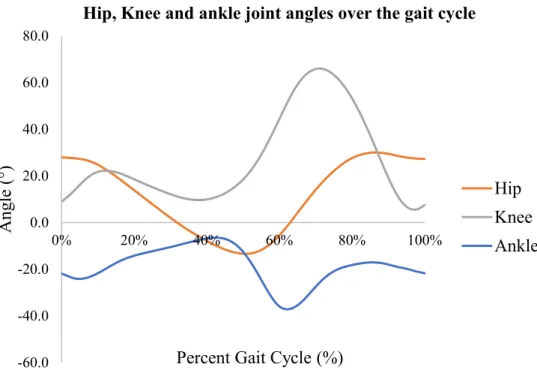
The human leg is usually modeled as a system of three rigid bodies with 7 degrees of freedom (DOF) that represent the movements of the three biological joints: hip, knee and ankle [15]. The hip and ankle joints have 3 DOF each, whereas the knee joint has 1 DOF. The movements in the sagittal plane are shown in figure 2-3. The range of motion (ROM), kinematics and kinetics of each DOF are different. Figure 2-4, 2-5 and 2-6 [22] show the angle, torque and power for each joint over the gait cycle for an adult during level walking with natural speed.
Figure 2-2: Anatomical body planes. Sagittal (red), median (green), and coronal (blue) [27]
Hip flexion Hip flexion Knee extension Knee extension Ankle dorsiflexion Ankle dorsiflexion Ankle plantarflexion Ankle plantarflexion Knee flexion Knee flexion Hip extension Knee flexion
-60.0 -40.0 -20.0 0.0 20.0 40.0 60.0 80.0 0% 20% 40% 60% 80% 100% Ang le (° )
Percent Gait Cycle (%)
Hip, Knee and ankle joint angles over the gait cycle
Hip Knee Ankle -0.60 -0.40 -0.20 0.00 0.20 0.40 0.60 0.80 1.00 1.20 1.40 0% 20% 40% 60% 80% 100% N.m/kg
Percent Gait Cycle (%)
Ankle, Kee and Hip Joint torques over the gait cycle
Hip Knee Ankle
Figure 2-5: Joint torques over the gait cycle Figure 2-4: Joint angles over the gait cycle
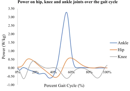
The power requirement for each joint is particularly important to understand for the design of active exoskeletons. For instance, as shown in figure 2-6, the hip joint has a positive average power, the knee power remains negative or null during most of the gait cycle and the power on the ankle is characterized by a sudden increase in the middle of the gait cycle to propel the body forward. This power burst is preceded by a negative power. The power distribution for each joint over the gait cycle is translated into design requirements and choices. For example, most exoskeletons add positive power on the hip and ankle and use dissipating elements on the knee [15].
2.1.3 Metabolic Cost of Walking
The metabolic cost of walking or metabolic rate expressed in Watts, defines the amount of energy (coming from food) consumed by the body per unit of time during walking. Although there is no established standard for assessing the performance of exoskeletons for human walking augmentation, the metabolic cost of walking is widely used as the main performance metric [16]. Precisely, the benefit of walking exoskeletons is examined by the amount of reduction in metabolic cost when walking with the device versus walking without it. Analysis of muscle electromyography (EMG) signals is also frequently used to assess the effect of wearing the exoskeleton on specific muscles during gait [1, 28, 29]. In general, reducing the EMG signals can result in a reduction in
-1.00 -0.50 0.00 0.50 1.00 1.50 2.00 2.50 3.00 3.50 0% 20% 40% 60% 80% 100% P owe r ( W /kg )
Percent Gait Cycle (%)
Power on hip, knee and ankle joints over the gait cycle
Ankle Hip Knee
the metabolic rate as the muscles are the major consumer of metabolic energy when performing physical activities [1].
2.2 Lower Limb Exoskeletons
2.2.1 Definition of an Exoskeleton
An exoskeleton is a wearable robotic device attached to the body to assist the human in performing physical activities such as walking, stair ascent and load bearing [15]. An exoskeleton is therefore a wearable robot that works in parallel with the human body as opposed to a prosthesis which replaces a limb in the body and works in series with the adjacent limb. The terms orthosis and exoskeleton are sometimes used interchangeably in the literature, however, an orthosis is an exoskeletal device that is designed to assist persons with a gait pathology, whereas, an exoskeleton is usually used to describe devices that augment and amplify the capabilities of typically developed persons [15].
2.2.2 Classification of Exoskeletons
The exoskeletons can be classified into different categories depending on the classification criteria such as the intended application, number of degrees of freedom, actuation type, etc. Broadly, exoskeletons can be separated into three groups: upper-limb, lower-limb and full-body exoskeletons. In this master thesis, we only focus on lower-limb exoskeletons. Among the classification criteria, distinction between exoskeletons by their intended application is crucial for the design, because each application usually has some specific requirements that are not relevant for the other applications. In terms of the application, exoskeletons can be classified into four groups: gait restoration, gait rehabilitation, industrial applications and human performance augmentation.
2.2.2.1 Gait Restoration Exoskeletons
The main objective of gait restoration exoskeletons is to allow persons with disabilities to walk independently and recover their capabilities to perform daily activities [30]. Therefore, the main performance measures for this type of exoskeleton are stability, safety, and ability to provide full support to the user to walk autonomously [16].
Several devices have been developed in this category [15, 16]. Depending on the intended population, these devices can be full-leg exoskeletons [31-33] or targeting selected joints of the lower limb such as active ankle foot orthoses [34-36] and active knee orthoses [37-39]. Currently, there are three commercial full-leg exoskeletons (ReWalk [40], Ekso [41], Indego [42]) approved by the US Food and Drug Administration to be used with patients suffering from a spinal cord injury [43]. The HAL (Hybrid Assistive Leg) is a product of the Japanese company Cyberdyne. It is the only commercial exoskeleton that uses surface electromyography (EMG) sensors to determine the user intent and apply a control signal accordingly [44]. Full-leg exoskeletons designed for gait assistance are typically bilateral and actuate the hip and knee joints in the flexion and extension movements. Kinematic and kinetics sensors are used by most of these exoskeletons to determine the user state [45-47].
Figure 2-7 shows some of the gait restauration exoskeletons.[48-50]
2.2.2.2 Gait Rehabilitation Exoskeletons
Gait rehabilitation exoskeletons are used by clinicians for gait training of patients suffering from locomotor dysfunctions or joint injuries. They are used in clinics as an alternative to trainings that rely entirely on the physical efforts of the therapist [16]. Although many therapeutic robotic systems are stationary such as the LOKOMAT [51], LOPES [52] and GaitTrainer [53]. Mobile
Figure 2-7: HAL-5 Exoskeleton (left) © Nilsson et al.; licensee BioMed Central Ltd. 2014 [48], H2 Exoskeleton © Bortole et al. 2015 [49], Ekso Bionics Exoskeleton Copyright © IEEE 2012 [50]
exoskeletons are also being used to provide more flexibility in the training. For instance, most of the gait restoration exoskeletons discussed previously are being used for therapeutic applications as well, in addition, some mobile exoskeletons were developed only for this purpose [54] [55]. 2.2.2.3 Industrial Exoskeletons
The exoskeletons in industry are primarily used to reduce the load on workers resulting from lifting and/or manipulating heavy objects, operating heavy tools, or standing for long hours [56]. These excessive loads result in poor health conditions for workers. For instance, each year, more than 40% of workers in the European Union report having back pain or neck and shoulder pain [57]. Over the last decade, many research teams have developed wearable exoskeletons for industrial use [56]. Specifically, those wearable devices support workers on shop floors for lifting loads [58, 59] and during still postures [60, 61]. The FORTIS exoskeleton from Martin Lockheed and ZeroG from Ekso Bionics are two commercially available industrial exoskeletons. They use a bilateral rigid frame to transfer the load of the tool being used to ground (see figure 2-8). [62]
2.2.2.4 Human Performance Augmentation Exoskeletons
The exoskeletons for human performance augmentation are built with the main objective of extending human physical capabilities beyond those acquired naturally. For example, allowing the user of the exoskeleton to lift heavy loads or walk long distances while spending less metabolic energy compared to walking without the exoskeleton. In this thesis, we only focus on exoskeletons
that are designed for the specific objective of augmenting human walking capacity. In other words, these walking exoskeletons are designed to reduce the fatigue and the metabolic energy consumed by a human during walking. These exoskeletons could improve the working conditions of individuals whose occupations require carrying and walking with heavy backpacks and equipment [63], such as soldiers and wildland firefighters. Although industrial exoskeletons are also designed for human performance augmentation, in most cases, they are not engineered for distance walking. Human walking is a complex operation in which multiple joints and muscles are involved simultaneously [26]. Therefore, walking exoskeletons need to be carefully designed to operate in accordance with the biological system.
The earliest device reported in the literature designed for human walking enhancement was patented in 1890 by Yagn [6]. His idea consisted in attaching a leaf spring to each leg to assist the user during walking, running and jumping. Although, there were some few other devices during the 20th century [64, 65], it wasn’t until the EHPA program was launched by DARPA that the field has witnessed extensive development. The scope of the DARPA initiative was to push the capabilities of soldiers beyond those of a normal human [66]. One of the most prominent devices developed under the DARPA program is the BLEEX [7]. Other featured devices from the same program include the MIT Exoskeleton [67] and Sarcos Exoskeleton [68]. Besides the DARPA program, there were many other lower limb exoskeletons developed in the U.S.A and worldwide [1, 9, 11, 20, 69]. This extensive and rapid progress over the last decade has resulted in a variety of designs that have been continuously optimized to achieve the best performance.
Reducing the metabolic cost of walking is a challenging task given that the body employs an optimal combination of parameters (step length, walking speed…etc.) to spend a minimum amount of energy [3]. Any change that alters one of these parameters, because of the use of an exoskeleton for example, is most likely going to increase the energy expenditure [1]. In fact, none of the exoskeletons developed under the EHPA program has demonstrated a reduction in metabolic cost for the user, usually it was an increase that was recorded [23] in spite of their technological sophistication [15]. Recently, with new innovative designs, locomotion exoskeletons started to bring an energetic benefit for the user [1, 12, 70].
2.2.3 Trends in the Design of Walking Augmentation Exoskeletons
There are many design trends and concepts of exoskeletons, each with its own advantages and limitations. The main design characteristics of an exoskeleton are:
- Actuation form: passive or active - Number of degrees of freedom - Physical interface: rigid or soft
In the remainder of this section, we explain each of these characteristics, mention their advantages and disadvantages, then, introduce examples of some walking exoskeletons having different combinations of these characteristics.
2.2.3.1 Passive Exoskeletons
The exoskeletons that use passive actuation systems do not have means of generating active positive power, instead, they only use a combination of passive elements such as springs and dampers to store and release energy at specific moments during the gait cycle [71-73]. Quasi-passive exoskeletons use Quasi-passive exoskeletons whom parameters could be controlled using an electrical signal such as a variable damper [23]. Clutches are also used in some passive exoskeletons to control the store and release of energy [74, 75].
Passive actuation systems reduce considerably the weight of an exoskeleton and do not limit its autonomy as no battery is needed except for a quasi-passive exoskeleton. However, passive exoskeletons are limited in terms of power they can add to joints.
2.2.3.2 Active Exoskeletons
Active exoskeletons have at least one active joint where positive power is generated by an actuator. Given that an actuation system could be chosen for a desired performance, active exoskeletons can be designed to achieve biological torque levels, therefore, their support for human locomotion could have a greater impact than passive exoskeletons. The main limitation of using motors in autonomous exoskeletons is the added weight and inertia caused by the actuator and its accessories. Also, the exoskeleton in this case needs a battery for its functioning, thus, adding more weight and limiting the autonomy.
A variety of actuators have been used in wearable robots including traditional systems such as hydraulic, pneumatic and electrical actuators and other systems such as Series Elastic Actuators (SEAs) and Pneumatic Artificial Muscles (PAMs). Eventually, those actuation systems differ in terms of power, size, weight and efficiency [76]. In general, for exoskeleton design, the emphasis when selecting an appropriate actuation system is on the power to mass ratio (specific power). A higher specific ratio is desired to achieve high torque and speed with a limited added mass.
2.2.3.2.1 Hydraulic Actuators
Hydraulic actuators can provide very high forces with a higher power to mass ratio compared to pneumatic and electric motors. However, these advantages come at the expense of a bulky hydraulic power supply, usually as an off-board unit which hinders the portability of the robot. For this reason, these actuators are commonly used in heavy duty industrial robots [77] but rarely in autonomous lower limb exoskeletons except for some military devices [7] [8].
2.2.3.2.2 Pneumatic Actuators and Pneumatic Artificial Muscles
Pneumatic actuators provide rapid movements with fast response and high specific power at a relatively cheap price [78]. Nevertheless, it is difficult to achieve precise position control with a pneumatic cylinder due to the different nonlinearities such as air compressibility [79]. In most cases, pneumatic cylinders include a piston which slides over the cylinder under the air pressure. Instead, PAMs (also known as McKibben muscles) are made of a rubber bladder surrounded by a braided fiber in a helical manner (figure 2-9). When the air inside the bladder is pressurized, the muscle assembly increases its diameter and contracts [80]. McKibben actuators are lightweight, intrinsically compliant and can produce high force magnitudes. For this reason, they were used in several exoskeletons and orthotic devices [29, 81-84].[85]
Despite the advantages of pneumatic actuators, their use for autonomous walking exoskeleton is very limited due to the need of an external air compressor. In most cases, they were used for rehabilitation devices meant to be used inside a laboratory.
2.2.3.2.3 Electric Motors
Electric motors are the most common type of actuation systems used in robotics applications [86]. Primarily, there are four types of electric motors: brushed Direct Current (DC) motors, Alternating Current (AC) motors, stepper motors and Brushless DC (BLDC) motors [87].
DC motors can be simply run by applying voltage from a DC power supply, while their speed can be controlled by varying the voltage [87]. However, their speed range is limited, therefore, they are adequate for applications where high speed is not required or a major concern such as in gait assistance and rehabilitation exoskeletons [88-90]. Another limitation of DC motors is the need for regular maintenance due to the use of mechanical friction brushes which limits their service life [91].
Stepper motors can move in small steps using an open loop control system [92]. Therefore, they are adequate for positioning applications. The major disadvantages of stepper motors are their low efficiency, relatively big size as well as the difficulty to run at high speeds [93]. In addition, the lack of a closed feedback control in stepper motors does not always guarantee the best performance [94].
AC motors are powered by an alternating current which is used to achieve the commutation of the fields in the rotor and the stator [95]. AC motors are not suitable for autonomous systems because batteries can only produce a direct current.
Figure 2-9: Pneumatic artificial muscle used in an ankle exoskeleton [85]
BLDC motors have the same structure as AC motors, but they create the alternating current from a DC source using special electronics and sensors as well as a control loop [96]. BLDC motors have many advantages over brushed DC motors. They can operate at high speeds while maintaining a relatively high torque, which is an important feature for augmentation exoskeletons. Furthermore, they have a longer service life as well as a higher power density [96]. However, BLDC motors require special drivers for their operation and control which add more complexity and cost. BLDC motors were used in several augmentation exoskeletons [11, 97, 98].
2.2.3.2.4 Series Elastic Actuators
Traditionally, actuators used in industrial robots have a stiff interface which allows a precise position control [99]. Conversely, in human interaction and biomimetic robotics context, a stiff interface with the environment is not desirable and in some cases can be dangerous to the user [100]. A Series Elastic Actuator (SEA), as its name indicates, has an elastic element attached in series with the actuator end [99] (see figures 2-11 and 2-12). This configuration brings many advantages that a stiff interface actuator lacks. In addition to ensuring a compliant safe interface with the environment (a human arm or leg for example), a major asset of SEAs is that precise force control becomes easier [101]. In fact, in a SEA, force control is achieved indirectly through precise positioning of the spring end. Using Hook’s Law and knowing the rigidity constant of the spring, the force is deduced by measuring the deformation of the latter [101]. Also, as most actuators have a gearbox, in the presence of shocks, the series elastic element acts as a mechanical filter by absorbing any impacts that could damage the gears [102]. SEAs are more efficient as well since the spring can store and release energy, therefore, reducing the power requirement of the actuator [103]. [100]
Motor Gearbox Load Elastic
element
Figure 2-10: Schematic of a SEA Figure 2-11: SEA used in a walking
2.2.3.2.5 Magnetorheological Actuator
Magneto-Rheological (MR) are a certain category of smart fluids that change their viscosity in the presence of a magnetic field [104]. The viscoelasticity of these fluids can be increased by increasing the magnetic field applied to them.
One application of this interesting property is the MR actuator. An MR actuator is made of an electric motor coupled with an MR clutch which can behave as a brake as well by controlling the magnetic field intensity [105]. When positive power needs to be transmitted, the MR actuator acts as a motor coupled with a clutch, when damping is needed, the MR actuator acts as a brake while the motor is turned off [104]. This feature of switching between a clutch and a brake using one component is an important asset in some applications such as knee assistive devices where both modes are needed. However, one disadvantage of MR actuators is their large size and mass [105]. MR actuators in the context of exoskeletons were used for the knee joint [104, 106], as the torque on this joint has a damping effect on most of the gait cycle [15].
2.2.3.2.6 Transmission Systems
The actuation systems that are based on electric motors usually include a transmission system that amplify the torque produced by the motor. These transmission systems include conventional systems such as gear drives, belt drives and Ball screws, and non-conventional systems such as the harmonic drives which have high reduction ratios, near-zero backslash and compact size (see figure 2- 12) [86]. Harmonic drives were used in many robotics applications requiring precision positioning [107]. In the context of exoskeletons, harmonic drives were used for rehabilitation exoskeletons [11, 44] and rarely for augmentation exoskeletons because of the need for relatively high speeds. [108]
Figure 2-12: Harmonic drive. Copyright © IEEE 2017. [108]
2.2.3.2.7 Selection of the Actuation System
Table 2-1 summarizes the advantages and disadvantages of the types of actuation systems discussed above. The advantages of these actuators are in general complementary. Therefore, selecting one type from another could be a challenging design decision given that the actuation system represents a significant part of an exoskeleton cost and is critical to its performance. For this reason, the design choice needs to be guided by a thorough understanding of the application requirements such as speed and torque as well as size and mass limits. For instance, hydraulic and pneumatic actuators which need compressors for their operation are not suitable for autonomous exoskeletons. Electric motors are the best actuation option for autonomous exoskeletons. Specifically, for an ankle exoskeleton, BLDC motors offer high power density, that is, they provide high power while having low mass and size.
Table 2-1: Actuation systems
Actuation type Main advantages Disadvantages
Hydraulic High power to weight ratio Need for an external compressor Frequent maintenance
Pneumatic High power to weight ratio Compliant
Need for an external compressor Frequent maintenance
Brushed DC motors Simple to operate and control Relatively cheap
Limited service life Limited range of speed Stepper motors Position can be controlled with
an open loop control
Large size and mass Low efficiency Brushless DC motors High power to mass compared to
other electric motors Wide range of speed
Require electronic drivers
Relatively expensive compared to other electric motors
Series elastic actuators Allow for safe interaction with the environment
Allow for high precision force control
Large size and mass
Magnetorheological actuators
Can operate as a brake and a clutch
2.2.3.3 Rigid and Soft Physical Interfaces
The physical Human-Robot (pHR) interface of a wearable robot is the set of materials and components used to transfer the mechanical power from the robot to the user [109]. For many years, exoskeletons for augmentation and walking assistance were built using rigid frames as the pHR interface. The frame is commonly made of rigid links and joints attached to the user body at some locations using straps and belts. Rigid physical interfaces have caused substantial issues for exoskeletons including the added inertia of linkage and altering of natural gait as well as misalignment of exoskeleton and biological joints [83]. Recently, a new research direction is being investigated to improve the pHR interface of exoskeletons. It consists of developing exoskeletons called “soft exosuits or soft exoskeletons” [83] which incorporate soft materials such as textiles and webbing to transfer the force to the user (see figure 2-14). The introduction of soft exosuits has alleviated many of the challenges associated with conventional rigid exoskeletons. For instance, the use of textile makes the exosuit transparent to the user, that is to say, the exosuit does not interfere with the natural movements of its wearer [110]. Additionally, exosuits are significantly lighter than conventional exoskeletons. As a result, exosuit can potentially be more efficient because rigid exoskeletons spend a part of their mechanical energy to overcome their own weight and inertia. Actuation in soft exosuit is done through compliant actuators such as McKibben [83] or using cable-based transmission systems [13]. A unique feature of exosuits is the multiarticular actuation, that is to say, the actuation system of the exosuit along with a custom-designed mesh of webbing allows transmission of mechanical power to different joints simultaneously (see figure 2-14 C). Exosuits do have some disadvantages; however, for instance, they don’t support compressive loads (such as backpacks) and they are limited in maximum torque and bandwidth [50]. Besides, when the suit is tensioned, there are shear forces between the attachment straps and the user skin [111].[13]
2.2.3.4 Number of Degrees of Freedom
There are three joints on the human's lower limb: hip, knee and ankle. Early developed augmentation exoskeletons were in most cases made of bilateral frames with a combination of passive and active joints parallel to each of the biological joints with many degrees of freedom (DOF). For example, the Body Extender exoskeleton had 22 actuated DOF [10]. Although this design was adopted for many load-carrying exoskeletons, it has imposed key challenges which resulted in many of these exoskeletons not being able to reduce the energy consumed by the user when walking with the exoskeleton compared to normal walking [16]. Among these challenges, the mass and inertia that these devices add to the user as well as the lack of kinematic compliance between the user limb and the exoskeleton frame [112]. This lack of compliance is featured for example in the misalignment between the biological and exoskeletal joints which can be as large as 10 cm [113]. From a control perspective, a multi-joint exoskeleton requires the control system to handle the coordination of different joints during walking to match the natural gait of the user. Because of all these hurdles, some researchers focused on developing single joint exoskeletons to decrease the complexity and have more control over the design parameters [21, 114]. Moreover, with a single DOF exoskeleton, it is much easier to study the physiological effect of the control and design parameters [115].
Most single DOF walking exoskeletons add positive power on the hip or ankle joints because these joints have a positive average power over the gait cycle [1, 12, 21, 98, 116, 117]. Among hip
Figure 2-13: Harvard Wyss institute exosuit. © Panizzolo et al. 2016 [13]
exoskeletons that were developed [89, 114, 116], some were able to reduce the metabolic cost of walking [70, 117]. Ankle exoskeletons have more potential to reduce walking energetic cost because during the push up phase, the muscles produce a large peak of power on the ankle joint to lift the body and push it forward (see figure 2-6). Some ankle exoskeletons which supplemented the biological torque during this short phase could reduce the metabolic cost of walking [1, 19, 118]. In the next section, we present and review the design of some of these ankle exoskeletons.
2.2.4 Ankle Exoskeletons for Reducing Metabolic Cost of Walking
Several ankle exoskeletons were developed to reduce the metabolic cost of walking. The ankle joint delivers a high power at the end of the stance phase to push the body forward. For a person with 80 kg weight, the ankle plantar flexion torque can be as high as 96 Nm [22]. For this reason, researchers designed ankle exoskeletons to supplement this biological torque by an artificial torque that could reduce the energy expenditure during walking. In this section, we present some of these ankle exoskeletons and highlight their design characteristics.
2.2.4.1 Unpowered Ankle Exoskeleton from Collins et al.
The exoskeleton developed by Collins et al. is a lightweight unpowered ankle exoskeleton. It was made of a spring attached to a mechanical clutch by a rope [1]. Those components were attached to the back of a lightweight composite structure worn around the shank (see figure 2-15 A), thereby, providing a mechanical behavior similar to that performed by the calf muscles and tendons. During normal walking, soleus and medial gastrocnemius muscles stretch slowly during the single stance phase then recoil rapidly at the end of the late stance allowing the release of mechanical energy stored on the Achilles tendons [119]. This clutch-like behavior of the muscles and spring-like behavior of the Achilles tendons was the motive behind the design of the exoskeleton by Collins et al. [1]. The mechanical clutch placed in parallel to the calf muscle engages the spring placed in parallel to the tendons during the stance phase of the gait cycle to store the energy, then disengages it to release the stored energy at the beginning of the swing phase [1]. Figure 2-15 B shows a CAD model of the clutch mechanism.
Tests were carried out on healthy subjects wearing the exoskeleton on both legs while walking at a speed of 1.25 m s-1. The torque produced by the exoskeleton is similar to the human ankle joint torque but much lower in magnitude. Different values of spring stiffness were tested to examine
its effect on the metabolic cost of gait. The exoskeleton reduced the consumed metabolic energy by 7.2 ± 2.6 % compared to normal walking [1]. This reduction was also associated with a reduction in the soleus muscle activity. In addition, it was shown that a particular value for spring stiffness was optimal, increasing or decreasing this value results in more energy consumption. The main limitation of this unpowered exoskeleton is the inability to provide higher torque due to lack of an active power source. In addition, it is not yet well understood how this approach affects the natural human gait on the short term and long term because this approach relies entirely on the power generated by the biological system.[1]
2.2.4.2 Pneumatic Ankle Exoskeleton from Malcolm et al.
Malcolm et al. studied the effect of the actuation onset on the metabolic cost reduction using a powered ankle exoskeleton [19]. This exoskeleton uses a McKibben pneumatic muscle to produce an assistive plantar flexion torque on both legs. This simple lightweight structure adds only 0.67 kg per leg. During the experiments, five actuation onset values were tested: 13, 23, 34, 43 and 54% (percentage of the gait cycle). The actuation offset was set at toe off in all cases.
The experiments were performed on eight typically developed subjects wearing the exoskeleton while walking on a treadmill. The five actuation onset conditions were tested for each participant
Figure 2-14: (A) a schematic of the unpowered exoskeleton developed by Collins et al. (B) the mechanical clutch [1]
in addition to walking with the exoskeleton unpowered which was used as a reference [19]. The highest reduction of metabolic energy was of 6 ± 2% compared to walking without the exoskeleton. This reduction occurred on the 43% onset condition which is just before heel contact of the other leg [19].
Despite the significance of the result achieved in this study, the tested exoskeleton was tethered to an off-board air compressor. Achieving the same reduction of metabolic rate with an untethered exoskeleton would be more challenging, still, this work gives proof that reducing the metabolic energy consumption is achievable with a powered exoskeleton when the actuation timing is optimal.
2.2.4.3 Achilles Exoskeleton
Achilles is a powered exoskeleton developed to reduce the metabolic cost of walking [20]. The design of Achilles consists of a rigid structure made of two hinged parts: the shank shell and foot shell. A linear actuator was attached from one end to the shank shell and from the other end to a flexible link fixed to the foot shell (see figure 2-16). The set composed of a flexible lever arm and linear actuator form a SEA. Meijneke et al. used a SEA to store and release the negative power provided by the ankle joint during the stance phase, thereby, reducing power requirements of the motor. To further improve the design of the device, an optimization study was conducted with the goal of maximizing the power of the exoskeleton while minimizing its mass by varying the dimensions of the linkage mechanism and stiffness of the lever arm for different motor and gears combinations. The final prototype of the device can output a maximum mechanical power of 80.2W.
The device was tested on seven healthy subjects by collecting kinematic and kinetic data in addition to carbon dioxide consumption in three conditions: waking without the exoskeleton (baseline), walking with the exoskeleton unpowered and walking with the exoskeleton powered on. The maximal assistance torque applied by the exoskeleton during the trials was 0.4 Nm/kg. The experiments showed that the exoskeleton could not reduce the metabolic cost of walking. The authors explained this by a number of reasons related to hardware and control aspects such as the interference of the actuator with the natural gait, particularly during the swing phase and early stance phase. During these phases, no assistive torque is provided. However, the actuator was not completely transparent as it applied a force to match the natural movement of the subject. Other
exoskeletons using unidirectional actuators [1, 12, 19, 21] allow free movement to the user during these non-assistance phases.[98]
2.2.4.4 Powered Ankle Exoskeleton from Collins et al.
In an effort to facilitate the understanding of how human adapts and reacts to an exoskeleton, Collins et al. developed an emulator system that includes two end effectors in the form of ankle exoskeletons (Alpha and Beta) tethered through Bowden cables to a powerful off-board electric motor [21] (see figure 2-17). While the main goal of this work was not to develop an autonomous exoskeleton, important improvements were brought to the design of the two exoskeletons to achieve high torque and high bandwidth while keeping their mass at a low level. Both of the exoskeletons had a rigid frame attached to the leg in three points: the shank, the heel and the toe areas. Each frame has a shank and a foot section. The foot section extends posterior to the ankle joint to provide a lever arm. When the Bowden cable is pulled by the motor it compresses the shank section downward and pulls the lever arm upward, thereby, creating a plantar flexion torque. The main difference between the two exoskeletons was the series elastic element (figure 2-17). In the Alpha version, two leaf springs were attached on the lateral and medial sides of the foot frame, thus increasing the envelop of the exoskeleton. In the Beta version, the envelope was reduced by introducing a coil spring.
During walking tests to evaluate the mechanical performance of the two devices, the average torque produced by the Alpha and Beta exoskeletons was 80 Nm and 87 Nm respectively, while the
Figure 2-15: The Achilles exoskeleton. Copyright © IEEE 2016 [98]
maximum torque was 119 Nm and 121 Nm. In terms of weight, both exoskeletons were lightweight with a total of 0.835 kg and 0.875 kg for the Alpha and Beta versions respectively. [21]
2.2.4.5 Powered Ankle Exoskeleton from Mooney et al.
Mooney et al. developed an exoskeleton capable of providing high positive mechanical power during powered ankle plantar flexion phase [12]. Ankle exoskeletons commonly apply torque by exerting a force in parallel to the leg within a distance behind the ankle joint [1, 21, 98]. This choice limits the lever arm to a short distance as it is impractical to increase the envelope of the exoskeleton far behind the ankle. To overcome this challenge, the exoskeleton built by Mooney et al. applies the force normal to the shank using a winch actuator that pulls two struts attached to the user’s boot (see figure 2-18). The struts in this configuration allow for a large lever arm, thus reducing the force requirement of the motor to produce a given torque. In addition, the fiberglass struts reduced significantly the weight of the exoskeleton [12]. Applying force in the normal direction to the leg also reduces the slip of the frame attached to the shank compared to applying tangential forces, therefore, improving user comfort while wearing the exoskeleton [12]. The mass added by the exoskeleton on the foot and shank was 2.12 kg (1.06 kg per leg).
The exoskeleton was tested on healthy participants for both loaded and unloaded walking. On the loaded walking experiment, the subjects wore a 23-kg vest while walking at a speed of 1.5 m/s. On the unloaded test, subjects walked on the treadmill at a speed of 1.4 m/s. The energy consumption measurements on the loaded and unloaded locomotion conditions showed a reduction in metabolic cost of 8 ± 3% [12] and 10 ± 3% [97] respectively when walking with the exoskeleton compared
Figure 2-16: (A) Alpha exoskeleton (B) Beta exoskeletons. Copyright © IEEE 2015 [21]
to walking without the exoskeleton. During the two tests, the exoskeleton delivered an average mechanical power per gait cycle of 23± 2 W (11.5 per ankle) and 26 ± 1 W (13 per ankle) respectively.
This study marks the importance of concentrating efforts on developing lightweight and powerful exoskeletons that can add substantial mechanical energy without impeding the natural user movement. [118]
2.2.5 Design Challenges
The variety of design solutions adopted in building exoskeletons is an indication of the different challenges faced by researchers working to improve the performance of these devices. Despite many years of research and development in the field, there are still several challenges in the design of exoskeletons for walking assistance and augmentation. The main design challenges could be summarized as follows:
1. Mass and inertia
The exoskeletons are generally physically attached to the user in parallel to his limbs, therefore, as the user moves, he perceives the added mass of the device that in most cases makes the movements more difficult and requiring more metabolic energy. To illustrate this, if a mass of 4 kg is attached to the foot, it will increase the metabolic rate of walking at normal speed by nearly 36% [24]. The added mass could be supported by the device actuators; however, this increases power requirement and complexity of the control system.
Figure 2-17: Mooney et al. exoskeleton. © Mooney and Herr. 2016 [118]
2. Mechanical Power
Muscles in the human body can generate very high forces while being compact. For instance, for a male of 79 kg weight and 1.75 m high, the muscles can provide up to 1867 N during ankle plantar flexion [83]. For an exoskeleton to achieve the same levels of force, it needs high power actuators. However, increasing the mechanical power usually also increases the weight and size of the device. Therefore, using actuators with a high power to mass ratio could give the best compromise.
3. Control System
Naturally, the human body employs the best gait parameters to minimize energy expenditure during walking including the step length [3], joints kinematic [120] and arm swinging movements [121]. For this reason, the exoskeleton control system needs to work in perfect synergy with the biological system. Any disturbance of the normal gait could result in an increase of the metabolic energy. Additionally, for practical use, the exoskeleton needs to adapt to different scenarios such as walking on flat or rough terrain and level or upslope walking. The current control technology used in many exoskeletons relies on a hierarchical architecture that could be decomposed in three control layers [122]. The higher control layer monitors the gait cycle transitions and activity modes of the user. The mid-level layer translates the detected state of the user to a desired input, for example, the input can be a force or position reference signal. The low-layer is the execution layer that uses feedback and feed forward control loops to minimize the error between the desired and the current state.
4. Transparency
A transparent exoskeleton does not interfere with the natural gait and cadence of the user. In the best scenarios, the exoskeleton must not limit the natural ROM or impede any biological degrees of freedom. Improving the exoskeleton transparency can be achieved both at the mechanical and control levels, for example by reducing the weight and size of the device and implementing biomimetic control strategies.
5. Safety
Although safety does not influence the core functioning of the exoskeleton, it is of vital importance for the user. Moreover, augmentation exoskeletons are usually used by a healthy population, thus, they operate at higher speeds and generate higher mechanical power than other types of exoskeletons. For this reason, user safety must be a core element in the exoskeleton design. Similar to transparency, safety can be achieved by mechanical mechanisms and control software. For example, mechanical stops can be used to limit the movement of the exoskeleton to the maximum ROM of a joint and the control algorithm can contain a safety layer that frequently monitors the state of the device as well as the user to detect any abnormal situations.
6. Autonomy
Unlike tethered exoskeletons where the actuation is provided by an off-board unit, an autonomous exoskeleton carries its own hardware including the actuation system and thus can be used outside the lab. Additionally, for an autonomous exoskeleton, the battery limits the autonomy of the device to a certain duration. Increasing the device autonomy is not only limited by the technological development in batteries because improving the efficiency of the exoskeleton will also increase the autonomy.
CHAPTER 3 RATIONAL OF THE PROJECT
3.1 Summary of the Problem
Powered ankle exoskeletons including those that reduced the metabolic cost of walking add a mass to the user around the ankle joint. This mass that is far from the hip joint requires more metabolic energy from the user to walk when the exoskeleton is not powered on. Therefore, when the exoskeleton is powered on, it loses a part of its mechanical energy to compensate for its added mass. As a result, its benefit to the user in terms of reducing the metabolic expenditure during walking is limited.
3.2 General Objective
The general objective of this project is to develop an ankle exoskeleton with a minimum added distal mass compared to existing autonomous powered ankle exoskeletons providing at least 50 Nm of assistive plantar flexion torque.
3.3 Specific Objectives
The exoskeleton is a biomechatronic device integrating different subsystems. These subsystems guided us in defining the specific objectives for this project as follows:
1. OS1. Develop the mechanical system of the exoskeleton.
a. Develop a design concept that reduces the distal mass and increases the torque provided by the exoskeleton
b. Design and assemble the actuation unit
c. Perform detailed design including optimization studies for the exoskeleton components
2. OS2. Develop the control system of the exoskeleton.
d. Develop and implement an algorithm for real time detection of gait phases e. Build the electronic circuit for the gait detection system
f. Integrate the gait detection system with the motor controller
g. Develop a graphical user interface for the control and monitoring of the device 3. OS3. Assemble and evaluate the exoskeleton
h. Assemble the exoskeleton components and ensure synergic integration of the hardware and the software.
i. Perform mechanical testing for the exoskeleton to determine the mechanical efficiency of the actuation system
j. Perform human walking trials with the exoskeleton to evaluate its effect on the activity of the ankle muscles.
ARTICLE 1: DESIGN AND DEVELOPMENT OF A
LIGHTWEIGHT ANKLE EXOSKELETON FOR HUMAN WALKING
AUGMENTATION
The following article was submitted to Elsevier Mechatronics journal on March 8th, 2018. Yacine Bougrinat, Sofiane Achiche, Maxime Raison.
Abstract
Most of powered ankle exoskeletons add considerable distal mass to the user which limits their capacity in reducing the metabolic energy of walking. The objective of the work presented in this paper is to develop an ankle exoskeleton with a minimum added distal mass compared to existing autonomous powered ankle exoskeletons, while providing at least 50 Nm of assistive plantar flexion torque. The proposed exoskeleton uses Bowden cables to transmit the mechanical force from the actuation unit attached to the waist to the carbon fiber struts fixed on the boot. As the struts are pulled, they create an assistive ankle plantar flexion torque. A 3d-printed brace was attached to the shin to adjust the direction of the cables. A design optimization study was performed to minimize the mass of the struts, thereby limiting the total added distal mass, attached to the shin and foot, to only 348 g. The main result obtained from walking tests was the reduction of the soleus and gastrocnemius muscles activity by a maximum of 37% and 44% respectively when walking with the exoskeleton compared to normal walking. This result shows the potential of the proposed exoskeleton to reduce the metabolic cost of walking and emphasizes the importance of minimizing the distal mass of ankle exoskeletons.
Keywords
Lower limb exoskeleton, human augmentation, ankle exoskeleton, wearable robot Funding
This work was supported by the Discovery Grant (RGPIN-2014-06289) of the Natural Sciences and Engineering Research Council of Canada, the Fond de Recherche Nature et Technologies (NSERC) and Ingénierie de Technologies Interactives en Réadaptation (INTER).
4.1 Introduction
Walking while carrying heavy loads is a fundamental skill in daily activities of some professions. For example, soldiers are often required to walk while carrying heavy backpacks that weigh more than 50% of their lean body mass [1]. Firefighters also wear protective equipment and breathing apparatus that negatively impact their physical conditions [2]. Several exoskeletons have been developed to reduce the effect of heavy payloads during walking [3, 4]. The design of these exoskeletons varies from full-leg exoskeletons [5-9] to single joint exoskeletons that assist the user at the hip [10, 11] or at the ankle [12-14]. It is important to note that the most commonly used metric to evaluate these exoskeletons is the metabolic cost of walking which is the energy consumed by the human body during walking [4, 15]. Another common metric is the analysis of electromyography (EMG) signals to examine changes in muscle activation [15]. Both of these metrics will be referred to in the rest of the paper.
Among single joint exoskeletons, ankle exoskeletons have shown great potential in reducing the metabolic cost of walking [13, 16, 17]. The power generated on the ankle joint during the push off phase is the largest compared to other joints of the leg [18]. Therefore, adding positive power during this phase on the ankle can have a beneficial effect on the walking energetics. There are different design approaches for ankle exoskeletons in the literature; one of the most distinctive design features is the actuation form as either passive or active, as described in the two next paragraphs, respectively.
Passive exoskeletons are suitable for augmentation on the ankle joint as the power on the ankle has a negative period where energy can be stored in an elastic element and a positive period where the stored energy can be released. Using this approach, Collins et al. developed a lightweight device equipped with a passive clutch mechanism attached to a series spring to augment the ankle torque during push off [19]. Tests performed on healthy typically developed subjects walking with this device showed a reduction in metabolic cost by approximately 7% [13]. The advantage of passive ankle exoskeletons is that they are lightweight and simple; however, the positive power they provide is limited compared to active exoskeletons, due to the lack of actuators.
Pneumatic actuation was used in many ankle foot orthoses for both rehabilitation and gait training purposes [20-23]. Pneumatic actuators have a high specific power [24], and thus they represent a good option for augmentation exoskeletons. Malcolm et al. performed tests on able bodies wearing
![Figure 2-1: Gait cycle phases. Copyright © 2008 IEEE [15]](https://thumb-eu.123doks.com/thumbv2/123doknet/2325640.30277/17.918.121.802.721.980/figure-gait-cycle-phases-copyright-ieee.webp)
![Figure 2-7 shows some of the gait restauration exoskeletons. [48-50]](https://thumb-eu.123doks.com/thumbv2/123doknet/2325640.30277/22.918.235.684.492.793/figure-shows-gait-restauration-exoskeletons.webp)
![Figure 2-8: The FORTIS exoskeleton [62]](https://thumb-eu.123doks.com/thumbv2/123doknet/2325640.30277/23.918.291.625.536.819/figure-the-fortis-exoskeleton.webp)
![Figure 2-9: Pneumatic artificial muscle used in an ankle exoskeleton [85]](https://thumb-eu.123doks.com/thumbv2/123doknet/2325640.30277/27.918.304.610.107.405/figure-pneumatic-artificial-muscle-used-in-ankle-exoskeleton.webp)

![Figure 2-13: Harvard Wyss institute exosuit. © Panizzolo et al. 2016 [13]](https://thumb-eu.123doks.com/thumbv2/123doknet/2325640.30277/32.918.272.643.105.351/figure-harvard-wyss-institute-exosuit-panizzolo-et-al.webp)