HAL Id: hal-01276665
https://hal.archives-ouvertes.fr/hal-01276665
Submitted on 19 Feb 2016
HAL is a multi-disciplinary open access
archive for the deposit and dissemination of
sci-entific research documents, whether they are
pub-lished or not. The documents may come from
teaching and research institutions in France or
abroad, or from public or private research centers.
L’archive ouverte pluridisciplinaire HAL, est
destinée au dépôt et à la diffusion de documents
scientifiques de niveau recherche, publiés ou non,
émanant des établissements d’enseignement et de
recherche français ou étrangers, des laboratoires
publics ou privés.
Generic error model of human-robot interaction
Jérémie Guiochet, G Motet, C Baron
To cite this version:
Jérémie Guiochet, G Motet, C Baron. Generic error model of human-robot interaction. 3rd IARP
- IEEE/RAS - EURON Joint Workshop on Technical Challenges for Dependable Robots in Human
Environments, Manchester, UK, Sep 2004, Manchester, United Kingdom. �hal-01276665�
Generic error model of human-robot interaction
J. Guiochet
LESIA-INSA/LAAS-CNRS
Toulouse, France
guiochet@univ-tlse2.fr
G. Motet and C. Baron
LESIA-INSA
Toulouse, France
gilles.motet@insa-toulouse.fr claude.baron@insa-toulouse.fr
Abstract: Wrong human-robot interactions are at the origin of severe damages. Safety requirements ask the analysis of these interactions. At first, erroneous inter-actions have to be identified. In this paper, we propose to use UML (Unified Modeling Language) to specify human robot interaction. Then, generic error models, associated with the message feature provided by UML, are presented. These error models allow interaction er-rors to be automatically deduced from the modeling of the human-robot interactions. The use of these generic error models is illustrated on a medical robot for tele-echography.
Keywords: human robot interaction, error model, UML, FMECA, medical robot
1
Introduction
Safety was previously defined for industrial robots as the prevention of damage to the robot itself and its en-vironment, and particularly the human component [1]. It can now be defined as the property of a robot to be "free from unacceptable risk" [2]. For human centered robots as medical robots this topic has became critical, and it is obvious that safety previously defined as an absolute property must now be expressed in a relative and probabilistic way: there is always a residual risk. Therefore it is necessary to reduce the risk to an ac-ceptable level using a complete risk management activ-ity [3]. During this activactiv-ity, the study of interactions between human and robotic system plays a major role in risk analysis. Nevertheless, the integration of human factors in the risk management standards is still in work [4, 5]. Moreover a significant barrier for designers is that many concepts and analysis techniques of human factors are unfamiliar and difficult to apply.
One objective of this paper is to present an approach to handle human-robot interaction in a safety analysis. We focus on modeling human-robot interaction but not on technical means used for its design. We first present a way to model human-robot interaction with the object oriented Unified Modeling Language (UML) as previ-ously presented in [6]. We specially focus on human-centered aspects of this notation for human-robot
in-teraction. Then a second section presents an analysis of the failure modes of the interactions based on the previously identified UML diagrams. In this section eleven generic errors for human-robot interaction are presented. This approach have been applied to the anal-ysis of a medical robot for tele-echography (TER) [7]. TER is a robotic system. The slave robot is tele-operated by an expert clinician who remotely performs the ultrasound scan examination. A virtual probe is mounted on the master interface device. The real probe is placed on the slave robot end-effector. For the exam-ples presented in this paper we focus on the slave site analysis where safety is critical.
2
Human-robot interaction
mod-eling
A collaboration between specialists of the business in which the robot will be implemented (doctors for in-stance for a medical robot) and system engineers is re-quired to specify interactions. Thus it is fundamental that the models can be understood by all the actors of the development process (also called stakeholders). For those reasons we focus on the use of certain UML dia-grams easily readable by non specialists.
It is important in order to describe interactions to rep-resent the distribution of work between human actors and technological parts. This helps in defining non am-biguous and consistent tasks for humans who are using the robot. In human factors studies, this is also called function allocation and task analysis [8]. In our case we found that the use cases diagrams [9] and sequence di-agrams (both are UML didi-agrams) are useful to specify an allocation of work. Moreover, in a first step it is pos-sible to employ use cases to model the system without the robot. This approach is close to business modeling if we consider that the robot will be used for a specified task. During this step, "business modeling increases the understanding of the business and facilitates communi-cation about the business" [10].
For the considered example, the slave TER system, the use case diagram in figure 1 models the common ul-trasound scan examination without the robot system. In
Patient Diagnose Perform Ultrasound Scan
Patient Management Ultrasound Scanner Management Specialist Ultrasound Scanner
Figure 1 : Use case diagram: global view of ultrasound scan
examination
TER Control System
Operator
Patient Management Robot Management
Patient Master Site
Perform Ultrasound Scan
Slave Robot Ultrasound scanner
<<include>>
Figure 2 : Use case diagram of the TER slave control system
this diagram actors are identified. An actor character-izes an outside user or related set of users who interact with the system [11]. It is possible for an actor to be a human user (like the Specialist) or an external system (like the Ultrasound Scanner). This is really useful in socio-technical systems, and particularly in human cen-tered robotic systems. In the business modeling, use cases are useful to specify and classify each goals of the actors of the system. Moreover a more precise tex-tual specification (not presented here for readability) of each use case help developers to make design choices.
This diagram is then completed with use cases de-rived from the integration of the robot in the ultrasound scan examination. The use case diagram of figure 2 represents main requirements for the slave control sys-tem of the TER project. For the TER project we choose to represent two external systems as actors: the Master Site and the Robot. The Master Site replaces the actor Specialist who is in charge of performing the examina-tion. The Ultrasound scanner is also presented as an actor. Even if the management of this device is an out-side use case of the control system, this representation stresses on the relationship between this device and the TER control system (in fact the robot manipulated the probe which is a part of the scanner).
: Operator
: TER Control System
: Patient : Robot
Prepare Patient Calibrate for Patient corpulence
Identify Patient position
Identify Robot configuration Calibrate Robot
Calculate Patient model
Calculate Robot model
Install
Set air pressure in artificial muscles Launch teleoperation
Install Robot Connection with Master Site
Set power supply
Figure 3 : Sequence diagram of the main scenario of use case
Robot Management
Those use cases only express goals for the actors [12]. They specify a framework of the interaction. But to describe how those goals are performed, we have to specify the interactions themselves. This can be done with textual descriptions but UML semantics proposes to use interaction diagrams (sequence and collaboration diagrams) which core element is the message. On se-quence diagram of figure 3, the main interaction for the use case Robot Management is presented. This nota-tion of tasks is also useful to specify a sequence order, which can be essential for safety. It is important to note that by definition, sequence diagrams just specify pos-sible scenarios (descriptive models). Nevertheless we use those diagrams as prescriptive models to establish a safe order of messages, because they are easily under-standable by non experts of UML modeling.
This approach produces high level models. For any safety critical project those models should be made be-cause they lead to a more consistent function allocation, and furnish non ambiguous task description. Later the diagrams can be refined (for instance the sequence di-agrams) for design step. Moreover, an important point developed in the next section is that those diagrams can be used for safety analysis and more particularly for hu-man robot interactions analysis.
3
Failure mode interaction
analy-sis
The notion of failure mode is close to the notion of er-ror; both concepts will be equally used in this section. Most of interaction failure modes are human errors. As a potential source of harm (a hazard), human error has to be analyzed during the step of hazard identification and risk estimation. Although there are a variety of
Interaction
Robotic System message1 (parameters)
message2 (parameters)
Interaction name Object name Message
name
Message return
(usually indirectly suggested)
Sending event Receiving event Message treatment Message parameters return1(parameters) retour2(parameters) Receiving event Sending event T ime : Human Actor
Figure 4 : Elements of a human robot interaction
techniques (the most relevant and complete technique is certainly the Technique for Human Error Rate Pre-diction [13, 14]) and tools [15], the complexity of hu-man error classification and cognitive theory [16] usu-ally leads engineers to the use of design checklists and guidelines [17] for the design of human machine in-terfaces. Nevertheless, as noted in [18], guidelines are not sufficient for innovative projects (such as medical robots).
The aim of this section is to propose to developers, tools to identify interaction failure modes. We propose an approach to perform analysis of human-robot inter-actions including human errors analysis. First, to be consistent with system development process we base our approach on UML models. Second, we do not use human error techniques but FMECA (Failure Modes Effects and Criticality Analysis)[19] which also covers interactions analysis.
Analysis techniques such as FMECA consist at first in identifying errors of the studied system elements. These errors are often specific to the application lead-ing to specific studies for each new application. How-ever, to realize a more systematic error identification step, one can sometimes use some generic error mod-els, which can be applied independently from the appli-cation characteristics. In UML, interactions are repre-sented with two diagrams: the sequence diagram (pre-viously introduced) and the collaboration diagram. We will not use the collaboration one which is really close to the sequence one [20]. The core element of those interaction diagrams is the concept of Message. The notion of Action is also an important feature of UML to describe behaviors. But we don’t use this concept because its semantics changed a lot from version UML 1.4 [21] to 1.5 [20] and now to 2.0 [22].
As presented in figure 4, an interaction is composed of a sequence of messages. The different elements of a message are:
• the interaction it belongs;
• the next and previous messages in the interaction;
• the objects that send and receive the message;
• the sending and receiving events;
• the parameters (number, type and value);
• the implicit response (defined by its arguments,
sending and receiving events);
• the period of the message treatment.
Then possible errors for a message have been estab-lished based on all these elements [23].
Types of errors
First, a message belongs to an interaction, and a send-ing of a message non-planned is an error, which of-ten happens in human-machine interface manipulation. Generally, this type of error can be extended with a first error model:
E.1. Sending of a message not belonging to the planned interaction.
A second point dealing with the message order can also leads to errors. Indeed, a user having many mes-sages to send might inverse or forget one of them. This type of error can be extended as two types of error mod-els:
E.2. Execution of one or several messages in a wrong order.
E.3. Omission of a message among an interaction. A message is sent by an object to another object sup-posed to receive it. The receiver must exist. This type of error allows to formulate a new generic error:
E.4. Lack of an instance to receive the message. This type of error can appear in a detailed sequence diagram showing all the objects of an interface. Some objects can change their state and become inaccessible. The sending of the message then depends on the state of the system.
Characteristics related to sending and receiving events allow to define temporal properties. Indeed, for these events, time is a fundamental feature, and errors are caused by delays. Messages can also be in advance compared to their specifications:
E.5. Sending or receiving of a message outside its specified time limits (too soon or too late).
The message arguments specifying the operation or called signal parameters must correspond to those ex-pected by the receiver (number, type and value). This property allows the expression of three errors models:
E.6. The arguments type is different from the type of parameters expected by the receiver.
E.7. The number of message arguments is different from the number of parameters expected by the receiver.
E.8. The value of message arguments is different from the value of parameters expected by the receiver.
The usual implicit answer to a message might be characterized by arguments. For example, a message which is an operation call, can return a value. This leads to the identification of an error that is generally relative to a message that call an operation:
E.9. The values returned by a response to a message do not fit with the expected values (for example: con-stant, random, out of limits, etc.).
The time of a message treatment corresponds to the duration between the receiving of a message and the sending of a response. Then, this can lead to a delay of treatment and produce damages. The generic error model is:
E.10. Treatment of a message out of the specified time limits.
The link element characterizes the relation between sender and receiver objects, and allows the message emission. A new error model is thus deduced:
E.11. Lack of link between sender and receiver ob-jects.
This type of error which is close to E.4 is important to note that the communication between an user and a robotic system depends on the quality of messages transmission (that can be visual, auditive, etc.). Instantiation of error models in FMECA
This section presents an example of use of error mod-els previously identified. This approach has been suc-cessfully applied to the medical robot system TER as presented in [24].
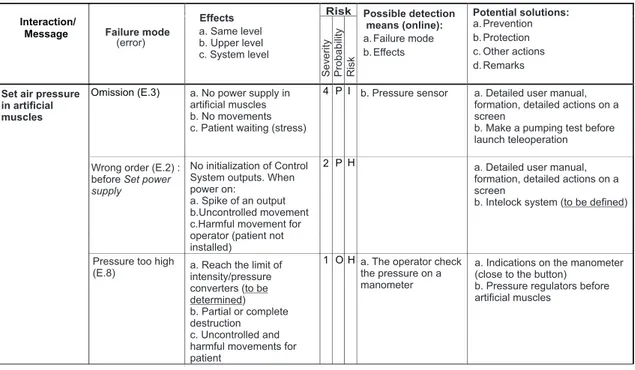
Specific errors of an interaction are instanced from our error models. Those error instances are integrated in tables of an FMECA analysis in the column "Failure modes". For instance, we consider the message Set air pressure in artificial muscles from figure 3. As shown in figure 5, we identify three failure modes from error models (the number has been reduced to present this example).
In order to determine other columns data, we have to refine TER Control System. Static and dynamic di-agrams are needed to understand and identify possible effects. For the system static view, this is represented by the class diagram on figure 6. This diagram repre-sents the slave control system of the TER project. The
slave robot, manipulating the probe, is actuated by ar-tificial muscles. This diagram which is close to more common block diagram, is an UML class diagram with annotations as proposed in [25]. This diagram is used to determine effects of the failure modes on actors (col-umn "Effects"). The risk calculation first requires an estimation of harm severity (effect at the system level). We proposed to use a scale with five levels: negligi-ble (5), minor (4), major (3), sever (2), catastrophic (1). A more complete description of those levels is done in [24]. The second data for risk estimation is the probability of the harm. In case of the FMECA it is more common to estimate the probability of the fail-ure mode leading to the harm. Actually, a quantitative evaluation of the probability of occurrence of a speci-fied human error is impossible to perform. In our case we did not base this on human performance models or on experimental data. And we only do a qualitative es-timation with different levels of probability of occur-rence: frequent, probable, occasional, rare, impossible. This point has to be developed, and relied to our type of errors. We have determined types of human errors that can appear in a human-machine interaction, but the causes are not integrated. Other columns propose so-lutions for risk reduction (mainly prevention and pro-tection). This technique also points to important details for safety that must be determined, such as maximum limit of air supply for converters.
4
Conclusion
The aim of the proposed approach is twofold: to man-age the growing complexity of human robot interac-tions and to handle safety requirements. First, we iden-tify and model human robot interactions with UML. This process leads to a more consistent task allocation, and produces models used is subsequent development steps. Moreover the models are understandable with various actors of the development process (developers and doctors for instance). Second, we have presented interaction error models defined on the UML notation. Our presentation focussed on the message which is one of the features of the UML sequence diagram used to express interactions. We provided an interpretation of each error model in term of erroneous collaborations between actors and the robotic system. As an illustra-tion, error models have been instanced and integrated in an FMECA.
This approach was applied successfully to the de-velopment of a first prototype of a medical robot for tele-echography. Others studies should be performed to complete and validate this work. Moreover a tool must be developed to automatically check the numer-ous errors potentially present in a model.
Interaction/ Message
Omission (E.3) 4 P I
2 P H
1 O H Set air pressure
in artificial muscles
Wrong order (E.2) : before Set power
supply Risk Failure mode (error) Effects a. Same level b. c. System level Upper level Risk Possible detection means (online): a. Failure mode b. Effects Potential solutions: a. Prevention b. Protection c. Other actions d. Remarks Probability Severity
Pressure too high (E.8)
b. Pressure sensor
No initialization of Control System outputs. When power on:
a. Spike of an output b.Uncontrolled movement c.Harmful movement for operator (patient not installed)
a. Reach the limit of intensity/pressure converters ( ) b. Partial or complete destruction c. Uncontrolled and harmful movements for patient
to be determined
a. Detailed user manual, formation, detailed actions on a screen
b. Make a pumping test before launch teleoperation a. Detailed user manual, formation, detailed actions on a screen
b. Intelock system (to be defined) a. No supply in
artificial muscles b. No movements c. Patient waiting (stress)
power
a. The operator check the pressure on a manometer
a. Indications on the manometer (close to the button)
b. Pressure regulators before artificial muscles
Figure 5 : Example of a table of FMECA for the message "Set air pressure in artificial muscles"
Artificial Muscle <<external device>> Robot Patient Probe <<external device>> Master Site I/P Convertor <<external output device>>
Position Sensor <<external input device>>
Force Sensor <<external input device>> Control System
Operator
1
Provide kinetic energy
Transmit movements Moves on 1 1 1 1 Provide pressure 1 1 1 Interact with 14 1 14 1
Send a pressure command
Provide position 1 1 1 1 Provide force Interact with Transmit movements
References
[1] B.S. Dhillon. Robot reliability and safety. Springer-Verlag, 1991.
[2] ISO/IEC Guide 51. Safety aspects - Guidelines for their inclusion in standards. International Or-ganization for Standardization, 1999.
[3] ISO/IEC Guide 73. Risk management - Vocab-ulary - Guidelines for use in standards. Interna-tional Organization for Standardization, 2002. [4] Food and Drug Administration. Medical device
use-safety: incorporating human factors engineer-ing into risk management. Technical report, U.S. Departement of Health and Human Service, 2000. [5] HSE. Proposed framework for addressing hu-man factors in IEC 61508. Technical Report 373/2001, Health and Safety Executive, UK, 2001. http://www.hse.gov.uk.
[6] J. Guiochet and A. Vilchis. Safety analysis of a medical robot for tele-echography. In Proc. of the 2nd
IARP IEEE/RAS joint workshop on Techni-cal Challenge for Dependable Robots in Human Environments, Toulouse, France, pages 217–227, October 2002.
[7] J. Guiochet, B. Tondu, and C. Baron. Integration of UML in human factors analysis for safety of a medical robot for tele-echography. In Proc. of the IEEE/RSJ International Conference on Intelligent Robots and Systems (IROS03), pages 3212–3218. IEEE Publisher, October 2003.
[8] J. Guiochet, G. Motet, C. Baron, and G. Boy. Toward a humancentered UML for risk analysis -application to a medical robot. In WCC 18th IFIP World Computer Congress, Human Error Safety and System Development, August 2004.
[9] I. Jacobson. Object-oriented software
engineer-ing: a use case driven approach.
Addison-Wesley, 1992.
[10] H.E. Eriksson and M. Penker. Business modeling with UML: business patterns at work. John Wiley and Sons, Inc., 2000.
[11] G. Booch, J. Rumbaugh, and I. Jacobson. Unified Modeling Language Users Guide. Addison Wes-ley Longman, 1999.
[12] A. Cockburn. Structuring uses cases with goals. Journal of Object Oriented Programming, 8(6/7), 2000.
[13] G. Hannaman and A. Spurgin. Systematic human action reliability procedure (SHARP). Project 2170-3, Interim report EPRI NP-3583, NUS Cor-poration, San Diego, CA, US, 1984.
[14] A. Swain and H. Guttmann. Handbook on hu-man reliability analysis with emphasis on nu-clear power plant application. NUREG/CR-1278 SAND 80-0200 RX, Nuclear Regulatory Com-mission, Washington, US, 1983.
[15] C. Kelly, P. Enterkin, and P. Goillau. Human fac-tors integration in future ATM systems - methods and tools. Technical Report HRS/HSP-003-REP-03, Eurocontrol, European Organisation for the Safety of Air Navigation, 2000.
[16] J. Reason. Human Error. Cambridge University Press, 1990.
[17] N.G. Leveson. Safeware - System safety and com-puters. Addison-Wesley, 1995.
[18] P. Wright, B. Fields, and M. Harrison. Deriving human-error tolerance requirements from tasks. IEEE International Conference on Requirements Engineering (ICRE’94), 1:462–467, 1994. [19] MIL-STD-1629A. Procedures for performing a
Failure Mode, Effects and Criticality Analysis. Military Standard, 1980.
[20] OMG. Unified Modeling Language Specification v1.5. Technical Report formal/03-03-01, Object Management Group, March 2003.
[21] OMG. Unified Modeling Language Specifica-tion v1.4. Technical report, Object Management Group, September 2001.
[22] OMG. 2nd revised submission to OMG RFP ad/00-09-02 - Unified Modeling Language : Su-perstructure - version 2.0. Technical Report ad/2003-01-02, Object Management Group, Jan-uary 2003.
[23] J. Guiochet and C. Baron. UML based FMECA in risk analysis. In Proc. of the European Simulation and Modelling Conference ESMc2003, Naples, Italy, October 2003.
[24] J. Guiochet. Safety management of service robot systems - UML approach based on system risk analysis (in french). PhD thesis, Institut National des Sciences Appliquées de Toulouse, 2003. [25] H. Gomaa. Designing concurrent, distributed,
and real-time applications with UML. Object Technology Series. Addison-Wesley, 2000.