Science Arts & Métiers (SAM)
is an open access repository that collects the work of Arts et Métiers Institute of
Technology researchers and makes it freely available over the web where possible.
This is an author-deposited version published in: https://sam.ensam.eu
Handle ID: .http://hdl.handle.net/10985/10009
To cite this version :
Brian LESTER, Theocaris BAXEVANIS, Yves CHEMISKY, Dimitris LAGOUDAS - Review and Perspectives: Shape Memory Alloy Composite Systems - ACTA MECHANICA p.60p. - 2015
Any correspondence concerning this service should be sent to the repository Administrator : [email protected]
Brian T. Lester · Theocharis Baxevanis · Yves Chemisky · Dimitris C. Lagoudas
Review and Perspectives: Shape Memory Alloy
Composite Systems
Received: date / Accepted: date
Abstract Following their discovery in the early 60’s, there has been a continuous quest for ways to take advantage of the extraordinary properties of shape memory alloys (SMAs). These intermetallic alloys can be extremely compliant while retaining the strength of metals and can convert thermal energy to mechanical work. The unique properties of SMAs result from a reversible difussionless solid-to-solid phase transformation from austenite to martensite. The integration of SMAs into composite structures has resulted in many benefits, which include actuation, vibration control, damping, sensing, and self-healing. However, despite substantial research in this area, a comparable adoption of SMA composites by industry has not yet been realized. This discrepancy between academic research and commercial interest is largely associated with the material complexity that includes strong thermomechanical coupling, large inelastic deformations, and variable thermoelastic properties. Nonetheless, as SMAs are becoming increasingly accepted in engineering applications, a similar trend for SMA composites is expected in aerospace, automotive, and energy conversion and storage related applications. In an effort to aid in this endeavor, a comprehensive overview of advances with regard to SMA composites and devices utilizing them is pursued in this paper. Emphasis is placed on identifying the characteristic responses and properties of these material systems as well as on comparing the various modeling methodologies for describing their response. Furthermore, the paper concludes with a discussion of future research efforts that may have the greatest impact on promoting the development of SMA composites and their implementation in multifunctional structures.
Keywords Shape Memory Alloys · Composites · Micromechanics · Multiscale Modeling · Finite Element Analysis
B. T. Lester
Department of Aerospace Engineering, Texas A&M University, College Station, TX 77843–3141, USA E-mail: [email protected]
T. Baxevanis
Department of Aerospace Engineering, Texas A&M University, College Station, TX 77843–3141, USA E-mail: [email protected]
Y .Chemisky
Arts et M´etiers ParisTech, LEM3-UMR 7239 CNRS, 4 Rue Augustin Fresnel, 57078 Metz, France E-mail: [email protected]
D. C. Lagoudas
Department of Aerospace Engineering and Department of Materials Science & Engineering, Texas A&M Uni-versity, College Station, TX 77843–3141, USA
2
1 Introduction
Shape memory alloys (SMAs) are a unique class of intermetallic materials capable of undergoing a re-versible solid-to-solid phase transformation via thermal and/or mechanical loadings which may result in large recoverable, inelastic strains of∼ 1 − 8% [232,325]. Specifically, at high temperature and low stress the material structure is that of a high-symmetry (cubic) austenitic phase while at low tempera-ture and high stresses a lower symmetry (typically orthorhombic or monoclinic) martensitic structempera-ture is observed. Two key behaviors of SMAs result from this transformation – the shape memory effect (SME) and pseudoelasticity. The former refers to the ability of the material to recover large, seemingly permanent strains via heating from a deformed shape in martensite to a remembered, austenitic one while the latter is associated with SMAs being able to undergo large, hysteretic stress–strain excur-sions without any permanent deformations at a sufficiently high temperature [232]. Because of these exciting responses, SMAs have been increasingly investigated for application in roles such as actua-tors [46], couplers, and vibration dampeners [75], in the aerospace [172,74], civil [326,406,115], and petroleum [4] industries as well as in MEMS devices [45]. Furthermore, NiTi (the most common SMA) is biocompatible leading to the application of SMAs in biomedical devices such as stents [286,118,302] and implants [31, 123].
Since their discovery [72], SMAs have been increasingly accepted as an engineering solution to a wide variety of problems. As such, multiple research efforts have focused on expanding their po-tential applications [410] by exploring ways of taking advantage of or even improving their unique performance-related characteristics. To accomplish this goal, Ashby and Br´echet [16] identified two possible approaches: (i) the development of new alloys and material systems or (ii) the creation of hybrid materials that combine the characteristics of existing materials. Efforts towards the former have resulted in the creation of high-temperature SMAs (HTSMA) [285,138], magnetic shape mem-ory alloys (MSMAs) [211, 359], and shape memmem-ory polymers (SMPs) [251,373]. The latter possibility, however, holds more excitement with respect to SMAs. Specifically, by combining one (or more) SMA phases with other constituents, novel material systems with both specific effective thermoelastic and transformation behaviors may be created. Such a concept incorporates materials with distinct phases including using SMA as either reinforcement or matrix and porous media. The former will be referred to (collectively) as SMA composites and efforts into this area started in the late 1980’s, when Rogers and Robertshaw [383] first embedded NiTiNOL wires in a laminated polymer matrix composite (PMC). In this initial investigation, Rogers and Robershaw [383] first introduced the term SMA composite and classified this material as an adaptive material that they defined as, “... a composite material that contains shape memory alloy fibers (or films) in such a way that the material can be stiffened or controlled by the addition of heat.” As will be seen in the remainder of this paper, the SMA com-posite class of materials has greatly expanded in terms of microstructure and application versus that original definition. Examples are shown in Fig. 1 in which micrographs of polymer, metal, and ceramic matrix composites and porous specimens are presented. The indicated composites exhibit a variety of reinforcement types (e.g., fiber, particulate, controlled channel networks) and have been considered for a wide range of purposes. A complete listing of composites that have been manufactured and used for either experimental or application purposes is presented in a later section for composites with the SMA playing the role of either the reinforcement or matrix.
Initial efforts into SMA composites focused on utilizing the SME of SMA wires in two ways – active property tuning and active strain energy tuning (commonly referred to in the literature as APT and ASET, respectively) [383, 382,267, 379]. Active property tuning refers to transformation of undeformed SMA wires from their martensitic state to the austenitic one to take advantage of the corresponding increase in elastic modulus which can be quite useful in vibration, damping, and structural control. For active strain energy tuning, initially elongated wires are heated back to their remembered, austenitic shape. The induced contraction of the wires leads to large internal stresses (and strain energy) that, in addition to the change in modulus, can provide even greater control over vibration, damping, or other structural characteristics [380, 268, 381,394,42,43,41,377,378,126]. Baz and Ro [44] extended this con-cept by accounting for the inherit energy dissipation of martensitic transformation in conjunction with changes in composite stiffness to achieve optimal vibration control over a broad frequency spectrum. The SME was further used to increase the effective yield strength in SMA/metal matrix composites due to the internal forces associated with thermal recovery as initially proposed by Yamada et al. [460] and demonstrated by Armstrong and Kino [8]. Paine et al. [332] also used the SME with a NiTi reinforced
3
tions of the aforementioned parameters to their functional perfor-mance must be synergistic, which can be a significant challenge. This is because the functional attributes of their performance con-tributions sometimes lead to significant conflicting consequences, which compromise the performance of the components, as well as undesirable ‘side effects’. For example, an adaptive beam embedded with prestrained one-way SMA wires was expected nominally to show substantial deflection with a reasonable actua-tion rate, once energised through electric heating. Intuitively, it seemed desirable for the host composite beam to (a) have a large amount of highly prestrained wires embedded with a sufficiently large eccentricity to deliver sufficient bending moment and then substantial deflection; (b) have a relatively moderate flexural rigid-ity against which the beam bending induced by the not-so-high le-vel of bending moment would have to overcome; and (c) be actuated by a high level of electric current to achieve desired actu-ation responsive rate. However, these attributes led immediately to several difficulties as they were conflicting requirements. Although nitinol wires had a recovery strain of up to 8%, the high level of prestraining could lead to their rapid ageing during
mul-ti-cycle actuations [12]. The thickness of the composite host
re-mained the most difficult parameter to reconcile. One the one hand, a relatively large thickness offered a greater eccentricity and a relatively large flexural rigidity. The latter was required not only to return the actuated beam to its original position but also to prestrain the embedded wire actuators again for the next cycle. On the other hand, the greater flexural rigidity of the beam could become a greater obstacle for the host to overcome to achieve the desired bending. Moreover, as phase transformations were hysteretic and could thus release latent heat, a high level of applied current, desirable and necessary for a high actuation re-sponse rate, could result in heat damage in the composite host
[12,13], which could in turn affect the wire actuation capability for subsequent cycles. In addition, embedding too many SMA wires in the host could also adversely affect the long-term
through-the-thickness mechanical properties of the host structures[14].
Although the literature abounds with individual endeavours of using SMAs for the shape control of smart adaptive structures as
discussed in[1–9], a synergistic set of the performance attributes
from the aforementioned parameters seemed clearly application specific involving inevitable compromises. In particular, the exper-imental thermomechanical behaviour of embedded SMA actuators, underpinning and justifying those compromises, has not been understood. To this end, it is of paramount importance to develop a good understanding of actuation characteristics of SMA-based adaptive composite beams in terms of performance bounds of the aforementioned important parameters. This experimental study aims on the examination of actuation characteristics of E-glass/epoxy and carbon/epoxy laminate beams embedded with nitinol wire actuators. Its focus will be on the manufacturability and actuation repeatability of adaptive composite beams and the effects of beam length and applied current level on their actuation characteristics. Information generated and experience gained will be channelled into the subsequent examination of their multi-cy-cling characteristics and related heat damage.
2. Design considerations
The design and manufacture of adaptive composite beams re-quire considerations and selection of a significant number of per-formance and actuation parameters. These include SMA wire material, wire cross-sectional profile and dimension, prestrain le-vel, volume fraction and through-the-thickness location, host com-posite material and lay-up, a level of applied current, and beam dimensions for the given performance requirements in terms of bending strain. A comprehensive experimental investigation of
treating all these parameters as equal variables will be prohibi-tively expensive. Thus the current study has focused on the varia-tion of just four selected parameters, namely, composite host material, applied current level, beam length and actuation cycle.
There are three major SMAs such as Cu–Zn–Al, Cu–Ni–Al and binary Ni–Ti (nitinol) used for adaptive structural applications
[15]. The latter was selected here because of its greater strain
recovery capacity, excellent corrosion resistance, stable transfor-mation temperatures with a relatively high electrical resistance and compatibility with cure temperatures of the present host com-posites. Current binary nitinol wires from Memory-Metalle GmbH had a nickel content of 55.3%. Its transformation temperatures were determined from thermographs generated using a differential
scanning calorimetre (DSC). They are 16!C for Mf, 21!C for Ms,
47!C for As, and 55!C for Af. While a Young’s modulus of
51.8 GPa was obtained from an austenitic stress–strain response
performed at 80!C, a martensitic Young’s modulus of 26.5 GPa
was obtained with a yield strength of 268 MPa at 1.96%. Nitinol wires of two different diameters (0.25 mm and 0.51 mm) were evaluated for their strain recovery capability as well as their actu-ation performance. Although the thinner wire in the construction of smart beams caused the less local distortion to the composite hosts (even when embedded in a unfavourable manner with a very
small wire-to-wire spacing), as shown inFig. 1, the thicker wire of
0.51 mm diameter was selected for its greater potential of recovery
force for a constant wire volume fraction[16]. It was understood
that the greater energy density via the larger diameter wires could be achieved at the expense of slower heating and cooling rates due to their increased mass and need for thermal transfer.
Two different composite host materials, carbon/epoxy and E-glass/epoxy, were evaluated. Although a 32-ply thick quasi-isotro-pic carbon/epoxy laminate would provide a more useful flexural rigidity for the host beam as well as a larger eccentricity, its flex-ural rigidity could be much more difficult to overcome. Thus, a 16-ply carbon/epoxy laminate (T700/LTM45-EL) was used as the
host with a stacking sequence of (45!/90!/!45!/0!/SMA/0!/!45!/
90!/45!/45!/90!/!45!/0!/0!/!45!/90!/45!) with a nominal ply
thickness of 0.128 mm. The flexural modulus of the intact host laminate beams was measured to be about 47 GPa. The flexural modulus of the smart beams with the wires being in the martens-itic condition was reduced to about 44 GPa. One through-the-thickness quarter location was selected to provide a wire eccentric-ity, although it was very desirable to have the wires embedded as far away from the mid-plane of the beams as possible. Since the wire diameter was about four times greater than the nominal ply thickness, two adjacent plies were oriented to 0! in the longitudi-nal direction of the beams so that the nitinol wires could partially sink in between them so as to minimise local distortion, as a
micro-graph inFig. 2shows. The local waviness in the micrograph is still
quite visible. Nevertheless, the previous experimental
investiga-Fig. 1. A micrograph of showing three embedded nitinol wires of 0.25 mm diameter within carbon/epoxy host.
G. Zhou, P. Lloyd / Composites Science and Technology 69 (2009) 2034–2041 2035
(a) Carbon/epoxy matrix reinforced with small diameter (0.25 mm) NiTi wires. Reprinted from [488] with per-mission from Elsevier.
equal to 1.875 for the first mode of vibration.q is the den-sity of composite beam. EI is the equivalent bending stiff-ness obtained from Eq.(1).
In order to predict the natural frequencies of the compos-ites as a function of temperature, the material constants of ER3 epoxy resin for different temperatures were obtained according to dynamic mechanical analysis (DMA) and the elastic modulus for the ER3 and the SMA as shown in
Table 2are used. 4. Results and discussion 4.1. Microstructural observation
The physical and mechanical properties of SMA/ER3 composites will largely depend on dispersion of SMA fillers into matrix. Fig. 4shows the surface observation of the SMA/ER3 composite layer using digital HF microscope. The images shown in Figs. 4(a) and (b) are the surfaces of the SMA/ER3 composite layers with 3.5 wt.% and 16.1 wt.% of SMA short fibers, respectively. Black and blank parts in the images represent SMA fillers and epoxy resin, respectively. The uniform distributions of SMA fibers were observed from these images although small aggregations exist occasionally in some regions.
4.2. Phase transformation of SMAs
The shape memory alloys undergo diffusionless martens-itic transformations on cooling beyond crmartens-itical
tempera-tures, Ms, which are dependent upon alloy composition, processing procedures and thermal/mechanical treatment condition.Fig. 5shows the differential scanning calorime-try (DSC) curves demonstrating the hysteresis of the phase transformation in used SMAs. The phase transition of SMAs occurs when the temperature increases. The begin-ning t(As) and end (Af) temperatures of the austenite trans-formation are from about 60 to 70!C. In the cooling process, R-phase transformation is involved at the temper-ature of approximate 60–42!C. The martensite phase transformation temperature occurs from about 21 to 2!C. 4.3. Flexural properties
Fig. 6shows Young’s modulus and fracture deflection in the developed two-layer laminated composites with dif-ferent SMA weight contents. The equivalent elasticity modulus in bending tests increased with the increment of SMA fiber weight content, while the fracture deflections decreased. These results suggest that the SMA short fiber composites show brittle fracture behavior for high SMA fiber content. Fig. 7 shows comparison of predicted and experimental results on elastic modulus for developed two-layer laminated composite beam. The theory calcula-tion of stiffness properties agrees reasonably with the experiment values. 0 3 6 9 12 15 3.5 5.1 16.1 27.4 0 1 2 3 4
SMA short fibers content, wt %
Young's modulus E, GPa
Fracture deflection, mm
Young’s modulus Fracture deflection
Fig. 6. Young’s modulus and fracture deflection for different SMA weight contents.
Fig. 4. Surface image of specimens (a) with 3.5 wt.% and (b) 16.1 wt.% of SMA fibers. -20 0 20 40 60 80 100 Cooling Heating A phase transformation M phase R phase transformation transformation Temperature Mf M s Rf Rs As Af
Fig. 5. Phase transformation of SMA wire (B0.2 mm).
504 Q.-Q. Ni et al. / Composite Structures 79 (2007) 501–507
equal to 1.875 for the first mode of vibration.q is the den-sity of composite beam. EI is the equivalent bending stiff-ness obtained from Eq.(1).
In order to predict the natural frequencies of the compos-ites as a function of temperature, the material constants of ER3 epoxy resin for different temperatures were obtained according to dynamic mechanical analysis (DMA) and the elastic modulus for the ER3 and the SMA as shown in
Table 2are used. 4. Results and discussion 4.1. Microstructural observation
The physical and mechanical properties of SMA/ER3 composites will largely depend on dispersion of SMA fillers into matrix. Fig. 4shows the surface observation of the SMA/ER3 composite layer using digital HF microscope. The images shown in Figs. 4(a) and (b) are the surfaces of the SMA/ER3 composite layers with 3.5 wt.% and 16.1 wt.% of SMA short fibers, respectively. Black and blank parts in the images represent SMA fillers and epoxy resin, respectively. The uniform distributions of SMA fibers were observed from these images although small aggregations exist occasionally in some regions.
4.2. Phase transformation of SMAs
The shape memory alloys undergo diffusionless martens-itic transformations on cooling beyond crmartens-itical
tempera-tures, Ms, which are dependent upon alloy composition, processing procedures and thermal/mechanical treatment condition.Fig. 5shows the differential scanning calorime-try (DSC) curves demonstrating the hysteresis of the phase transformation in used SMAs. The phase transition of SMAs occurs when the temperature increases. The begin-ning t(As) and end (Af) temperatures of the austenite trans-formation are from about 60 to 70!C. In the cooling process, R-phase transformation is involved at the temper-ature of approximate 60–42!C. The martensite phase transformation temperature occurs from about 21 to 2!C. 4.3. Flexural properties
Fig. 6 shows Young’s modulus and fracture deflection in the developed two-layer laminated composites with dif-ferent SMA weight contents. The equivalent elasticity modulus in bending tests increased with the increment of SMA fiber weight content, while the fracture deflections decreased. These results suggest that the SMA short fiber composites show brittle fracture behavior for high SMA fiber content. Fig. 7 shows comparison of predicted and experimental results on elastic modulus for developed two-layer laminated composite beam. The theory calcula-tion of stiffness properties agrees reasonably with the experiment values. 0 3 6 9 12 15 3.5 5.1 16.1 27.4 0 1 2 3 4
SMA short fibers content, wt %
Young's modulus E, GPa
Fracture deflection, mm
Young’s modulus Fracture deflection
Fig. 6. Young’s modulus and fracture deflection for different SMA weight contents.
Fig. 4. Surface image of specimens (a) with 3.5 wt.% and (b) 16.1 wt.% of SMA fibers. -20 0 20 40 60 80 100 Cooling Heating A phase transformation M phase R phase transformation transformation Temperature Mf M s Rf Rs As Af
Fig. 5. Phase transformation of SMA wire (B0.2 mm).
504 Q.-Q. Ni et al. / Composite Structures 79 (2007) 501–507
(b) ER3 epoxy resin matrix re-inforced with 16.1 wt%, dis-persed short (≈2 mm) NiTi fibers. Reprinted from [320] with permission from Elsevier.
The comparisons above indicate that B-1233-8 has the least
reaction and thus the most transformable NiTi (Section
3.5
).
How-ever, the relative density (83.3%) is low. In order to improve
densi-fication, the graphite die was replaced with a SiC die to reach higher
sintering pressures (i.e. 200 MPa and 300 MPa in this case).
Fig. 6
(a)
shows the relative density of NiTi/Ti
3
SiC
2
composites as a function
of the sintering pressure. The relative density increases from 83.3%,
to 89.1%, and to 96.3% as the sintering pressure increases from
100 MPa, to 200 MPa, and to 300 MPa.
Fig. 6
(b and c) shows that
the interfacial layer growth under higher pressure was negligible.
It suggests that, unlike sintering temperature and soaking time,
sintering pressure is not an influential parameter for reactions. In
other words, increasing sintering pressure not only improves
den-sification but also preserves transformable NiTi. The preserved
transformable NiTi was confirmed in DSC results (
Table 1
) where
percent of transformable NiTi was determined for all three cases.
3.4. Phase analyses and reaction mechanisms
The results presented up to this point indicate that the reaction
between NiTi and Ti
2
AlC or Ti
3
SiC
2
is a limiting factor in fabricating
the composites. Therefore, a combination of FE-SEM, EDS, and
Fig. 4. Back scattered SEM images of (a) A-1233-8, (b) A-1233-20, (c) A-1233-30, (d) A-1253-10, and (e) A-1273-3. The insets show lower magnification micrographs. Plots (f)
and (g) show the relative density and interface thickness of these composites. Dash lines were added to highlight the interfaces.
Fig. 5. Back scattered SEM images of (a) A-1233-20 and (b) B-1233-20. The insets show lower magnification micrographs. Dash lines were added to highlight the interfaces.
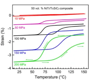
(c) NiTi − Ti3SiC2 compositepro-duced via spark plasma sintering. Reprinted from [187] with permis-sion from Elsevier.
was 114.3!C and 121.5 !C respectively. The martensitic transfor-mation start (Ms) and finish (Mf) temperature was 64.8!C and
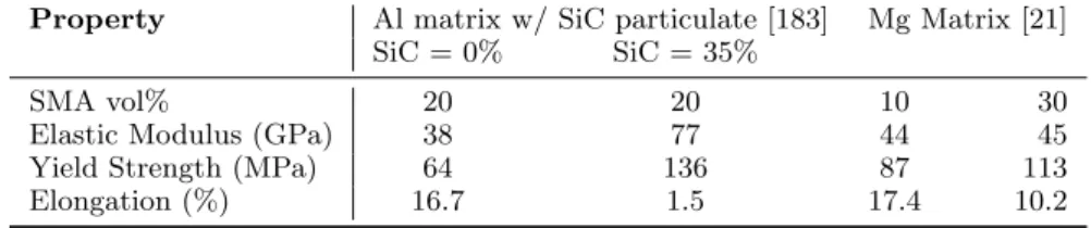
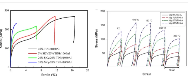
35.1!C respectively. It can be inferred that the TiNi alloy is in mar-tensitic phase at room temperature. The volume fraction of TiNi fibers was set approximately equal to 20%. While the SiC particu-late in the composite had four different volume fractions: 0%, 5%, 20% and 35%.
The aluminum metal matrix composite hybrid reinforced by SiC particulate and TiNi fiber was fabricated by pressure infiltration method in ambient air. The TiNi fibers were arrayed straight at a constant spacing for preventing contact. Pure Al power with the
average size of 5lm were mixed with SiC particulate in a ball mill for about 8 h, the rotary speed was 1550 rpm. No ball was used during mixing. After been mixed evenly, the mixed power was poured into the gap between the TiNi fibers. The fiber holder with mixed power was then placed in a mold into which molten pure Al was poured, followed by pressurization at 35 MPa. An anneal treat-ment was performed at 473 K for 30 min after the composites were fabricated.
An evaluation was performed by scanning electron microscope (SEM, Quanta 200FEG) with energy dispersive spectrometer (EDS) to observe the adhesion state and interfacial reaction of the com-posites. Mechanical properties of the composites were tested by rectangle specimens (width 10 mm and length 80 mm) using instron 5569 with tensile velocity of 1 ! 10"2mm s"1at room
temperature. The damping capacity of the composites was mea-sured using a dynamic mechanical analyzer (DMA Q800, TA) in the single-cantilever mode. The geometry of damping specimens was 1.5 mm ! 8 mm ! 35 mm (thickness ! width ! length). The damping tests were conducted at constant strain amplitude of 5 ! 10"5with a constant heating rate of 10!C min"1.
Fig. 1. Schematic diagram of the structure in the SiCp/TiNif/Al composite.
Table 1
Phase transformation temperatures of TiNi fiber.
Phase transformation points Temperature (!C)
Mf 35.1
Ms 64.8
As 114.3
Af 121.5
Fig. 2. Typical microstructure of composites: (a) 20%TiNif/Al composite, (b) 5%SiCp+ 20%TiNif/Al composite, (c) 20%SiCp+ 20%TiNif/Al composite, and (d) 35%SiCp+ 20%TiNif/
Al composite.
J. Hu et al. / Composites: Part B 66 (2014) 400–406 401
(d) Al matrix (reinforced with 5% SiC particles) composite re-inforced with long NiTi fibers. Reprinted from [183] with per-mission from Elsevier.
430 J.S. Juan, M.L. N´o / Materials Science and Engineering A 442 (2006) 429–432
Fig. 1. Optical micrograph of the metal matrix composite obtained by Nomarsky interferential contrast. The indium matrix surrounds Cu–Al–Ni powder particles, showing some surface relief from the martensite variants.
infiltrated at a pressure of 3 × 10⁵Pa.Fig. 1is an optical
micro-graph obtained by Nomarsky interferential contrast in a LEICA DMRXA optical microscope. It shows a general view of the microstructure of the composite, in which the indium matrix surrounds the Cu–Al–Ni alloy particles. The particles undergo the martensitic transformation after the production of the com-posite, as if the composite exhibits such a transformation. This fact is illustrated inFig. 2showing the martensitic transforma-tion cycle, measured by differential scanning calorimetry (DSC) in the original atomised powders, in comparison with the cycle measured in the composite. The transformation cycle of the
com-Fig. 2. Transformed volume fraction during martensitic transformation of the original Cu–Al–Ni powders, measured by DSC (rhombi), in comparison with those of the composite prepared from the same powders, evaluated by integrating the internal friction spectrum (circles).
posite has been obtained from the internal friction spectra during cooling and heating; the integrated area of the internal friction peak is proportional to the transformed volume fraction[11]. There is only a slight shift towards higher temperature, as well as a slight broadening of the transformation cycle of the com-posite. The shift in temperature is associated with the general evolution of the transformation cycle in Cu–Al–Ni during age-ing after quenchage-ing. The original powders were quenched, while the powders of the composite were aged at 190◦C for about 1 h.
The damping behaviour of the composite has been stud-ied by mechanical spectroscopy in a forced torsion pendulum, described elsewhere[12], measuring tan φ; φ is the lag angle between the strain and the stress, and tan φ represents the dis-sipated energy by unit of volume and is called internal friction. Internal friction has been measured as a function of tempera-ture at various frequencies between 3 and 0.01 Hz and at various strain amplitudes. In all cases the spectra as a function of tem-perature have been measured under linear heating–cooling at a rate of 60 K/h.
3. Results and discussion
InFig. 3, we present the internal friction spectra and the associated modulus variation of the composite during cooling and heating. We show the results for three frequencies, 3 Hz (Fig. 3a), 0.3 Hz (Fig. 3b) and 0.03 Hz (Fig. 3c), all with a strain amplitude of ε = 10−5. In all the cases an internal
fric-tion peak appears during cooling, which is associated with the forward martensitic transformation, and another during heating, which is associated with the reverse martensitic transformation. Both peaks are accompanied by a fall in the modulus, which is linked to the softening of the elastic constants, undergone by the Cu–Al–Ni particles during the martensitic transformation. An increasing background is observed, which is due to the metallic matrix of indium, whose melting point is at 429.6 K. Atten-tion has to be paid to the different levels of internal fricAtten-tion at the three frequencies: internal friction increases with decreas-ing frequency, as predicted theoretically[11,13]. InFig. 4the internal friction spectrum during the forward transformation of the composite is compared with that of the bulk Cu–Al–Ni alloy prepared by powder metallurgy after compaction by hot isostatic pressing and hot rolling[7]. Both spectra have been measured in the same experimental conditions: at a frequency of 1 Hz, a strain amplitude of ε = 10−5and a cooling rate of 60 K/h.
The bulk material exhibits the transformation at higher tem-perature, owing to the internal stresses created during the powder metallurgy processing. Second, the composite exhibits a broader transformation peak and higher internal friction background. The broadening of the peak in the composite can be understood if we consider that, during the transformation of the Cu–Al–Ni particles, some surface relief should appear as a consequence of the transformation shearing. However, the indium matrix sur-rounding the particles will oppose to the relief modifications and will perform some stress against the shearing, which is responsi-ble for the delay in the transformation of the particles. Besides, when the shearing relief due to the martensite variants finally appears, it will produce some local plastic deformation on the (e) Indium matrix composite with
CuAlNi SMA particle reinforcement producing a high damping material. Reprinted from [391] with permis-sion from Elsevier.
and at heating/cooling rates of 5 K min–1. Two tempera-ture cycles ranged from !60 to 170 !C and phase transfor-mation data were then obtained from the second cycle. The areas under the peaks were used to calculate the enthalpies. The intercepts between the baselines and the tangents at the inflection points of the peaks were taken as the transforma-tion temperatures: As, Ap, and Afrefer to austenitestart,
-peak, and -finish temperatures, and Ms, Mp, and Mfrefer
to martensite-start, -peak, and -finish temperatures. 2.4. Mechanical properties characterization
The mechanical properties of the specimens were assessed through compression testing on a screw-driven load frame. Strain was measured by an extensometer
attached to the sample up to "5%, and by cross-head dis-placement corrected for machine compliance at higher strains. An alignment cage was used to ensure parallelism of all components. The compression samples were pol-ished with 600lm grit sand paper to remove surface oxi-des remaining from the machining process. The specimen then underwent the following heat treatment: (i) annealing for 15 min at 130!C in air; (ii) air cooling to room tem-perature with subsequent 20 min hold; (iii) quenching in liquid nitrogen and 3 min hold; and (iv) warming to room temperature and 20 min hold. This ensured that all sam-ples had a martensitic microstructure during compression testing, which was performed at room temperature.
Three types of compressive tests were performed. For each test, a previously untested sample was used. First, to
Fig. 2. Scanning electron micrographs of samples (a) LP90[51], (b) LP45, (c) LP0, (d) HP90[51], and (e) HP0. The inset images show the channel orientation (indicated by the dotted line) with respect to the compression direction (indicated by the arrows). (f) Magnified images of the channel intersections in samples LP and HP.
A.J. Neurohr, D.C. Dunand / Acta Materialia 59 (2011) 4616–4630 4619
(f) Porous NiTi specimen with con-trolled 2D micro channels produced by via sacrificial steel meshes. Reprinted from [315] with permission from Else-vier.
Fig. 1: Examples of different SMA reinforced polymer (a,b), ceramic (c), and metal (d-e) matrix composite and porous (f) systems that have recently been developed.
polymer matrix system to relieve peak tensile stresses in pressure vessels. Other topics of the early investigations included improved impact damage resistance via the dissipative nature of the hysteric response of pseudoelastic SMAs [329, 331], enhancement of critical buckling loadings and improvement in the post-buckling response [376]. Shape memory alloy reinforced composites were also considered as promising candidates for morphing structures. Composite actuators in the form of beams and rods were first analyzed by Chaudhry and Rogers [83] and Lagoudas and Tadjbakhsh [241,242], respectively, and subsequent efforts focused on characterizing the actuation response of SMA composites soon fol-lowed [449,33,60] (including SMA-piezoelectric systems [235,236]). Over the years, actuators comprised of SMA composites have been extended from simple engineering configurations (e.g., rods and beams) to complex structures. Specifically, in the aerospace community, adaptive jet-engine chevrons [426, 170], variable twist UAV propellor rotors [339,340], and morphing wings [401] have all been devel-oped. Similar principles have also been combined with origami concepts to create self-folding SMA composites capable of attaining a variety of configurations simply by changing the applied thermal loading [349,350]. Recent interest in bio-inspired applications has also led to a number of biomimetic robots. The motion of jellyfish [402, 433, 434] and turtles [221] (Fig. 2b) have been studied and used as a basis to develop SMA composite driven propulsive, aquatic machines. Locomotive devices based on inchworm movement has been used to create land-based robots [442]. Additional studies have also looked at applications beyond morphing structures including safety health monitoring devices (e.g., [355]). Thermally induced recovery loads have also been considered to improve self-healing [224] in polymers and damage suppression and toughening of concrete [264] (Fig. 2c).
4
Smart Mater. Struct.22 (2013) 125007 R Wu et al
Figure 1. Phase change temperature curve of SMA wire.
Figure 2. Concept diagrams of woven type SSC beam.
energy [21–31]. Therefore, a study of a new kind of morphing
structure is necessary to solve the problems mentioned above. In this research a new kind of smart structure, named a woven type smart soft composite (SSC) beam, is introduced, which can morph and maintain its deformed shape with no additional energy. The performance characteristics of the actuator were experimentally evaluated. Using a laser displacement sensor, repeatability, maximum deformation and retaining of position after stopping the flow of the current into the specimen were measured. To evaluate the blocking force of the specimen, a dynamometer (Kistler) was used as a sensing device. Finally, to assess the effect of SMA
Figure 3. Cross sectional image of woven type SSC beam: deformation generated by eccentricity.
cooling time on the magnitude of the maximum tip deflection, experiments were conducted with different activation intervals of embedded SMA wires.
2. Materials
The woven type SSC beam was fabricated using commercial SMA wires (Flexinol, Dynalloy, Inc.) with a diameter of 200 µm, glass fiber (KN2100 type, KPI Co., Ltd) and PDMS (Sylgard 184, Dow corning) as a matrix. The woven structure was made by weaving the SMA wires as the warp thread and the glass fibers as the weft thread. To measure the thermal properties of the SMA wires, the phase change temperature was captured by differential scanning calorimetry (DSC-Q100, TA Instruments) following the international standard (F2004-ASTM). Through the test, each transformation temperature was measured (austenite start temperature (As): 56.08 C, austenite finish temperature (Af): 72.63 C, martensite start temperature (Ms): 40.35 C and
martensite finish temperature (Mf): 31.52 C) (figure1).
As a weft thread, glass fibers which have a nonconductive behavior were selected for pairing with SMA wires in the woven structure, because SMA wires are the current path for actuating the whole structure. The thickness and width of the glass fiber are 0.21 mm and 1.5 mm respectively. PDMS, a soft polymeric material, was used as the matrix of the structure. It is easy to fill a mold because it is a viscous liquid before hardening. It is also fit to be the host part of the composite
Figure 4. Fabrication process of woven type SSC beam. 2
(a) Polymer matrix composite reforced with smart SMA weave in in-sert. SMA wires are used as warp fibers while carbon fibers take the weft position thereby improving shape re-tention possibilities. c IOP Publish-ing. Reproduced from [453] by permis-sion of IOP Publishing. All rights re-served.
Smart Mater. Struct.22 (2013) 014007 H-J Kim et al
Figure 15. Assembled turtle-like swimming robot. was 1300 mA, and the robot was manually controlled with a
switching circuit. The robot traveled a distance of 180 mm
in 8 s, resulting in an average speed of 22.5 mm s 1.
To determine the maximum speed in a single cycle of the swimming sequence, recorded video was analyzed. The
maximum speed in a single cycle was around 40 mm s 1
(36 mm in 0.9 s). Figure 16shows captured images of
the turtle-like robot during the swimming experiment. The end-edge twisting angle of flipper was 29 and end-edge deflection was 55 mm at the end of each stroke sequence.
5. Conclusion
To develop a biomimetic AUV, mimicking the soft-morphing deformation of a marine animal’s movement is an important issue. In particular, to mimic the flapping motions of a marine turtle for effective long-distance travel, a novel actuating mechanism should be used in place of conventional actuators that require many degrees of freedom. In this research, a SSC structure was employed to develop a turtle-like swimming robot. A SSC structure is advantageous for mimicking the smooth, soft motions of living creatures, such as the flapping of marine turtles. It also can be helpful for realizing simple, lightweight AUVs.
In preliminary experiments on the behavior of the SSC structure, a combination of orientations of filaments of the scaffold structure and SMA wires (relative to the longitudinal direction of the actuators) was regarded as the principal parameter for designing anisotropic laminates and obtaining bending and twisting deformation. To evaluate the ability of soft-morphing structures to bend and twist, cross-ply and angled-ply actuators and angled SMA wires were fabricated, and actuation experiments were conducted. With the center-aligned and 0 SMA wires, the [0/90/0] and [90/0/90] scaffold actuators exhibited bending deformation only. However, twisting with bending was obtained by using angled plies in the laminate. Angled SMA wires also exhibited twisting deformation by composing an anisotropic layer in the active component. The actuation response evaluations, carried out in air and water, showed that the energy efficiency increased with the applied current due to decreasing heat loss during actuation.
Figure 16. Captured image of the swimming experiment of the second version.
Based on the experimental behavior of the SSC structure, a turtle-like swimming robot was developed. The fore-flippers of the robot were designed to imitate the
9
Smart Mater. Struct.22 (2013) 014007 H-J Kim et al
Figure 15. Assembled turtle-like swimming robot. was 1300 mA, and the robot was manually controlled with a switching circuit. The robot traveled a distance of 180 mm in 8 s, resulting in an average speed of 22.5 mm s1. To determine the maximum speed in a single cycle of the swimming sequence, recorded video was analyzed. The maximum speed in a single cycle was around 40 mm s1 (36 mm in 0.9 s). Figure16shows captured images of the turtle-like robot during the swimming experiment. The end-edge twisting angle of flipper was 29 and end-edge deflection was 55 mm at the end of each stroke sequence. 5. Conclusion
To develop a biomimetic AUV, mimicking the soft-morphing deformation of a marine animal’s movement is an important issue. In particular, to mimic the flapping motions of a marine turtle for effective long-distance travel, a novel actuating mechanism should be used in place of conventional actuators that require many degrees of freedom. In this research, a SSC structure was employed to develop a turtle-like swimming robot. A SSC structure is advantageous for mimicking the smooth, soft motions of living creatures, such as the flapping of marine turtles. It also can be helpful for realizing simple, lightweight AUVs.
In preliminary experiments on the behavior of the SSC structure, a combination of orientations of filaments of the scaffold structure and SMA wires (relative to the longitudinal direction of the actuators) was regarded as the principal parameter for designing anisotropic laminates and obtaining bending and twisting deformation. To evaluate the ability of soft-morphing structures to bend and twist, cross-ply and angled-ply actuators and angled SMA wires were fabricated, and actuation experiments were conducted. With the center-aligned and 0 SMA wires, the [0/90/0] and [90/0/90] scaffold actuators exhibited bending deformation only. However, twisting with bending was obtained by using angled plies in the laminate. Angled SMA wires also exhibited twisting deformation by composing an anisotropic layer in the active component. The actuation response evaluations, carried out in air and water, showed that the energy efficiency increased with the applied current due to decreasing heat loss during actuation.
Figure 16. Captured image of the swimming experiment of the second version.
Based on the experimental behavior of the SSC structure, a turtle-like swimming robot was developed. The fore-flippers of the robot were designed to imitate the 9
Smart Mater. Struct.22 (2013) 014007 H-J Kim et al
Figure 15. Assembled turtle-like swimming robot. was 1300 mA, and the robot was manually controlled with a
switching circuit. The robot traveled a distance of 180 mm
in 8 s, resulting in an average speed of 22.5 mm s 1.
To determine the maximum speed in a single cycle of the swimming sequence, recorded video was analyzed. The
maximum speed in a single cycle was around 40 mm s 1
(36 mm in 0.9 s). Figure 16 shows captured images of
the turtle-like robot during the swimming experiment. The end-edge twisting angle of flipper was 29 and end-edge deflection was 55 mm at the end of each stroke sequence.
5. Conclusion
To develop a biomimetic AUV, mimicking the soft-morphing deformation of a marine animal’s movement is an important issue. In particular, to mimic the flapping motions of a marine turtle for effective long-distance travel, a novel actuating mechanism should be used in place of conventional actuators that require many degrees of freedom. In this research, a SSC structure was employed to develop a turtle-like swimming robot. A SSC structure is advantageous for mimicking the smooth, soft motions of living creatures, such as the flapping of marine turtles. It also can be helpful for realizing simple, lightweight AUVs.
In preliminary experiments on the behavior of the SSC structure, a combination of orientations of filaments of the scaffold structure and SMA wires (relative to the longitudinal direction of the actuators) was regarded as the principal parameter for designing anisotropic laminates and obtaining bending and twisting deformation. To evaluate the ability of soft-morphing structures to bend and twist, cross-ply and angled-ply actuators and angled SMA wires were fabricated, and actuation experiments were conducted. With the center-aligned and 0 SMA wires, the [0/90/0] and [90/0/90] scaffold actuators exhibited bending deformation only. However, twisting with bending was obtained by using angled plies in the laminate. Angled SMA wires also exhibited twisting deformation by composing an anisotropic layer in the active component. The actuation response evaluations, carried out in air and water, showed that the energy efficiency increased with the applied current due to decreasing heat loss during actuation.
Figure 16. Captured image of the swimming experiment of the second version.
Based on the experimental behavior of the SSC structure, a turtle-like swimming robot was developed. The fore-flippers of the robot were designed to imitate the
9
(b) Bioinspired turtle robot con-structured using SMA compos-ites as actuators for motion. Top and bottom show the start and finish of a swimming test with the robot displayed in the in-sert. c IOP Publishing. Repro-duced from [221] by permission of IOP Publishing. All rights re-served.
dissipation capacity compared with other types of specimens,
especially during the earlier loading cycles. This was because
the concrete specimen has severely cracked during the 1st
cycle and thus only the SMA dissipated energy during
sub-sequent loading-unloading cycles. The SMA-ECC was the
only one among the four types of composite material systems,
which combines high energy dissipation capacity and
self-centering capacity.
3.6. Spatial strain (or damage) field measured by digital image correlation system
The DIC results were used to extract data on the midspan
deflection during cyclic loading, as reported in the previous
sections. They also provided additional insights on the strain
distribution and damage pattern along the specimen surface
during each loading and unloading cycle. For example,
figure
14
shows the spatial strain measured by DIC at the
peak displacement of the 7th loading cycle, and after
com-plete unloading of this cycle. Note that damage, such as
cracking, was measured as ‘smeared strain’ by DIC. The
results shown in figure
14
clearly indicated that the ECC and
SMA-ECC specimens exhibited distributed damage behavior
under loading rather than the localized cracking found in the
RC and SMA-RC specimens. Because of the ductile response
of ECC, it suppressed large localized cracks and thus
deformed more uniformly along the beam together with the
SMA reinforcement (figure
14
(a)). In contrast, the SMA-RC
specimen experienced early-localized fracture in the form of a
large crack, thus the concrete and SMA was not able to
deform compatibly. Similarly, the RC specimen exhibited a
few localized cracks in concrete, which led to debonding
between concrete and ductile steel reinforcement. After
unloading, localized cracking in the RC and SMA-RC
spe-cimens still existed, although the crack width in SMA-RC
was reduced due to the use of SMA strands (figure
14
(b)). For
the ECC specimen, the distributed damage was slightly
aba-ted upon unloading, as indicaaba-ted by the reduction in the
magnitude of concentrated strains (which represented regions
of microcracks). For the SMA-ECC specimen, there was a
significant recovery of distributed damage, as indicated by the
very low strain values along the tensile side of the beam.
Examined by a high-magnitude microscope, all the
micro-cracks were fully closed. The results obtained from DIC
(figure
14
(b)), combined with the direct measurement of crack
width and number recovery described in sections
3.1
–
3.4
,
clearly illustrated the damage self-repairing capacity of
SMA-ECC.
4. Conclusions
This study developed a novel SMA-ECC composite material
system and investigated its behavior under cyclic flexural
loading, compared with SMA-RC, RC and ECC. The
fol-lowing conclusions are reached:
• The SMA-ECC beams exhibited a combination of
extraordinary energy dissipation capacity, minimal
Figure 14.Spatial strain measured by DIC at (a) the peak displacement and (b) after unloading of the 7th cycle.
13
Smart Mater. Struct. 24 (2015) 025024 X Li et al
dissipation capacity compared with other types of specimens, especially during the earlier loading cycles. This was because the concrete specimen has severely cracked during the 1st cycle and thus only the SMA dissipated energy during sub-sequent loading-unloading cycles. The SMA-ECC was the only one among the four types of composite material systems, which combines high energy dissipation capacity and self-centering capacity.
3.6. Spatial strain (or damage) field measured by digital image correlation system
The DIC results were used to extract data on the midspan deflection during cyclic loading, as reported in the previous sections. They also provided additional insights on the strain distribution and damage pattern along the specimen surface during each loading and unloading cycle. For example,
figure14shows the spatial strain measured by DIC at the
peak displacement of the 7th loading cycle, and after com-plete unloading of this cycle. Note that damage, such as cracking, was measured as ‘smeared strain’ by DIC. The
results shown in figure14clearly indicated that the ECC and
SMA-ECC specimens exhibited distributed damage behavior under loading rather than the localized cracking found in the RC and SMA-RC specimens. Because of the ductile response of ECC, it suppressed large localized cracks and thus deformed more uniformly along the beam together with the
SMA reinforcement (figure14(a)). In contrast, the SMA-RC
specimen experienced early-localized fracture in the form of a large crack, thus the concrete and SMA was not able to
deform compatibly. Similarly, the RC specimen exhibited a few localized cracks in concrete, which led to debonding between concrete and ductile steel reinforcement. After unloading, localized cracking in the RC and SMA-RC spe-cimens still existed, although the crack width in SMA-RC
was reduced due to the use of SMA strands (figure14(b)). For
the ECC specimen, the distributed damage was slightly aba-ted upon unloading, as indicaaba-ted by the reduction in the magnitude of concentrated strains (which represented regions of microcracks). For the SMA-ECC specimen, there was a significant recovery of distributed damage, as indicated by the very low strain values along the tensile side of the beam. Examined by a high-magnitude microscope, all the micro-cracks were fully closed. The results obtained from DIC
(figure14(b)), combined with the direct measurement of crack
width and number recovery described in sections3.1–3.4,
clearly illustrated the damage self-repairing capacity of SMA-ECC.
4. Conclusions
This study developed a novel SMA-ECC composite material system and investigated its behavior under cyclic flexural loading, compared with SMA-RC, RC and ECC. The fol-lowing conclusions are reached:
• The SMA-ECC beams exhibited a combination of extraordinary energy dissipation capacity, minimal
Figure 14.Spatial strain measured by DIC at (a) the peak displacement and (b) after unloading of the 7th cycle.
13
Smart Mater. Struct. 24 (2015) 025024 X Li et al
W \o u t SMA W \ SMA
dissipation capacity compared with other types of specimens,
especially during the earlier loading cycles. This was because
the concrete specimen has severely cracked during the 1st
cycle and thus only the SMA dissipated energy during
sub-sequent loading-unloading cycles. The SMA-ECC was the
only one among the four types of composite material systems,
which combines high energy dissipation capacity and
self-centering capacity.
3.6. Spatial strain (or damage) field measured by digital image correlation system
The DIC results were used to extract data on the midspan
deflection during cyclic loading, as reported in the previous
sections. They also provided additional insights on the strain
distribution and damage pattern along the specimen surface
during each loading and unloading cycle. For example,
figure
14
shows the spatial strain measured by DIC at the
peak displacement of the 7th loading cycle, and after
com-plete unloading of this cycle. Note that damage, such as
cracking, was measured as ‘smeared strain’ by DIC. The
results shown in figure
14
clearly indicated that the ECC and
SMA-ECC specimens exhibited distributed damage behavior
under loading rather than the localized cracking found in the
RC and SMA-RC specimens. Because of the ductile response
of ECC, it suppressed large localized cracks and thus
deformed more uniformly along the beam together with the
SMA reinforcement (figure
14
(a)). In contrast, the SMA-RC
specimen experienced early-localized fracture in the form of a
large crack, thus the concrete and SMA was not able to
deform compatibly. Similarly, the RC specimen exhibited a
few localized cracks in concrete, which led to debonding
between concrete and ductile steel reinforcement. After
unloading, localized cracking in the RC and SMA-RC
spe-cimens still existed, although the crack width in SMA-RC
was reduced due to the use of SMA strands (figure
14
(b)). For
the ECC specimen, the distributed damage was slightly
aba-ted upon unloading, as indicaaba-ted by the reduction in the
magnitude of concentrated strains (which represented regions
of microcracks). For the SMA-ECC specimen, there was a
significant recovery of distributed damage, as indicated by the
very low strain values along the tensile side of the beam.
Examined by a high-magnitude microscope, all the
micro-cracks were fully closed. The results obtained from DIC
(figure
14
(b)), combined with the direct measurement of crack
width and number recovery described in sections
3.1
–
3.4
,
clearly illustrated the damage self-repairing capacity of
SMA-ECC.
4. Conclusions
This study developed a novel SMA-ECC composite material
system and investigated its behavior under cyclic flexural
loading, compared with SMA-RC, RC and ECC. The
fol-lowing conclusions are reached:
• The SMA-ECC beams exhibited a combination of
extraordinary energy dissipation capacity, minimal
Figure 14.Spatial strain measured by DIC at (a) the peak displacement and (b) after unloading of the 7th cycle.
13
Smart Mater. Struct. 24 (2015) 025024 X Li et al
(c) Digital image correlation results of engineering cementitious compos-ite (ECC) beams (508mm in length) with and without SMA reinforce-ment at the end of 7 loading cycles. Strain fields in the without speci-men (top) indicate the presence of microcracks which are greatly di-minished by SMA presence (bot-tom). IOP Publishing. Repro-c duced from [264] by permission of IOP Publishing. All rights reserved.
Fig. 2: Recent examples highlighting efforts investigating (a-b) SMA composite actuators and (b) damage recovery/healing via SMA reinforcement.
The development of these SMA composite applications has been enabled by extensive experimental efforts into the underlying mechanics. The influences and effects of large recovery strains associated with martensitic transformation were of particular interest. Such deformations were investigated with respect to processing of SMA/polymer composites, where normal cure cycles can induce recovery in the SMA, and interfaces to ensure sufficient strength to survive transformation. With respect to the former, Paine and Rogers [328] first studied the effect of processing temperatures on the nominal recov-ery stress in thermoplastic systems while Hebda et al. [175] investigated the impact of SMA properties and curing techniques and conditions on graphite/epoxy reinforced systems. With respect to the lat-ter, pull-out experiments were performed to study a variety of surface treatments and demonstrated the early capabilities of sand blasting and the importance of mechanical interactions on interfacial strength [327,205, 203]. Additionally, photoelastic experiments by Jonnalagadda and coworkers ex-plored load transfer in systems with embedded SMA wires [203] and ribbons [204] and demonstrated that increased adhesion lowers wire displacement while increasing interfacial stress and transformation fronts move towards the center, respectively. Given the strong thermomechanical coupling exhibited by SMAs (notably, the latent heat of transformation), the thermal transport in these composites was also investigated [174, 375]. Such studies into the underlying mechanics, along with application devel-opment, were substantially aided by various analytical [382,196,49], micromechanical [460,237,68,69], and finite element [174, 42, 237,240] modeling methodologies that were utilized to study these problems. Even with these initial and subsequent investigations, some of these first issues (e.g., interface damage and damage suppression) are still of interest for SMA composites – albeit for a larger set of material systems. For additional discussions of these early efforts, the interested reader is refered to the works of Paine and Rogers [330] and Wei et al. [448] as well as that of Birman [56] and Neuking et al. [314] who focused on some of the underlying mechanics issues and polymer matrix systems, respectively.
The present paper reviews and discusses the experimental and modeling advances on the manu-facture, characterization, and simulation of SMA composites and devices utilizing them. Towards this objective, it is organized as follows. First, a brief review on the bulk SMA responses is given in Section 2 to aid in subsequent discussions. Recent efforts in manufacturing, experimentation, and application development of SMA composite systems are reviewed in Section 3 while Section 4 presents various
efforts and approaches to model and analyze SMA composites. Finally, Section 5 discusses the current state of SMA composites with an eye towards topics that have not been addressed satisfactorily and concludes with a discussion of future research priorities that may strongly influence their development and applications.
2 Characteristic Bulk SMA responses
Since the discovery of NiTi as an SMA at the Naval Ordinance Laboratory (hence, NiTiNOL) in the early 60’s [72], SMAs have received great interest for their unique thermomechanical behavior – especially the aforementioned shape memory and pseudoelastic effects. A complete review of efforts investigating the metallurgical, crystallographic, and phenomenological issues associated with these responses is outside the scope of this work and the interested reader is referred to various texts [324, 232,325].
To aid in subsequent discussions, a brief review of the pertinent characteristics and behaviors of SMA transformation is presented. First, to describe when transformation occurs, transformation tem-peratures are typically utilized. Such temtem-peratures refer to those observed under zero macroscopic loading. Specifically, the martensitic start, Msand finish, Mf, temperatures denote the initiation and completion of forward (austenite to martensite) transformation, respectively, while the austenitic start, As, and finish, Af, are used for the initiation and end of reverse (martensite to austenite) transfor-mation. These temperatures may be readily determined from calorimetry measurements as forward and reverse transformation are accompanied by either the release or absorption of heat, respectively, that is conventionally referred to as the latent heat of transformation [400,122,364,304]. Due to the thermomechanical nature of the martensitic transformation, as the applied stress increases so do the transformation temperatures. This coupling may be observed on a stress–temperature phase diagram like that in Fig. 3a via the linear dependence of the various transformation temperatures. The slopes of these lines are denoted as CM and CA for forward and reverse transformation, respectively, and
are commonly referred to as stress-influence coefficients. Although linear lines in Fig. 3a, in multiaxial stress–temperature space these transformation limits form complex surfaces in three dimensions and are functions of loading path.
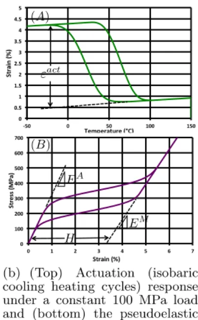
The shape memory and pseudoelastic responses may also be discussed via the phase diagram and are described in Fig. 3. First, upon cooling from the austenitic state the SMA will be in either a twinned or detwinned martensitic configuration depending on the applied macroscopic load. At lower loads, multiple martensitic variants may be present enabling the microstructure to self-accomodate via twinning. Macroscopically, the transformation from austenite to self-accomodated martensite produces no inelastic strain. If a sufficient load is applied during cooling or from the self-accomodated state, a detwinned structure is produced along with a corresponding macroscopic strain which may be recovered via heating and is referred to as the shape memory effect. The case of the heating–cooling cycle being performed under an applied load is commonly referred to as the actuation response and is indicated by path (A) in Fig. 3a. The corresponding strain–temperature response under a constant applied loading is presented in Fig. 3b. The inelastic strain developed as a result of this loading path is commonly referred to as the actuation strain and is denoted εactin Fig. 3b. Additionally, in the case of an isobaric
loading, the mechanically applied stress is referred to as the actuation stress and the product of the actuation stress and strain is the actuation work density. Pseudoelasticity, on the other hand, refers to isothermal mechanical loading and unloading from above the zero-stress Af temperature thereby undergoing complete transformation (path B in Fig. 3b). The distinct flag shape with two linear elastic regimes (with distinct elastic moduli EA and EM for the austenitic and martensitic phases,
respectively) and recoverable transformation strain of magnitude, H, characteristic of the pseudoelastic response are readily apparent in Fig. 3b. It should be noted that in the actuation case, the actuation strain, εact, differs from the transformation strain of the pseudoelastic case in that is also has additional
contributions associated with the change in thermoelastic properties of the phases.
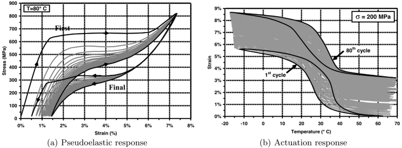
The transformation of interest to SMAs also produces additional complexity to the response. For instance, during initial cycles, cyclic instabilities are typically observed resulting in the generation of irrecoverable plastic strains and permanent changes in the transformation hysteresis. These deforma-tions arise from plastic accommodation being necessary in addition to transformation behaviors to satisfy compatibility constraints [226] although such strains saturate via repeated cycling. Often, this
6 0" 100" 200" 300" 400" 500" 600" 700" *150" *100" *50" 0" 50" 100" 150" 200" 250" St re ss "(MP a) " Temperature"(°C)" Af As Ms Mf (A) (B) M artensite Austenite CA CM
(a) Uniaxial stress-temperature phase diagram with transformation surfaces and loading paths for the ac-tuation and pseudoelastic cases presented
0" 0.5" 1" 1.5" 2" 2.5" 3" 3.5" 4" 4.5" 5" )50" 0" 50" 100" 150" St ra in "(%) " Temperature"(°C)" 0" 100" 200" 300" 400" 500" 600" 700" 0" 1" 2" 3" 4" 5" 6" 7" St re ss "(MP a) " Strain"(%)" (A) (B) EM EA H "act
(b) (Top) Actuation (isobaric cooling heating cycles) response under a constant 100 MPa load and (bottom) the pseudoelastic response
Fig. 3: Characteristics SMA behaviors: (a) phase diagram and (b) the corresponding responses. Pre-sented results correspond to a NiTi (50.8 at% Ni) material with properties given in Table 3 of Lagoudas et al.[233].
process is referred to as transformation induced plasticity (TRIP) and the corresponding strains are referred to as TRIP strains. Examples of this behavior with respect to both the pseudoelastic and actuation responses are presented in Fig. 4 in which clear variations in the response is noted over repeated cycling. First, a clear permanent deformation is developed in both cases which continues to grow with cycle. Furthermore, a clear change in transformation temperatures (or stresses in the pseudoelastic case) during cycling is evident. Additionally, and more clearly presented in the pseudoe-lastic case (Fig. 4a), the recoverable strain and hysteresis also reduce with further cycling but with a decreasing rate. TRIP strains induced by cycling also result in the generation of back (residual) stresses that give rise to a two-way SME (TWSME) in which a macroscopic actuation strain may be produced even under no external biasing loads. Such cases are primarily concerned with complete transformation cycles although a number of investigations have also studied the evolution of partial, internal transformation loops [412, 152, 61]. Finally, depending on the geometry, convective boundary conditions and associated heat transfer, the latent heat of transformation may have a strong impact on the deformation response and the stress–strain hysteresis loop area of SMAs as shown experimentally in [364] and is also responsible for apparent rate dependencies [400]. As such, the thermal response of SMAs in different configurations has been extensively investigated [288,298,463].
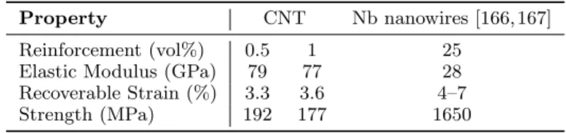
In order to enable subsequent discussion and comparison with composite materials, some represen-tative mechanical properties of different SMA alloys are given in Table 1.
Table 1: Properties of Selected Bulk SMAs (Data from Table 2.5 of [232]).
Property NiTi NiTiCu NiTiPd CuAlNi
EA(GPa) 70 50 15 90
EM (GPa) 30 25 25 80
H (%) 6 5 3 4